Introduction
The document describes a quick reference on how to configure and verify VXLAN Xconnect on Nexus 9000 Switches.
Prerequisites
Requirements
Cisco recommends that you have knowledge of VXLAN EVPN.
Components Used
The information in this document is based on these software and hardware versions:
- N9K-C93180YC-EX
- NXOS 9.2(1)
The information in this document was created from the devices in a specific lab environment. All of the devices used in this document started with a cleared (default) configuration. If your network is live, make sure that you understand the potential impact of any command.
Overview
VXLAN Xconnect is a mechanism for a point-to-point tunnel for data and control packets from one Leaf to another. Inner Dot1q Tags are preserved and VXLAN encapsulated within the outer VNID which is specified as the Xconnect VNID. Layer 2 Control Frames such as Link Layer Discovery Protocol (LLDP), Cisco Discovery Protocol (CDP), Spanning Tree Protocol (STP) are VXLAN Encapsulated and sent over to other ends of the Tunnel.
Topology

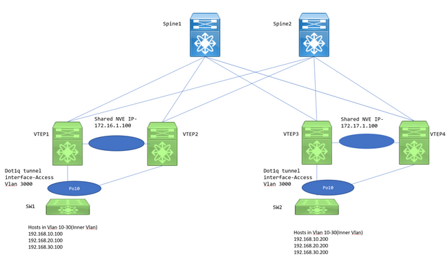
VTEP1, VTEP2, VTEP3, and VTEP4 are two vPC VTEP pairs configured in such a way that the inner dot1q tags from downstream switches are preserved and when VXLAN encapsulated, use outer VLAN ID's VXLAN VNID in order to send over to the remote VTEP. All VTEPs are N9K-C93180YC-EX.
Downstream switches are Nexus 3ks which are configured with Switch Virtual Interface (SVIs) in respective VLANs to mimic the hosts.
Configure
1. Outer VLAN used in this Xconnect topology is 3000. This would be the one with the VNID and Xconnect configuration.
VTEP1# sh run vlan 3000

vlan 3000
  vn-segment 1003000
  xconnect
2. Feature NGOAM has to be enabled and needs this configuration.
VTEP1# sh run ngoam

feature ngoam

ngoam install acl
ngoam xconnect hb-interval 5000
3. Dot1q tunnel configuration towards the downstream switch.
VTEP1# sh run int po10

interface port-channel10
  switchport
  switchport mode dot1q-tunnel
  switchport access vlan 3000
  speed 40000
  no negotiate auto
  vpc 10
The vPC configurations are required only when VTEPs are deployed as vPC. Otherwise, skip the vPC configurations mentioned in this document. VXLAN Xconnect also is configurable on a standalone VTEP.
4. Multicast group has to be defined under the NVE interface to take care of the forwarding. Note to enable ip pim sparse-mode on relevant uplinks and define PIM RP as well so that multicast routing and PIM messages are exchanged appropriately. Typically PIM RP is defined at the Spine Layer.
VTEP1# sh run int nve1

  no shutdown
  host-reachability protocol bgp
  source-interface loopback1
  member vni 1003000 mcast-group 239.30.30.30
5. Infra VLAN needs to be specified and allowed as the native VLAN within the peer link. This step is needed for vPC VTEPs.
VTEP1# sh run span|infra
no spanning-tree vlan 3000
system nve infra-vlans 999

VTEP1# sh run int po1

interface port-channel1
  switchport
  switchport mode trunk
  switchport trunk native vlan 999
  spanning-tree port type network
  vpc peer-link
6. BGP/EVPN Configuration: L2VPN EVPN neighborships are needed between leaf/spine to exchange the Type 3 routes that are required to establish the VXLAN Xconnect.
- Here, the IP addresses- 192.168.100.1 and 192.168.100.2 are the Spines in the topology. Typically the L2VPN EVPN neighborships are formed to the Spines. Spines configure all Leaf switches as Route reflector clients in an iBGP Scenario.
- It is recommended to use separate Loopbacks for BGP/OSPF and NVE purposes.
feature bgp

router bgp 65000
  router-id 192.168.100.3
  neighbor 192.168.100.1
    remote-as 65000
    update-source loopback0
    address-family l2vpn evpn
      send-community
      send-community extended
  neighbor 192.168.100.2
    remote-as 65000
    update-source loopback0
    address-family l2vpn evpn
      send-community
      send-community extended

evpn
  vni 1003000 l2
    rd auto
    route-target import auto
    route-target export auto
Note: STP has to be disabled within the Xconnect VLAN. MAC learning will not be happening within Xconnect VLAN which essentially means there is no Type 2 bgp l2vpn evpn updates for MAC addresses Due to this, traffic from one vtep will be encapsulated with the outer destination IP Address set to the Mcast-group(239.30.30.30) defined for the Xconnect VLAN.
Verify
Use this section to confirm that your configuration works properly.
1. BGP neighborship.
 VTEP1# sh bgp l2vpn evpn sum
BGP summary information for VRF default, address family L2VPN EVPN
BGP router identifier 192.168.100.3, local AS number 65000
BGP table version is 14, L2VPN EVPN config peers 2, capable peers 1
4 network entries and 5 paths using 756 bytes of memory
BGP attribute entries [3/492], BGP AS path entries [0/0]
BGP community entries [0/0], BGP clusterlist entries [2/8]

Neighbor        V    AS MsgRcvd MsgSent   TblVer  InQ OutQ Up/Down  State/PfxRcd
192.168.100.1   4 65000      92      90       14    0    0 01:21:41 2
2. Receive Type 3 prefixes.
VTEP1# sh bgp l2vpn evpn
BGP routing table information for VRF default, address family L2VPN EVPN
BGP table version is 14, Local Router ID is 192.168.100.3
Status: s-suppressed, x-deleted, S-stale, d-dampened, h-history, *-valid, >-best
Path type: i-internal, e-external, c-confed, l-local, a-aggregate, r-redist, I-injected
Origin codes: i - IGP, e - EGP, ? - incomplete, | - multipath, & - backup

   Network            Next Hop            Metric     LocPrf     Weight Path
Route Distinguisher: 192.168.100.3:35767    (L2VNI 1003000)
*>l[3]:[0]:[32]:[172.16.1.100]/88
                      172.16.1.100                      100      32768 i
* i[3]:[0]:[32]:[172.17.1.100]/88											<<< bgp type 3
                      172.17.1.100                      100          0 i
*>i                   172.17.1.100                      100          0 i

Route Distinguisher: 192.168.100.5:35767
*>i[3]:[0]:[32]:[172.17.1.100]/88
                      172.17.1.100                      100          0 i

Route Distinguisher: 192.168.100.6:35767
*>i[3]:[0]:[32]:[172.17.1.100]/88
                      172.17.1.100                      100          0 i
3. NVE Peering.
 VTEP1# sh nve peer
Interface Peer-IP          State LearnType Uptime   Router-Mac
--------- ---------------  ----- --------- -------- -----------------
nve1      172.17.1.100     Up    CP        00:58:06 n/a


VTEP1# show nve vni
Codes: CP - Control Plane        DP - Data Plane
       UC - Unconfigured         SA - Suppress ARP
       SU - Suppress Unknown Unicast

Interface VNI      Multicast-group   State Mode Type [BD/VRF]      Flags
--------- -------- ----------------- ----- ---- ------------------ -----
nve1      1003000  239.30.30.30      Up    CP   L2 [3000]                  Xconn  <<<
4. NGOAM checks.
VTEP1# show ngoam xconnect sess all

States: LD = Local interface down, RD = Remote interface Down
          HB = Heartbeat lost, DB = Database/Routes not present
          * - Showing Vpc-peer interface info
Vlan          Peer-ip/vni      XC-State       Local-if/State    Rmt-if/State
===============================================================================
3000  172.17.1.100 / 1003000      Active          Po10 / UP          Po10 / UP


VTEP1# show ngoam xconnect sess 3000
Vlan ID: 3000
Peer IP: 172.17.1.100  VNI : 1003000
State: Active                                       <<< State should be active
Last state update: 12/10/2018 17:13:45.337
Local interface: Po10  State:  UP
Local vpc interface Po10  State:  UP
Remote interface: Po10  State:  UP
Remote vpc interface: Po10  State:  UP
Once the NGOAM session is up, the N3k's would see each other in CDP. STP BPDUs are also tunnelled so the switches agree upon the root bridge placement too.
5. Verifications at the downstream switches.
SW1(config)# sh span vl 10

VLAN0010
  Spanning tree enabled protocol rstp
  Root ID    Priority    32778
             Address     7079.b348.6cb7
             This bridge is the root
             Hello Time  2  sec  Max Age 20 sec  Forward Delay 15 sec

  Bridge ID  Priority    32778  (priority 32768 sys-id-ext 10)
             Address     7079.b348.6cb7
             Hello Time  2  sec  Max Age 20 sec  Forward Delay 15 sec

Interface        Role Sts Cost      Prio.Nbr Type
---------------- ---- --- --------- -------- --------------------------------
Po10             Desg FWD 1         128.4105 P2p

SW2(config)# sh span vl 10

VLAN0010
  Spanning tree enabled protocol rstp
  Root ID    Priority    32778
             Address     7079.b348.6cb7
             Cost        1
             Port        4105 (port-channel10)
             Hello Time  2  sec  Max Age 20 sec  Forward Delay 15 sec

  Bridge ID  Priority    32778  (priority 32768 sys-id-ext 10)
             Address     707d.b964.9441
             Hello Time  2  sec  Max Age 20 sec  Forward Delay 15 sec

Interface        Role Sts Cost      Prio.Nbr Type
---------------- ---- --- --------- -------- --------------------------------
Po10             Root FWD 1         128.4105 P2p
SW1(config)# show ip int b
IP Interface Status for VRF "default"(1)
Interface            IP Address      Interface Status
Vlan10               192.168.10.100  protocol-up/link-up/admin-up
Vlan20               192.168.20.100  protocol-up/link-up/admin-up
Vlan30               192.168.30.100  protocol-up/link-up/admin-up

SW2(config)# show ip int b
IP Interface Status for VRF "default"(1)
Interface            IP Address      Interface Status
Vlan10               192.168.10.200  protocol-up/link-up/admin-up
Vlan20               192.168.20.200  protocol-up/link-up/admin-up
Vlan30               192.168.30.200  protocol-up/link-up/admin-up

SW1(config)# ping 192.168.10.200
PING 192.168.10.200 (192.168.10.200): 56 data bytes
64 bytes from 192.168.10.200: icmp_seq=0 ttl=254 time=0.826 ms
64 bytes from 192.168.10.200: icmp_seq=1 ttl=254 time=0.531 ms
64 bytes from 192.168.10.200: icmp_seq=2 ttl=254 time=0.54 ms
64 bytes from 192.168.10.200: icmp_seq=3 ttl=254 time=0.522 ms
64 bytes from 192.168.10.200: icmp_seq=4 ttl=254 time=0.571 ms
Troubleshoot
There is currently no specific troubleshooting information available for this configuration.
Caveats
1. The dot1q tunnel interfaces will be stuck in error disabled state in an Xconnect VXLAN setup if the configurations within vPC switches are not consistent. Below are some of the cases wherein the interface will be in error disabled;
- If the VLAN to VN-segment is not defined on both the vPC switches.
- If the NVE to multicast group is not defined on both the vPC switches.
- If the NGOAM Heartbeats are not received (use ethanalyzer with filter=cfm to catch the NGOAM heartbeat packets).
- Even if the dot1q tunnel interface is orphan connected in a vPC setup, it is still required to configure the multicast group under the NVE Interface for the VN-segment which is part of Xconnect on both the switches.
- NGOAM heartbeats are processed/sent by the vPC Primary switch. Heartbeat messages that land on vPC secondary will be synced to the primary
2. When Xconnect is configured in a VLAN, the traffic from one site to another is encapsulated with the outer destination address=multicast address defined under the NVE interface for that particular vn segment. It is recommended to use a unique multicast group for the Xconnect VLANs. Multicast in the core/Spine must be functional.
3. Multicast traffic might hit both the vPC boxes on the remote side of Xconnect; However, the Decap winner (the box which can decapsulate the BUM) will be only one switch in a vPC pair. This can be verified using the command- show forwarding multicast route group <Group address> source <SRC IP>. If the Flag shown here is a lower case v, it means the box is decap loser and if it's an Upper case V, the box is the decap winner and so can decapsulate the multicast traffic and forward it further down.
4. On 93180YC based platforms, when the Host is orphan connected to 9k1 and if there is no OIL for S, G on 9k1, a copy of the multicast packet is sent to the vPC Peer using a special encapsulation of Source IP-> 127.0.0.1 and Destination IP-> shared NVE IP and if the 9k2 has OIL for S, G entry, then the traffic forwarding will be taken care by the 9k2 to the remote sites.
Packet Capture
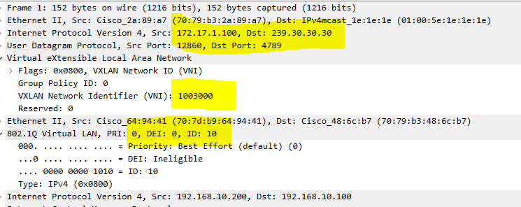
Here is a screenshot of a packet capture that was taken at the spine switch:

- Inner dot1q header=10 is preserved
- VNI used is 1003000 (which is the outer VLAN's VNID)
- The destination IP address would be the multicast group that is defined under the nve interface


 Feedback