Asymmetric Routing with Bridge Groups on Catalyst 2948G-L3 and 4908G-L3 Switches
Available Languages
Contents
Introduction
This document provides a brief discussion of the distributed bridging tables on the Catalyst 2948G-L3 and 4908G-L3 Layer 3 switches, and discusses the implications of distributed bridge tables and asymmetric routing topology when bridge groups are configured on the switch.
Prerequisites
Requirements
There are no specific requirements for this document.
Components Used
The example configurations in this document were created in a lab environment with these devices (with the configurations cleared):
-
Catalyst 2948G-L3 that runs Cisco IOS 12.0(7)W5(15d)
-
Two routers (no specific model or IOS)
-
A PC or other workstation that functions as a server
The configurations in this document were implemented in an isolated lab environment. Ensure that you understand the potential impact of any configuration or command on your network before you use it. The configurations on all devices were cleared with the write erase command and reloaded to ensure that they have a default configuration.
Conventions
Refer to Cisco Technical Tips Conventions for more information on document conventions.
Overview of Distributed Bridge Tables
There are two typical bridging configurations on the Catalyst 2948G-L3 switch:
-
All ports belong to a single bridge group; there is no Layer 3 configuration.
-
Groups of ports belong to one or more bridge groups; Bridge Virtual Interfaces (BVIs) are used to route traffic for the various bridge groups.
In both configurations, Layer 2 forwarding table entries for a given MAC address in a bridge group are viewed with the show bridge bridge-group-number command.
Bridge table entries on the Catalyst 2948G-L3 and 4908G-L3 switches are actually formed internally of at least two entries, one on the source interface (where the device with that MAC resides) and one on each destination interface (the interface where, based on the destination MAC in the frame, the traffic sourced from that MAC is destined). This is because the learning process for populating the bridging tables on the Catalyst 2948G-L3 and 4908G-L3 switches is actually distributed on a per-port basis rather than on a switch-wide basis.
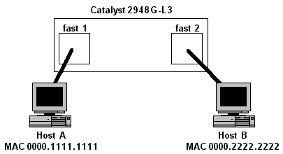
For example, consider the topology in Figure 1.
Figure 1: Catalyst 2948G-L3 Switch with Two Attached Hosts

In this topology, assume that interfaces fast 1 and fast 2 belong to the same bridge group. Two bridge table entries are added in the switch for each MAC address: one on interface fast 1 and one on interface fast 2, as shown here:
2948G-L3#show bridge 1

Total of 300 station blocks, 298 free
Codes: P - permanent, S - self

Bridge Group 1:

    Address       Action   Interface
0000.1111.1111   forward   FastEthernet1
0000.2222.2222   forward   FastEthernet2

2948G-L3#
This example shows that the Catalyst 2948G-L3 switch learned MAC address 0000.1111.1111 on interface fast 1 and MAC address 0000.2222.2222 was learned on interface fast 2.
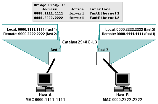
Internally, there are two entries for each MAC address: one on interface fast 1 and one on interface fast 2. For MAC address 0000.1111.1111, the entry on interface fast 1 is a "local" entry, which means that the device with MAC 0000.1111.1111 is connected to this interface, either directly or through other Layer 2 devices.
The entry for 0000.1111.1111 on interface fast 2 is a "remote" entry, which means that that the device with this MAC address is not connected to this interface. A remote bridge table entry points to the interface where the device with the MAC address is actually connected (in this case, interface fast 1).
For MAC address 0000.2222.2222, the entries are reversed -- interface fast 2 has a local entry for the MAC address, and interface fast 1 has a remote entry for the MAC address that points to interface fast 2.
Figure 2 shows how the MAC addresses are stored in the global forwarding table, as well as the state of the internal, per-port bridge tables on the Catalyst 2948G-L3 switch.
Figure 2: State of the Global and Per-Port Forwarding Table Entries

You can use the show epc patricia interface <interface> mac to see the actual internal state of the bridge table entries (the patricia tree is the data structure used to store and access the bridge table). For example, here is the internal state of the bridge table ("mac") entries for interface fast 1:
2948G-L3#show epc patricia interface fast 1 mac
1# MAC addr:0000.0000.0000  VC:0 Entry:
2# MAC addr:0900.2b01.0001 MyMAC
3# MAC addr:0180.c200.0000 MyMAC
4# MAC addr:0100.0ccc.cccd MyMAC
5# MAC addr:0100.0ccc.cccc MyMAC
6# MAC addr:0001.43a0.cc07 HsrpMAC
7# MAC addr:0000.2222.2222  IF Number:5 Entry:Remote
8# MAC addr:0000.1111.1111  IF Number:4 Entry:Local
 Total number of MAC entries: 8
2948G-L3#
Notice that the "Local" entry for interface fast 1 is for MAC address 0000.1111.1111, and the "Remote" entry is for MAC address 0000.2222.2222.
The opposite is true for interface fast 2:
2948G-L3#show epc patricia interface fast 2 mac
1# MAC addr:0000.0000.0000  VC:0 Entry:
2# MAC addr:0900.2b01.0001 MyMAC
3# MAC addr:0180.c200.0000 MyMAC
4# MAC addr:0100.0ccc.cccd MyMAC
5# MAC addr:0100.0ccc.cccc MyMAC
6# MAC addr:0001.43a0.cc08 HsrpMAC
7# MAC addr:0000.2222.2222  IF Number:5 Entry:Local
8# MAC addr:0000.1111.1111  IF Number:4 Entry:Remote
 Total number of MAC entries: 8
2948G-L3#
Here, the "Local" entry for interface fast 2 is for MAC address 0000.2222.2222, and the "Remote" entry is for MAC address 0000.1111.1111.
Implications of Asymmetric Routing with Bridge Groups
In the case where a bridging configuration is used in the Catalyst 2948G-L3 or 4908G-L3 switch along with an asymmetric routing topology, there are important functional implications with regard to distributed bridge tables. Specifically, bridging with asymmetric routing is likely to cause periodic unknown unicast flooding within a bridge group.
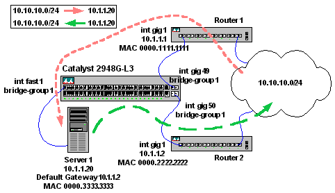
Asymmetric routing means that traffic patterns to and from a given IP subnet through the Catalyst 2948G-L3 switch do not follow the same path. For example, consider the topology in Figure 3.
Figure 3: Asymmetric Routing Topology

In this topology, traffic that originates from IP subnet 10.10.10.0/24 destined for Server 1 (10.1.1.20) enters Router 1 and is forwarded through interface gig 1 onto IP subnet 10.1.1.0/24. Interface gig 1 connects to interface gig 49 on the Catalyst 2948G-L3 switch.
Interface gig 49 belongs to bridge group 1, as does interface fast 1, where Server 1 is connected.
When Server 1 sends traffic back to the requesting host on IP subnet 10.10.10.0/24, it uses its default gateway. The default gateway of Server 1 is Router 2, connected on interface gig 50. Interface gig 50 is also a member of bridge group 1.
The important thing to notice about this topology is that, while traffic destined to Server 1 from IP subnet 10.10.10.0/24 is delivered by Router 1, the return traffic from Server 1 to IP subnet 10.10.10.0/24 passes through Router 2, not Router 1.
The result is that interface gig 49 (attached to Router 1) does not regularly see traffic sourced from Server 1 (MAC address 0000.3333.3333). The implication is that interface gig 49 eventually ages out the "Remote" bridge table entry for Server 1, which forces the Catalyst 2948G-L3 switch to flood frames it receives on interface gig 49 that are destined for Server 1 to all ports in the bridge group.
Examine why this happens in more detail. Assume that all ARP tables and bridge tables are empty.
-
Router 1 receives traffic from 10.10.10.100 destined for Server 1 (10.1.1.20).
-
Router 1 ARPs for Server 1 out interface gig 1.
-
The Catalyst 2948G-L3 switch receives the broadcast ARP on interface gig 49 and floods the frame on all ports in the bridge group -- this results in a Local entry for MAC 0000.1111.1111 on interface gig 49 and a Remote entry for MAC 0000.1111.1111 on all interfaces in the bridge group.
-
Server 1 receives the ARP request and responds to the ARP -- this results in a Local entry for MAC 0000.3333.3333 on interface fast 1 and a Remote entry for MAC 0000.3333.3333 on interface gig 49.
2948G-L3#show bridge 1

Total of 300 station blocks, 298 free
Codes: P - permanent, S - self

Bridge Group 1:

    Address       Action   Interface
0000.3333.3333   forward   FastEthernet1
0000.1111.1111   forward   Gi49

2948G-L3#show epc patricia interface gig 49 mac
1# MAC addr:0000.3333.3333  IF Number:4 Entry:Remote
2# MAC addr:0001.43a0.cd07 HsrpMAC
3# MAC addr:0000.1111.1111  IF Number:52 Entry:Local
4# MAC addr:0100.0ccc.cccd MyMAC
5# MAC addr:0180.c200.0000 MyMAC
6# MAC addr:0900.2b01.0001 MyMAC
7# MAC addr:0100.0ccc.cccc MyMAC
 Total number of MAC entries: 7
2948G-L3#show epc patricia interface fast 1 mac
1# MAC addr:0000.0000.0000  VC:0 Entry:
2# MAC addr:0900.2b01.0001 MyMAC
3# MAC addr:0180.c200.0000 MyMAC
4# MAC addr:0100.0ccc.cccd MyMAC
5# MAC addr:0100.0ccc.cccc MyMAC
6# MAC addr:0001.43a0.cc07 HsrpMAC
7# MAC addr:0000.3333.3333  IF Number:4 Entry:Local
8# MAC addr:0000.1111.1111  IF Number:52 Entry:Remote
 Total number of MAC entries: 8
2948G-L3#
In addition, Server 1 now has a complete ARP entry for Router 1 (10.1.1.1 with MAC address 0000.1111.1111).
Server1% arp -a
Net to Media Table
Device   IP Address               Mask      Flags   Phys Addr
------ -------------------- --------------- ----- ---------------
hme0   10.1.1.1             255.255.255.255       00:00:11:11:11:11
hme0   10.1.1.20            255.255.255.255 SP    00:00:33:33:33:33
hme0   224.0.0.0            240.0.0.0       SM    01:00:5e:00:00:00
Server1%
-
Router 1 completes the ARP entry for 10.1.1.20 with MAC address 0000.3333.3333.
Router1#show arp
Protocol  Address          Age (min)  Hardware Addr   Type   Interface
Internet  10.1.1.1                -   0000.1111.1111  ARPA   GigabitEthernet1
Internet  10.10.10.1              -   0050.3e7c.45a1  ARPA   GigabitEthernet8
Internet  10.1.1.20               0   0000.3333.3333  ARPA   GigabitEthernet1
Internet  10.10.10.100            1   0000.aaaa.aaaa  ARPA   GigabitEthernet8
Router1#
-
Router 1 forwards the packet from 10.10.10.100 to Server 1 (10.1.1.20) with the completed ARP entry.
-
When the Catalyst 2948G-L3 switch receives the frame, it checks the bridge table stored on interface gig 49 for the destination MAC address (0000.3333.3333) -- recall that this table is interface-specific, not global for the switch.
-
The Catalyst 2948G-L3 switch finds the Remote entry for the MAC address of Server 1 and forwards the frame to interface fast 1 ("IF Number:4" in spanning tree).
2948G-L3#show epc patricia interface gig 49 mac
1# MAC addr:0000.3333.3333  IF Number:4 Entry:Remote
2# MAC addr:0001.43a0.cd07 HsrpMAC
3# MAC addr:0000.1111.1111  IF Number:52 Entry:Local
4# MAC addr:0100.0ccc.cccd MyMAC
5# MAC addr:0180.c200.0000 MyMAC
6# MAC addr:0900.2b01.0001 MyMAC
7# MAC addr:0100.0ccc.cccc MyMAC
 Total number of MAC entries: 7
2948G-L3#
-
Server 1 receives the frame successfully.
-
When Server 1 replies, it determines (based on its IP stack configuration) that 10.10.10.100 is on a different IP subnet, so Server 1 ARPs for its default gateway IP address (10.1.1.2).
-
When the Catalyst 2948G-L3 switch receives the broadcast ARP, it floods the frame to all interfaces in the bridge group -- this results in a Local entry for MAC 0000.3333.3333 on interface fast 1 and a Remote entry for MAC 0000.3333.3333 on all interfaces in the bridge group.
-
Router 2 receives the ARP request and responds to the ARP -- this results in a Local entry for MAC 0000.2222.2222 on interface gig 50 and a Remote entry for MAC 0000.2222.2222 on interface fast 1.
2948G-L3#show bridge 1

Total of 300 station blocks, 297 free
Codes: P - permanent, S - self

Bridge Group 1:

    Address       Action   Interface
0000.2222.2222   forward   Gi50
0000.3333.3333   forward   FastEthernet1
0000.1111.1111   forward   Gi49

2948G-L3#show epc patricia interface gig 50 mac
1# MAC addr:0000.2222.2222  IF Number:53 Entry:Local
2# MAC addr:0000.3333.3333  IF Number:4 Entry:Remote
3# MAC addr:0000.1111.1111  IF Number:52 Entry:Remote
4# MAC addr:0001.43a0.cd08 HsrpMAC
5# MAC addr:0100.0ccc.cccd MyMAC
6# MAC addr:0180.c200.0000 MyMAC
7# MAC addr:0900.2b01.0001 MyMAC
8# MAC addr:0100.0ccc.cccc MyMAC
 Total number of MAC entries: 8
2948G-L3#show epc patricia interface fast 1 mac
1# MAC addr:0000.0000.0000  VC:0 Entry:
2# MAC addr:0900.2b01.0001 MyMAC
3# MAC addr:0180.c200.0000 MyMAC
4# MAC addr:0100.0ccc.cccd MyMAC
5# MAC addr:0100.0ccc.cccc MyMAC
6# MAC addr:0001.43a0.cc07 HsrpMAC
7# MAC addr:0000.2222.2222  IF Number:53 Entry:Remote
8# MAC addr:0000.3333.3333  IF Number:4 Entry:Local
9# MAC addr:0000.1111.1111  IF Number:52 Entry:Remote
 Total number of MAC entries: 9
2948G-L3#
In addition, Router 2 now has a complete ARP entry for Server 1 (10.1.1.20) with MAC address 0000.3333.3333.
Router2#show arp
Protocol  Address          Age (min)  Hardware Addr   Type   Interface
Internet  10.1.1.2                -   0000.2222.2222  ARPA   GigabitEthernet1
Internet  10.1.1.20               0   0000.3333.3333  ARPA   GigabitEthernet1
Router2#
-
Server 1 completes the ARP entry for 10.1.1.2 with MAC address 0000.2222.2222.
Server1% arp -a
Net to Media Table
Device   IP Address               Mask      Flags   Phys Addr
------ -------------------- --------------- ----- ---------------
hme0   10.1.1.1             255.255.255.255       00:00:11:11:11:11
hme0   10.1.1.2             255.255.255.255       00:00:22:22:22:22
hme0   10.1.1.20            255.255.255.255 SP    00:00:33:33:33:33
hme0   224.0.0.0            240.0.0.0       SM    01:00:5e:00:00:00
Server1%
-
Server 1 sends its response to 10.10.10.100 via its default gateway, 10.1.1.2. The frame that Server 1 transmits has MAC address 0000.2222.2222 as the destination MAC and 0000.3333.3333 as the source MAC.
-
When the Catalyst 2948G-L3 switch receives the frame, it checks the bridge table on interface fast 1 for the destination MAC address (0000.2222.2222).
-
The Catalyst 2948G-L3 switch finds the Remote entry for the MAC address of Router 2 and forwards the frame to interface gig 50 (IF Number:53 in spanning tree).
2948G-L3#show epc patricia interface fast 1 mac
1# MAC addr:0000.0000.0000  VC:0 Entry:
2# MAC addr:0900.2b01.0001 MyMAC
3# MAC addr:0180.c200.0000 MyMAC
4# MAC addr:0100.0ccc.cccd MyMAC
5# MAC addr:0100.0ccc.cccc MyMAC
6# MAC addr:0001.43a0.cc07 HsrpMAC
7# MAC addr:0000.2222.2222  IF Number:53 Entry:Remote
8# MAC addr:0000.3333.3333  IF Number:4 Entry:Local
9# MAC addr:0000.1111.1111  IF Number:52 Entry:Remote
 Total number of MAC entries: 9
2948G-L3#
At this point, everything works as expected. For example, when a network analyzer is connected on interface fast 2 (also in bridge group 1), only flood traffic (such as broadcasts and multicasts) is received by the analyzer, but a network administrator can soon be surprised when unicast traffic from 10.10.10.100 to 10.1.1.20 (Server 1) is captured by the analyzer.
The problem occurs when the Remote entry for Server 1 ages out on interface gig 49 (connected to Router 1). This occurs after 300 seconds (the bridge table aging time) if no frames with a source MAC address of 0000.3333.3333 arrive on the interface. This is how the internal bridge table appears after the Remote entry for Server 1 ages out:
2948G-L3#show epc patricia interface gig 49 mac
1# MAC addr:0001.43a0.cd07 HsrpMAC
2# MAC addr:0000.1111.1111  IF Number:52 Entry:Local
3# MAC addr:0100.0ccc.cccd MyMAC
4# MAC addr:0180.c200.0000 MyMAC
5# MAC addr:0900.2b01.0001 MyMAC
6# MAC addr:0100.0ccc.cccc MyMAC
 Total number of MAC entries: 6
2948G-L3#
The only entry is the Local entry for Router 1 -- the Remote entry for Server 1 (MAC address 0000.3333.3333) has been removed. The result is the flooding of all unicast traffic from Router 1 to Server 1 on every interface in the bridge group.
Unfortunately, the only way to isolate the problem is to check the state of the internal, per-interface bridge table entries. This is because the show bridge output indicates that the Catalyst 2948G-L3 switch still has an entry for Server 1:
2948G-L3#show bridge 1

Total of 300 station blocks, 297 free
Codes: P - permanent, S - self

Bridge Group 1:

    Address       Action   Interface
0000.2222.2222   forward   Gi50
0000.3333.3333   forward   FastEthernet1
0000.1111.1111   forward   Gi49

2948G-L3#
This is because as long as the Catalyst 2948G-L3 switch has a Local entry on any interface for a MAC address, that MAC address appears in the bridge table.
In addition, a show arp on Router 1 shows that the ARP entry is complete and correct:
Router1#show arp
Protocol  Address          Age (min)  Hardware Addr   Type   Interface
Internet  10.1.1.1                -   0000.1111.1111  ARPA   GigabitEthernet1/1
Internet  10.10.10.1              -   0050.3e7c.45a1  ARPA   FastEthernet7/1
Internet  10.1.1.20               7   0000.3333.3333  ARPA   GigabitEthernet1/1
Internet  10.10.10.100            9   0000.aaaa.aaaa  ARPA   FastEthernet7/1
Router1#
This is because the ARP aging time is 4 hours by default, significantly longer than the bridge table aging time.
There are two workarounds for this problem:
-
Redesign the routing topology so that traffic for a given remote IP subnet follows the same route into and out of the Catalyst 2948G-L3 switch.
-
Reduce the ARP aging time on router interfaces connected to the Catalyst 2948G-L3 switch to 5 minutes (with the arp timeout <seconds> interface configuration command).
The first workaround is preferred, but the second workaround can significantly reduce the amount of unicast flooding without adversely affecting performance (the increased burden of ARPing placed on the router is not significant in most cases).
With the default four hour ARP aging time, unicast flooding can occur for almost four hours. With a reduced ARP timer, unicast flooding can last four minutes at most before the bridge table entries are reinstalled. This is because, if no traffic for a host in an ARP table of a router is seen in (aging time - 60 seconds), the router re-ARPs for that host and refreshes or reinstalls the dynamic bridge table entries in the Catalyst 2948G-L3 or 4908G-L3 switch.
Note that, because there is no way to synchronize the ARP timer and the bridge table timer precisely, the second workaround most likely does not completely eliminate unicast flooding.
Related Information
Revision History
| Revision | Publish Date | Comments |
|---|---|---|
1.0 |
06-Oct-2005 |
Initial Release |
 Feedback