Configure DHCP in IOS XE EVPN/VXLAN
Available Languages
Download Options
Bias-Free Language
The documentation set for this product strives to use bias-free language. For the purposes of this documentation set, bias-free is defined as language that does not imply discrimination based on age, disability, gender, racial identity, ethnic identity, sexual orientation, socioeconomic status, and intersectionality. Exceptions may be present in the documentation due to language that is hardcoded in the user interfaces of the product software, language used based on RFP documentation, or language that is used by a referenced third-party product. Learn more about how Cisco is using Inclusive Language.
Contents
Introduction
This document describes the Dynamic Host Configuration Protocol (DHCP) configuration for Ethernet VPN (EVPN) Virtual Extensible LAN (VXLAN) in different scenarios, and specific aspects for Win2012 and Win2016 DHCP servers.
Prerequisites
Requirements
Cisco recommends that you have knowledge of EVPN/VXLAN and DHCP.
Components Used
The information in this document is based on these software and hardware versions:
- C9300
- C9400
- C9500
- C9600
- MSFT Windows Server 2012 R2
- MSFT Windows Server 2016
- Features available on Cisco IOS XE 16.9.x or later
The information in this document was created from the devices in a specific lab environment. All of the devices used in this document started with a cleared (default) configuration. If your network is live, ensure that you understand the potential impact of any command.
Configure
Network Diagram
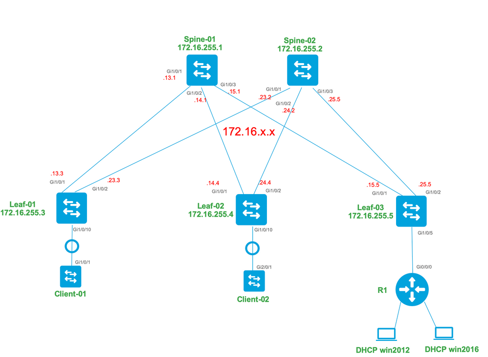
Configurations
Now, let us review the message flow between the DHCP client and server. There are 4 phases:
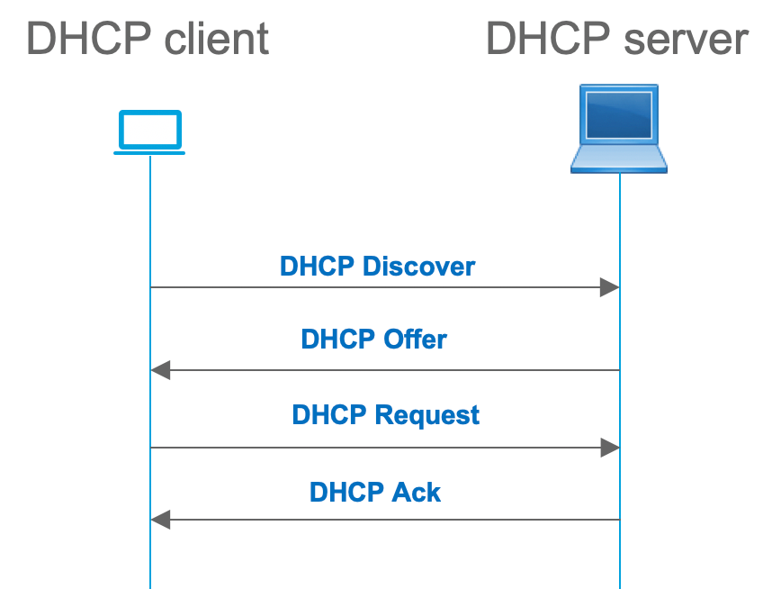
This works for cases where the client and server are in the same subnet, however, usually, this is not the case. In most cases, the DHCP server is not in the same subnet with the client and must be reachable via a layer 3 routed path versus layer 2. In this case, DHCP relay functionality is required. The DHCP relay (switch or router) feature converts broadcast to udp-encapsulated unicast which is routable and sends it to the DHCP server. It is a widely used configuration in networks these days.
Challenges with DHCP and EVPN/VXLAN Fabric:
Usually, the DHCP server is connected to EVPN fabric over the L3 network. This means that you must use the DHCP relay functionality to convert a layer 2 DHCP broadcast packet to a layer 3 unicast routable packet.
With the DHCP relay feature the DHCP call flow between the client, relay, and server works similar to this:
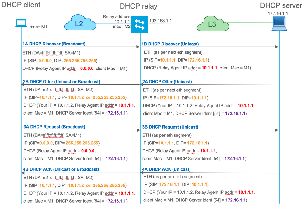
After relayed, the source IP of the packet is the Relay IP. However, this creates a problem in VXLAN/EVPN deployment as the usual source IP is non-unique due to the use of Distributed Anycast GW (DAG). Because all VTEP SVI source IPs are the same, this can cause the Reply packets from the DHCP server to be forwarded to the closest Leaf.
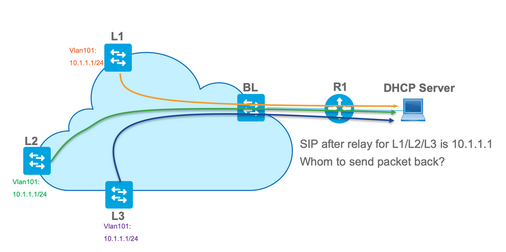
In order to solve the non-unique Source issue, you must be able to use a unique IP address for relayed DHCP packets per Leaf. Another issue is related to GIADDR replacement. On the DHCP server, you must choose the correct pool to assign the IP address. It is done from the pool, which covers the gateway IP address (giaddr). For EVPN fabric, it has to be an IP address of SVI, but after the relay, the giaddr is replaced with a relay IP address which is in this case a unique loopback.
How you can inform the DHCP server, which pools it must use?
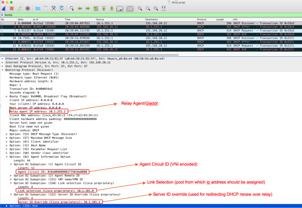
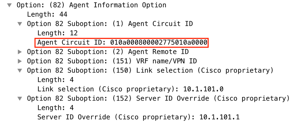
In order to solve this issue, option 82 is used. Mainly, these are the important suboptions:
- 1 - The Agent Circuit ID. In the case of VXLAN/EVPN, this suboption transfers VNI ID
- 5 - (or 150 for cisco proprietary). The Link selection suboptions which have actual subnet, from which DHCP packet came from
- 11 - (or 152 for cisco proprietary ). The Server Identifier Override suboption which has the address of the DHCP server
- 151 - The VRF name/VPN ID. This suboption has VRF name/VPN id
In a packet capture of the packet from the DHCP relay to the DHCP server, you can see these various options present in the DHCP packet as shown in the image.
Switch Configuration:
- Option 82 has all the necessary information which is needed to choose the correct DHCP pool and return the packet from the server to the correct Leaf.
- This only works if the DHCP server can process option 82 information, though not all servers fully support it (such as win2012 r2).
ip dhcp relay information option vpn        <<<  adds the VRF name/VPN ID to the option 82
ip dhcp relay information option            <<< enables option 82
!
ip dhcp snooping vlan 101-102,201-202
ip dhcp snooping
!
vlan configuration 101
 member evpn-instance 101 vni 10101
!
interface Loopback101
 vrf forwarding green
 ip address 10.1.251.1 255.255.255.255
!
interface Vlan101
 vrf forwarding green
ip dhcp relay source-interface Loopback101    <<< DHCP relay source is unique Loopback
 ip address 10.1.101.1 255.255.255.0
 ip helper-address 192.168.20.12               <<< 192.168.20.12 - DHCP server
Server Configuration
Win2012 R2 Configuration Option 1 - Unique Relay IP per VNI/SVI per VTEP
The main issue with win2012 is that option 82 is not fully supported so the "Link selection" suboption (5 or Cisco proprietary - 150) can not be used to select the right pool on the DHCP server.
To solve such an issue, this approach can be used:
- A scope for RELAY IP addresses must be created otherwise DHCP does not find a pool which matches DHCP GIADDR and ignore the packet. The full IP range must be excluded from DHCP to prevent allocation from the RELAY IP pool. We call this pool RELAY_POOL
- The scope for the IP range that you want to allocate must be created. We call this pool IP_POOL
- Superscope must be created and both scopes - RELAY_POOL and IP_POOL must be included
Let us see how the DHCP packet is processed on the server.
- DHCP packet is received by the server.
- Based on GIADDR Respective pool RELAY_POOL is chosen in the appropriate superscope.
- As there are no free IP addresses in RELAY_POOL (do you remember that full scope is excluded?), it fallback to IP_POOL in the same superscope.
- The address is allocated from the respective superpool and sent back to the Relay.
A big disadvantage of this method is that you have to have a unique loopback per VLAN/VNI per vtep as the DHCP pool is selected based on the Relay address.
This option leads us to the utilization of a big IP range for the relays IP addresses.
Option 1. Step-by-step instruction on how to configure win2012 r2.
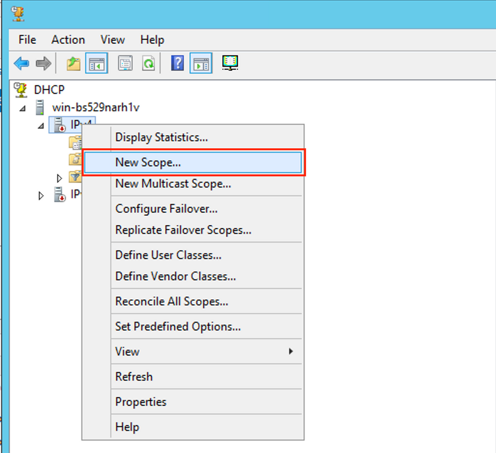
Create the DHCP scope for Relay addresses. Right-click and choose New Scope as shown in the image.
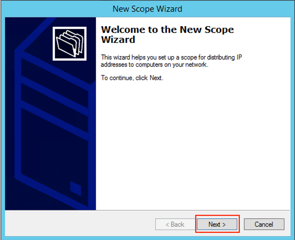
 Select Next as shown in the image.
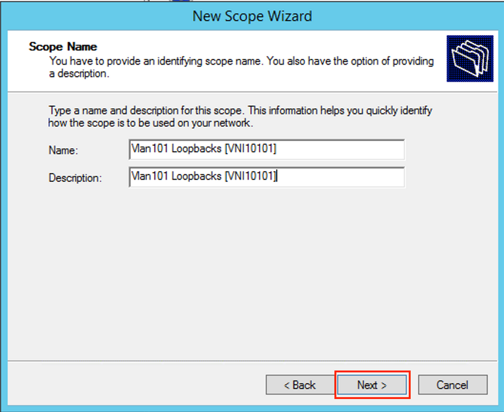
Fill in a meaningful Name, Description, and then select Next as shown in the image.
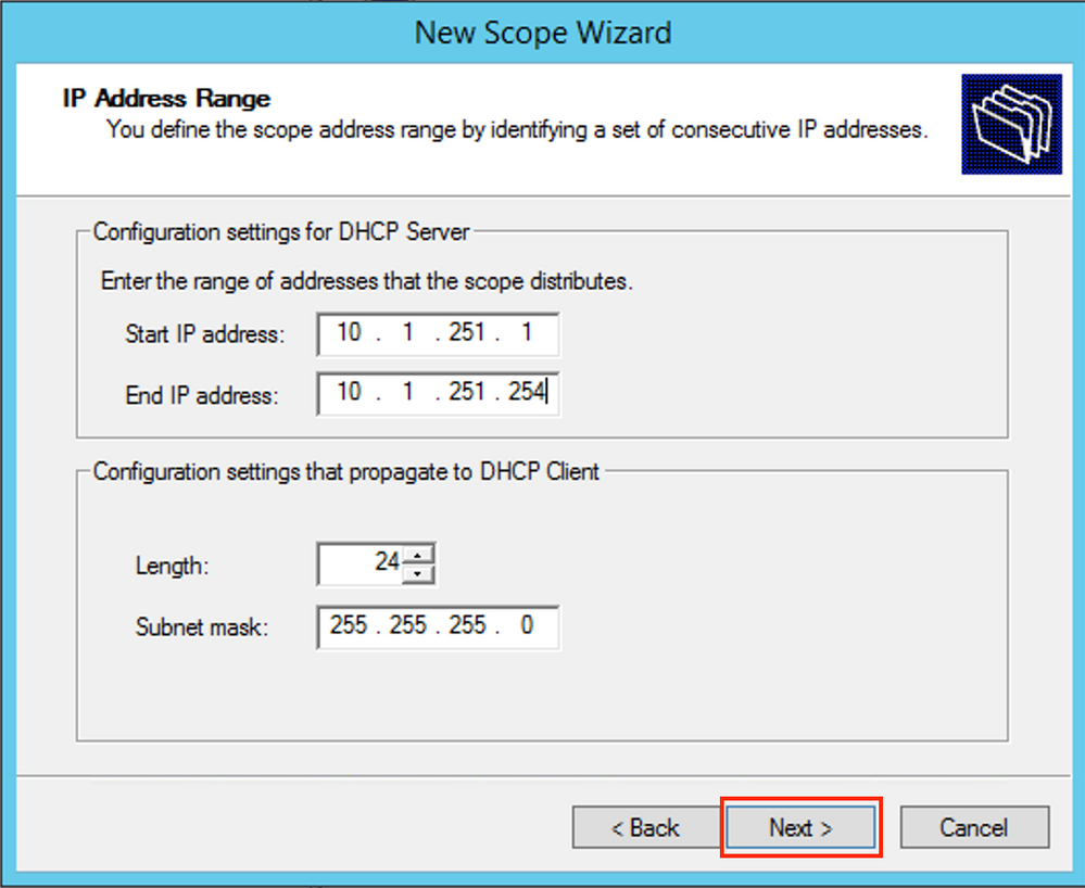
Fill in the IP address information for the Relay pool. In this example, the netmask is /24 but it can be larger or smaller (it depends on the size of the network) as shown in the image.
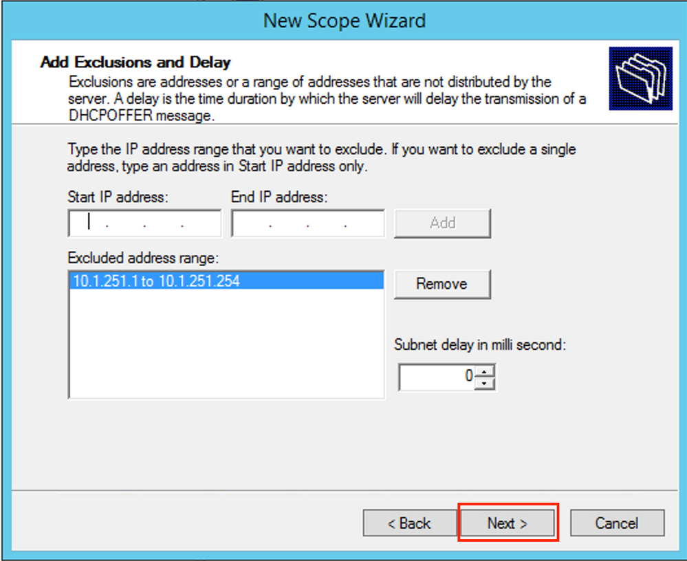
Exclude all ranges from the pool. This is important, otherwise, IP addresses can be allocated from this pool.
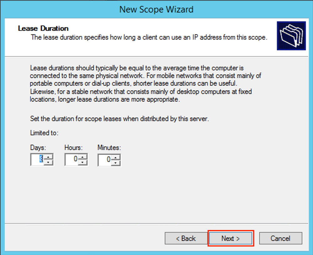
 Configure the Lease time (by default it is 8 days) as shown in the image.
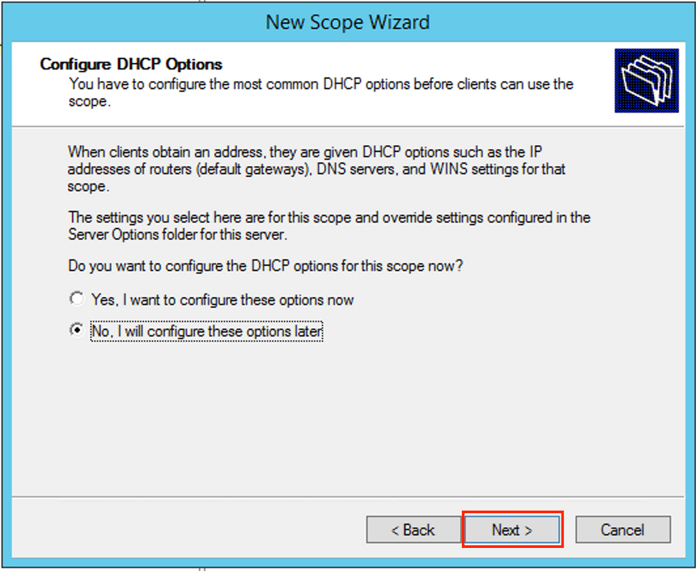
You can configure the DHCP option parameters like DNS/WINS (skipped in this example).
 Activate the scope as shown in the image.
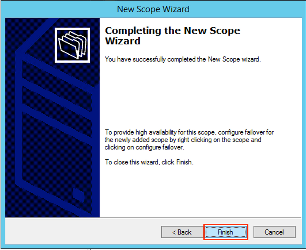
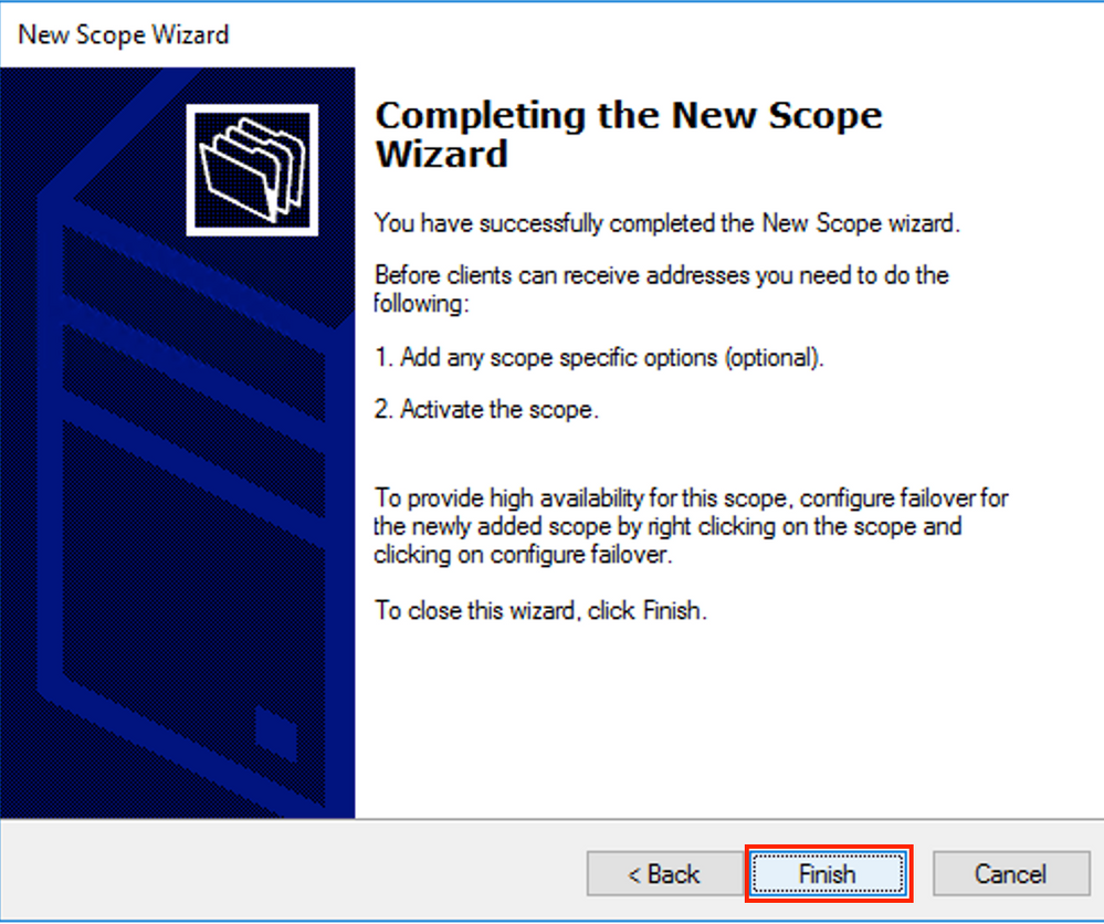
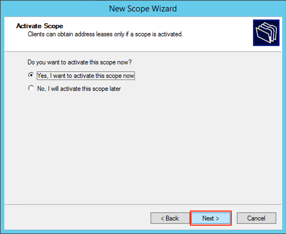 Finish the configuration as shown in the image.
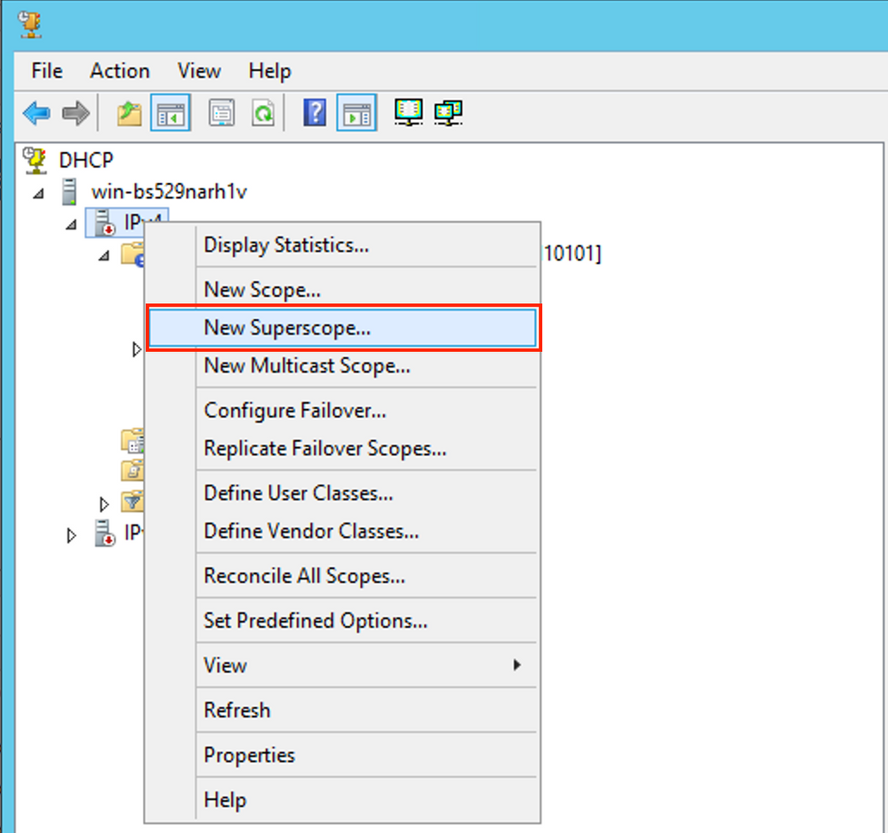
 Now create a superscope. Right-select and choose New Superscope as shown in the image.
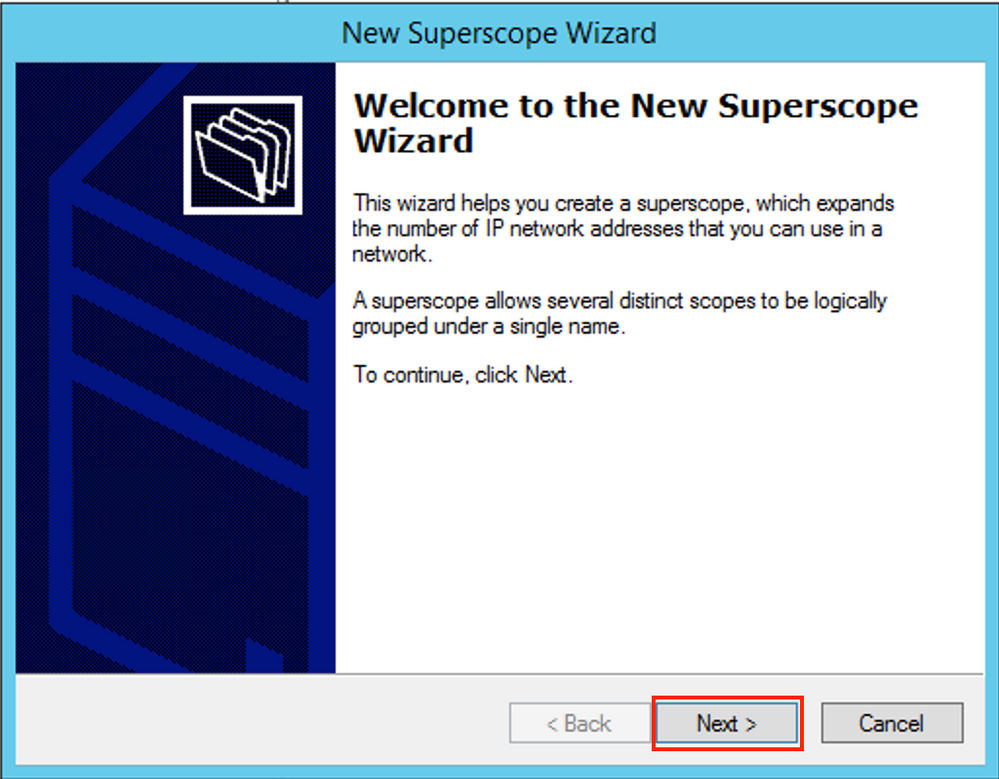
Select Next as shown in the image.
 Choose a meaningful name for the Superscope as shown in the image.
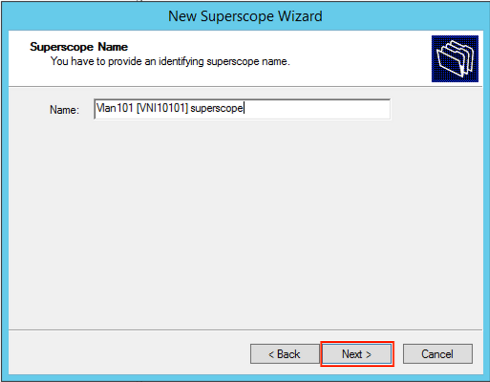 Choose the scope to be added to the superscope.
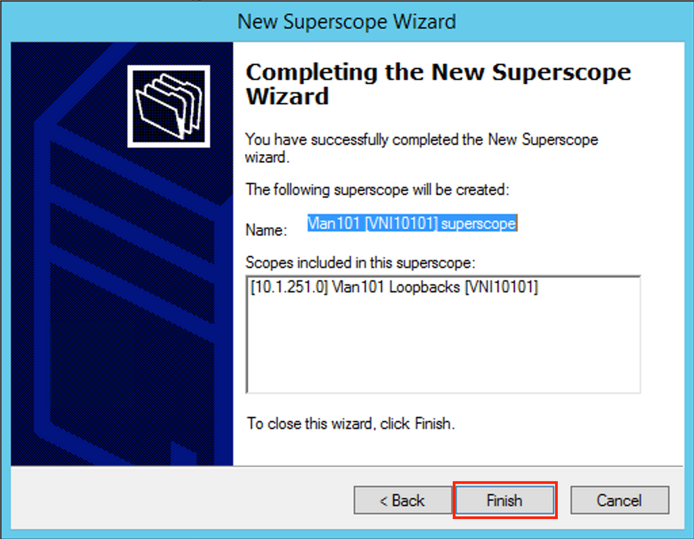
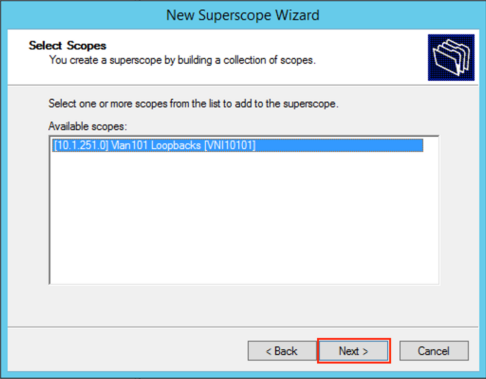 Finish the setup as shown in the image.
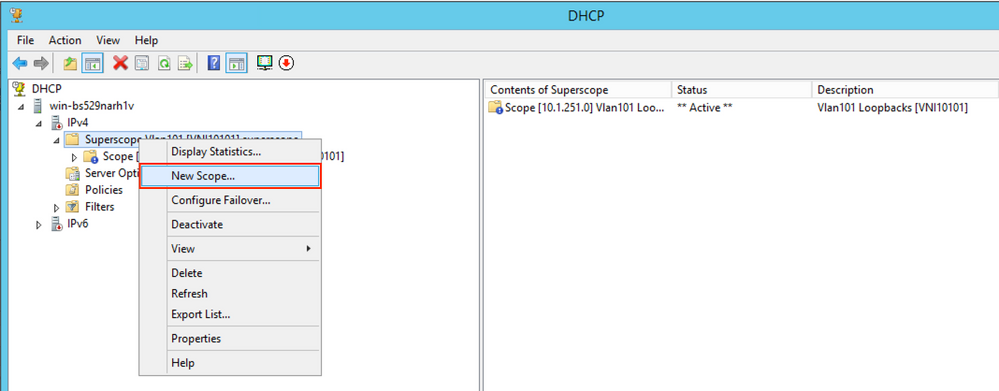
 Create a DHCP pool from which IP addresses are allocated. Right-click and select New Scope... as shown in the image.
 Select Next as shown in the image.
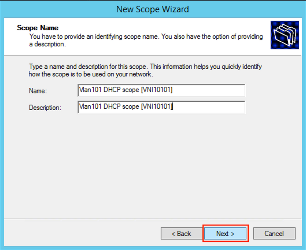
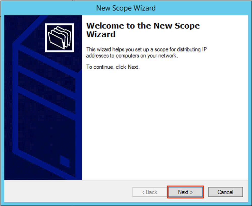 Choose a meaningful name and description as shown in the image.
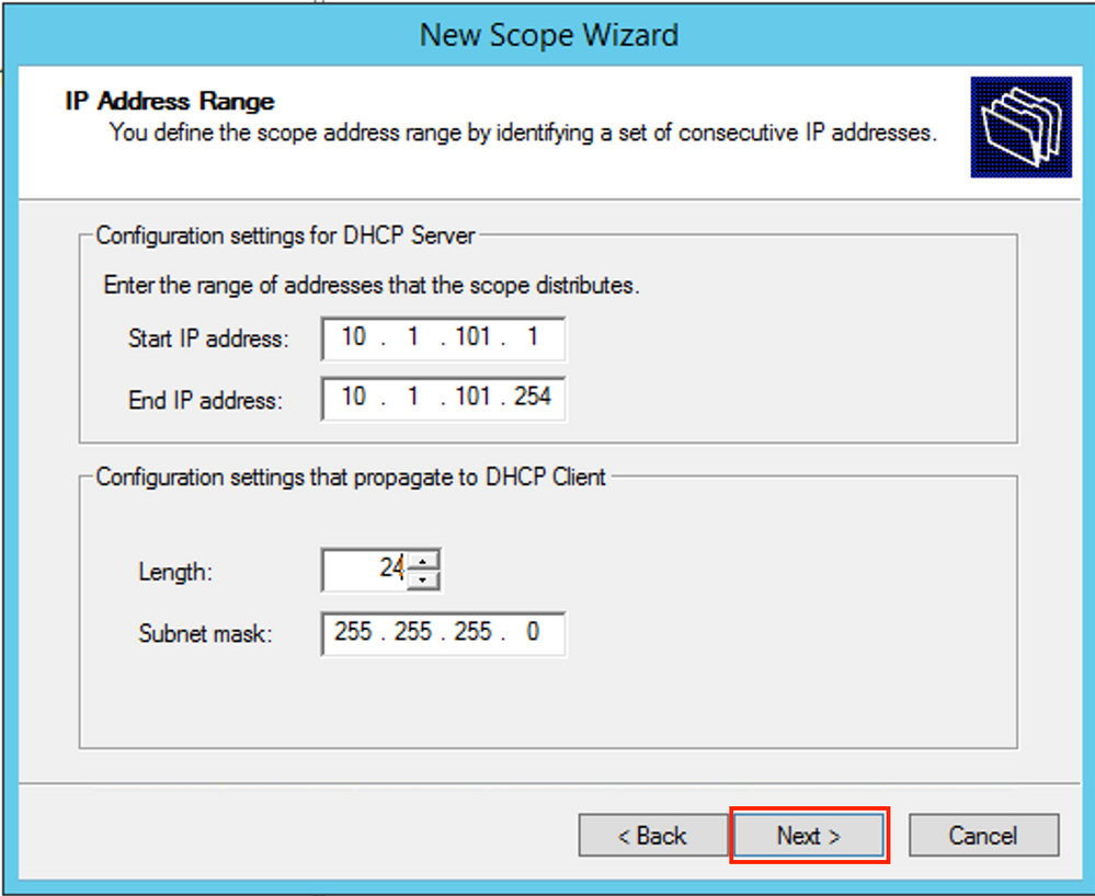
 Specify the network and mask for the pool of which you want to allocate the IP addresses to the clients as shown in the image.
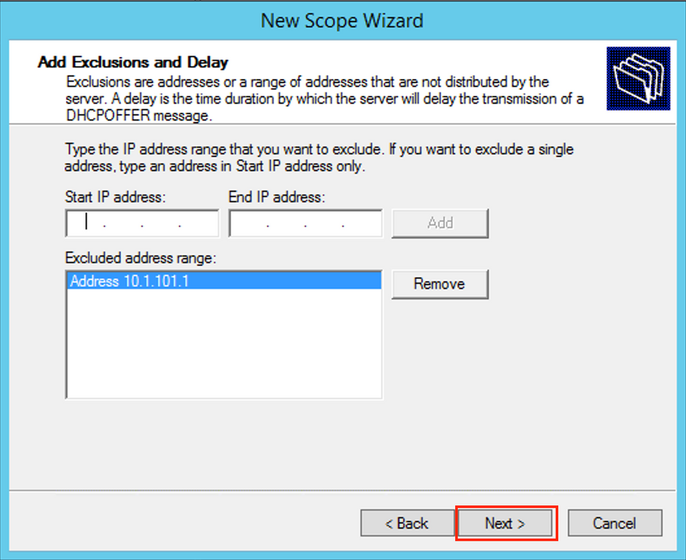
 Exclude the IP address of the DEFAULT Gateway from the pool (in this example it is 10.1.101.1) as shown in the image.
 Specify the Lease timer as shown in the image.
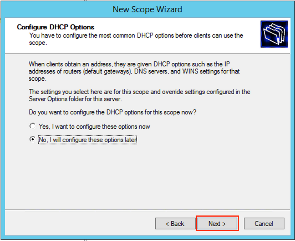
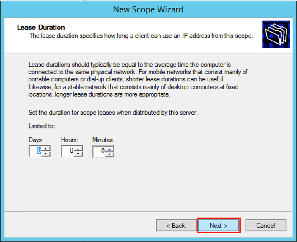 Optionally you can specify DNS/WINS (skipped in this example).
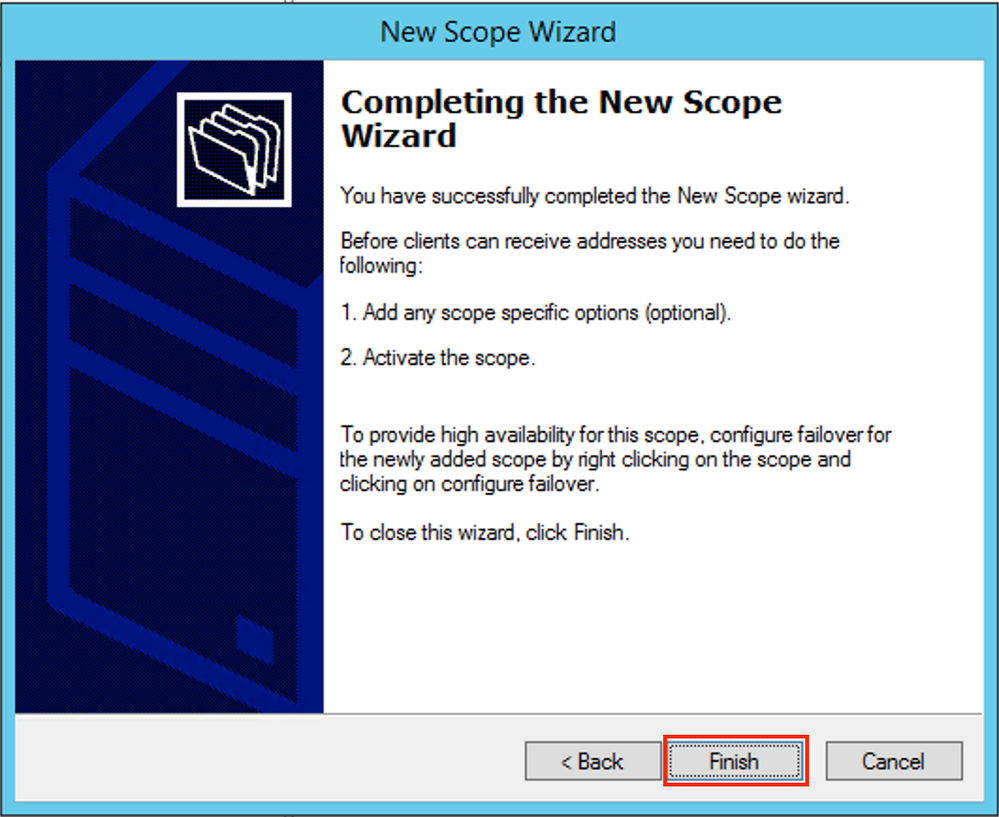
 Finish the configuration as shown in the image.
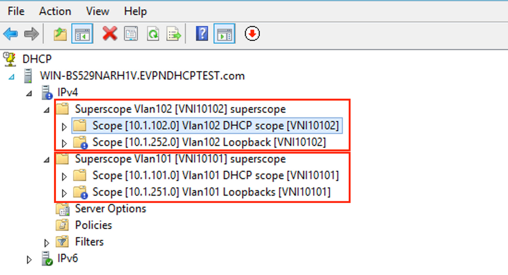
 After pool creation, a policy must be created for the pool.
- In the policy Agent Circuit ID [1] is matched
- If you have several Vlans/VNIs you have to create superpool with subpools for relay IP addresses and the actual IP range for allocation per each VLAN/VNI
- This example uses VNIs 10101 and 10102
Switch configuration:
ip dhcp relay information option vpn   <<<  add the VRF name/VPN ID to the option 82
ip dhcp relay information option       <<< enables option 82
!
ip dhcp snooping vlan 101-102,201-202
ip dhcp snooping
!
vlan configuration 101
 member evpn-instance 101 vni 10101
!
interface Loopback101
 vrf forwarding green
 ip address 10.1.251.1 255.255.255.255
!
interface Loopback102
 vrf forwarding green
 ip address 10.1.251.2 255.255.255.255
!
interface Vlan101
 vrf forwarding green
 ip dhcp relay source-interface Loopback101  <<< DHCP relay source is unique Loopback101
 ip address 10.1.101.1 255.255.255.0
ip helper-address 192.168.20.12             <<< 192.168.20.12 - DHCP server
!
interface Vlan102
 vrf forwarding green
 ip dhcp relay source-interface Loopback102  <<< DHCP relay source is unique Loopback102
 ip address 10.1.101.1 255.255.255.0
ip helper-address 192.168.20.12             <<< 192.168.20.12 - DHCP server
Win2012 R2 Configuration Option 2 - Match the Agent Circuit ID Field
- The disadvantage of the last approach is the high utilization of unique loopback, so another option is to match the Agent Circuit ID field.
- The steps are the same, but you add policy creation for scope selection not based on the Agent Circuit ID field rather than Relay IP.
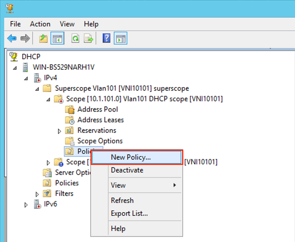
Policy creation. Right-click on pool and select New Policy as shown in the image.
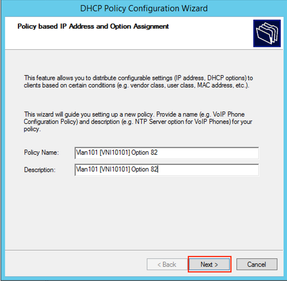
 Choose a meaningful name and description for the policy as shown in the image.
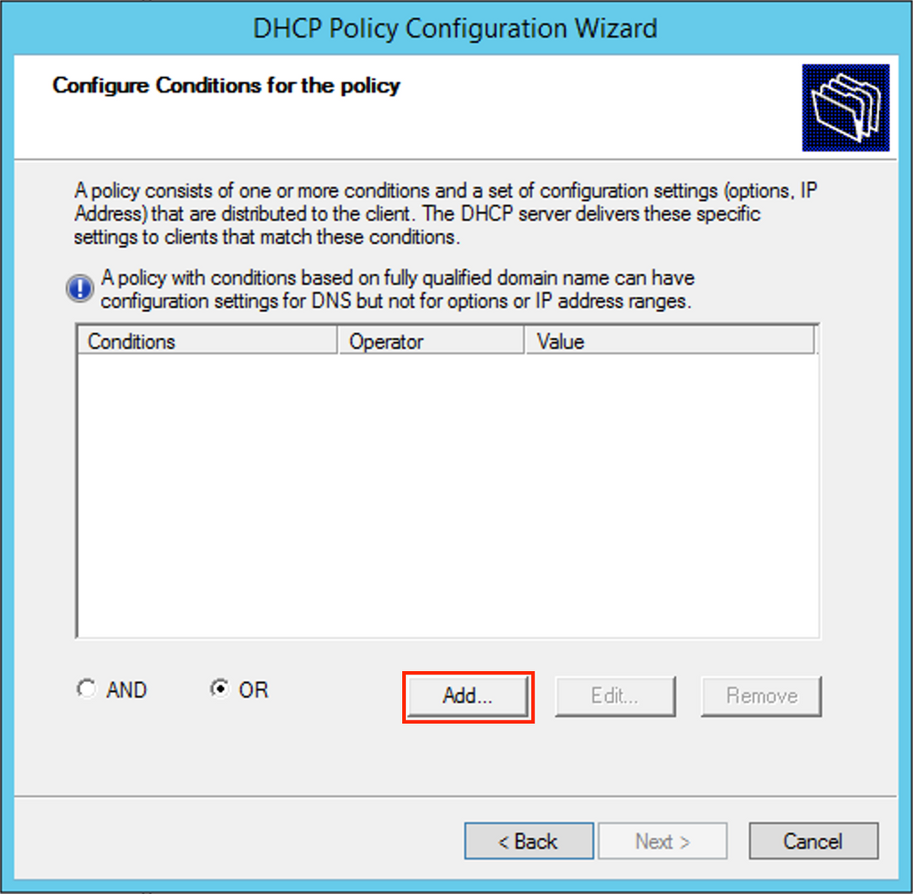
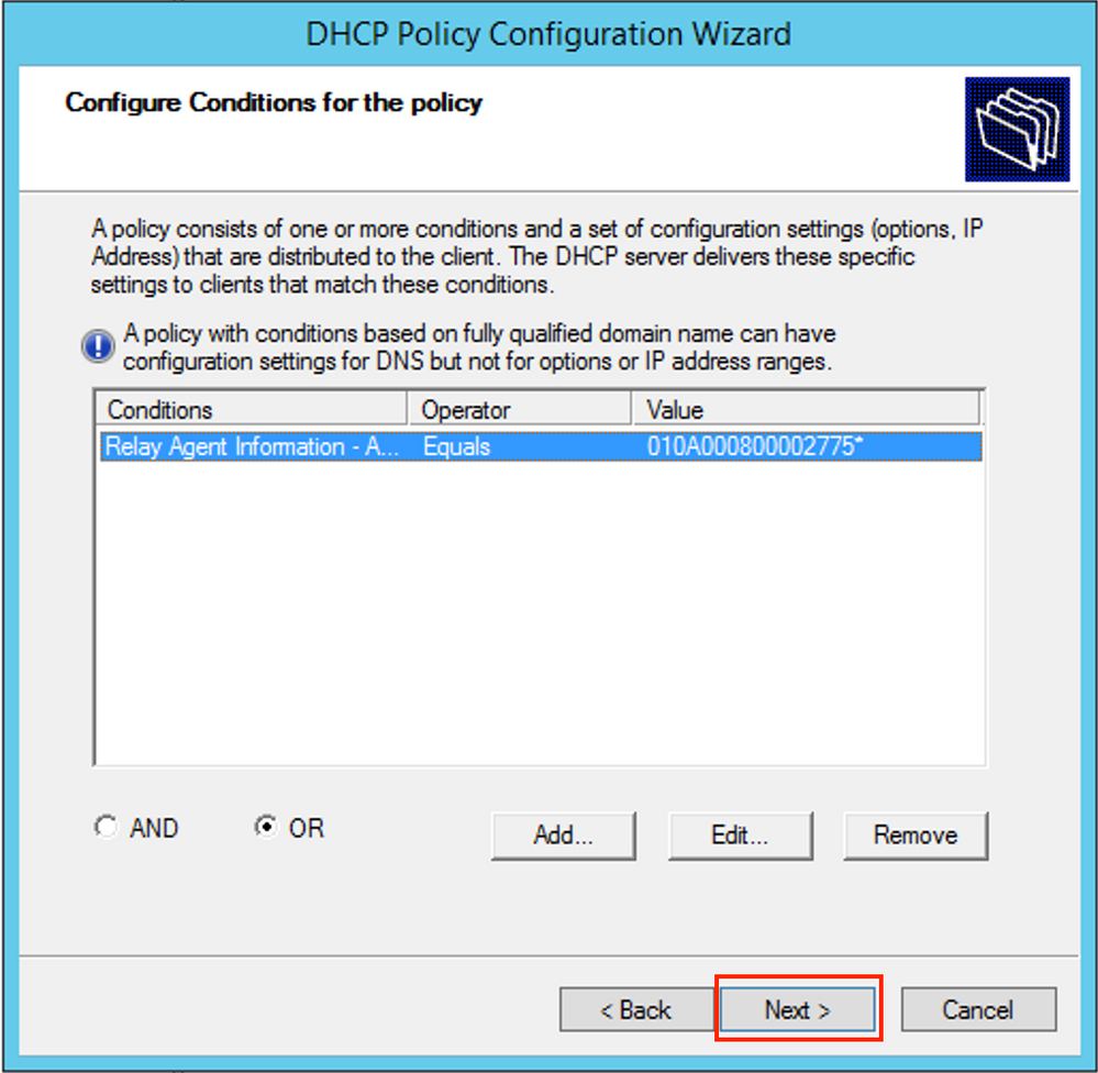
Add the new condition as shown in the image.
 Enter the proper Circuit ID (do not forget the Append Wildcard (*) box) as shown in the image.
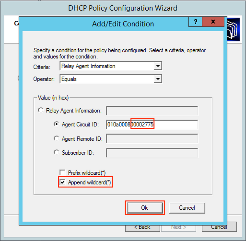 Clarification on why this number was chosen:
In Wireshark, you can see Agent Circuit ID equal to 010a000800002775010a0000, which is where this value is derived from (00002775 hex = 10101 decimal is equal to configured VNI 10101 for the VLAN 101).
Agent Circuit ID suboption is encoded in this format for VXLAN VN:
|
Suboption Type |
Length |
Circuit ID type |
Length |
VNI |
mod |
port |
|
1 byte |
1 byte |
1 byte |
1 byte |
4 bytes |
2 byte |
2 byte |
|
01 |
0a |
00 |
08 |
00002775 |
* |
* |
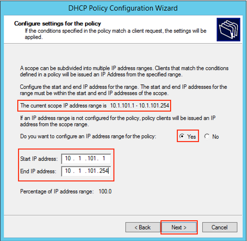
 Configure the IP range from which IP addresses are allocated. Without this configuration no allocation for current scope is possible.
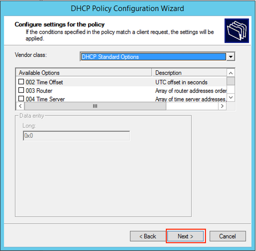
You can also select standard DHCP options at this stage as shown in the image.
 Select Finish as shown in the image.
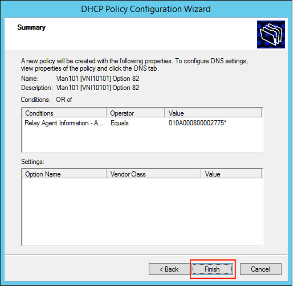
A similar configuration must be done for other ranges as shown in the image.
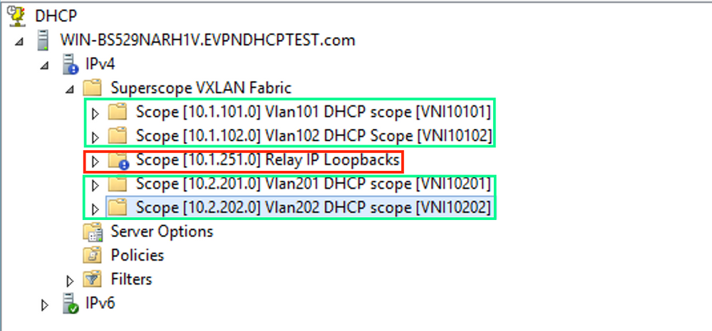
In this scenario, you can use only one unique IP address per VTEP for numbers of SVIs, not one unique loopback per VNI/SVI per VTEP.
Switch configuration:
ip dhcp relay information option vpn     <<<  adds the VRF name/VPN ID to the option 82
ip dhcp relay information option         <<< enables option 82
!
ip dhcp snooping vlan 101-102,201-202
ip dhcp snooping
!
vlan configuration 101
 member evpn-instance 101 vni 10101
!
interface Loopback101
 vrf forwarding green
 ip address 10.1.251.1 255.255.255.255
!
interface Vlan101
 vrf forwarding green
 ip dhcp relay source-interface Loopback101 <<< DHCP relay source
 ip address 10.1.101.1 255.255.255.0
 ip helper-address 192.168.20.12            <<< 192.168.20.12 - DHCP server
!
interface Vlan102
 vrf forwarding green
 ip dhcp relay source-interface Loopback101 <<< DHCP relay source
 ip address 10.1.101.1 255.255.255.0
ip helper-address 192.168.20.12            <<< 192.168.20.12 - DHCP server
Windows Server 2016 Configuration
- Windows Server 2016 supports option 82 suboptions 5 (Cisco proprietary 150) "Link selection" which means that you do not use a unique relay IP address for pool selection. Instead, the "Link selection" suboption is used which significantly simplifies the configuration.
- It would be best if you still had a pool for Relay IP addresses otherwise DHCP packet does not match any scope and is not processed.
This example demonstrates the use of the "link selection" option.
Initiate IP address pool for Relay IP addresses as shown in the image.
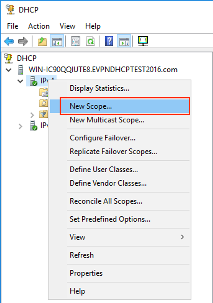
Select Next as shown in the image.
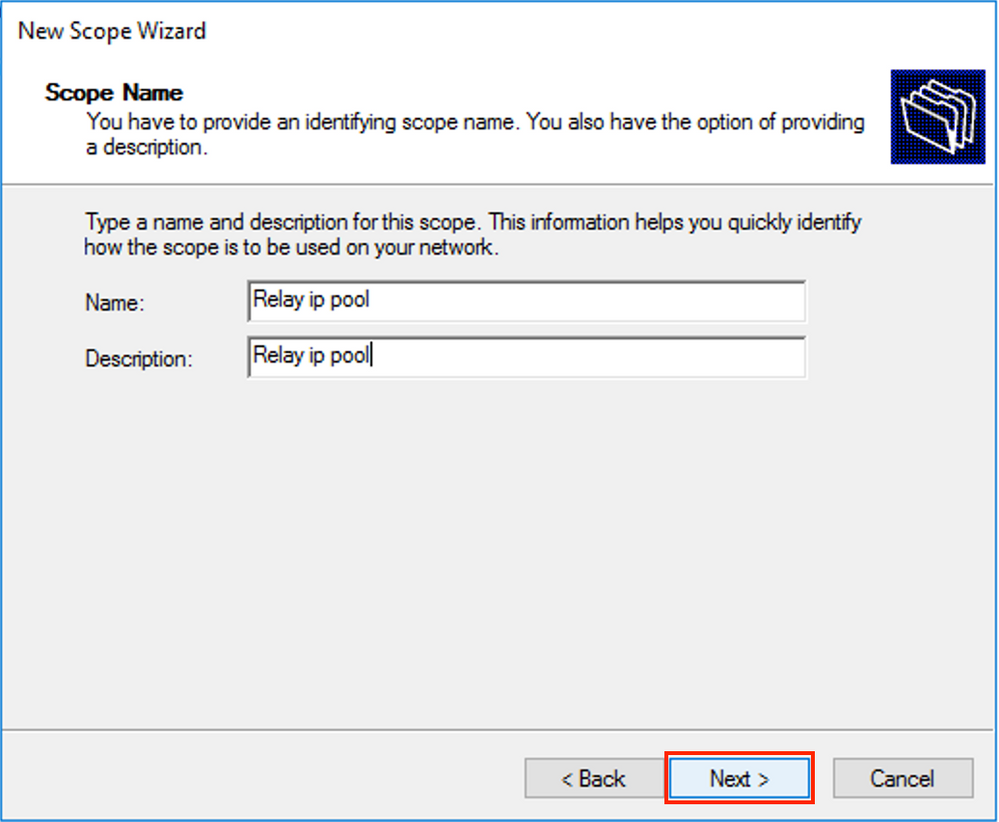
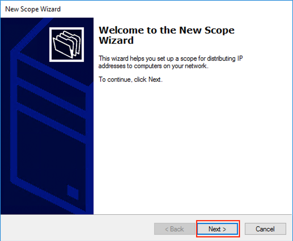 Choose a meaningful name and description for the scope as shown in the image.
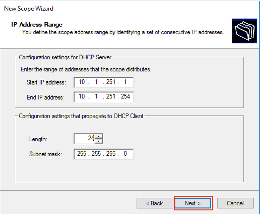
 Enter the IP address space which is used for IP relays as shown in the image.
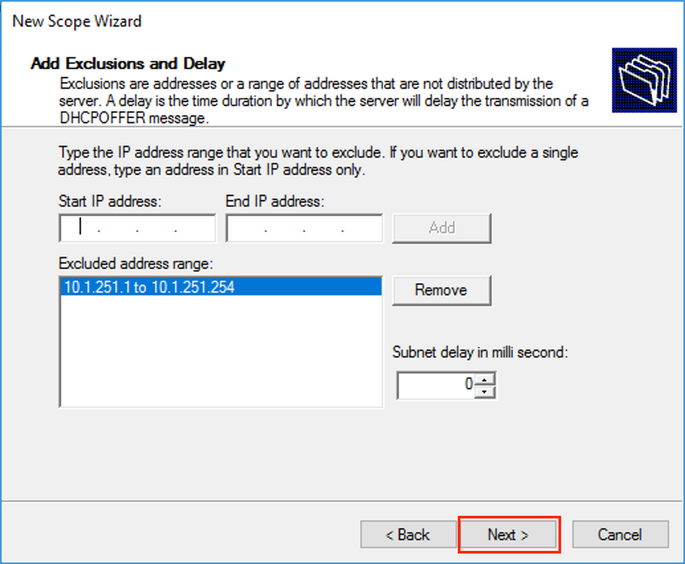
 Exclude all ranges from the scope to prevent allocation from this range as shown in the image.
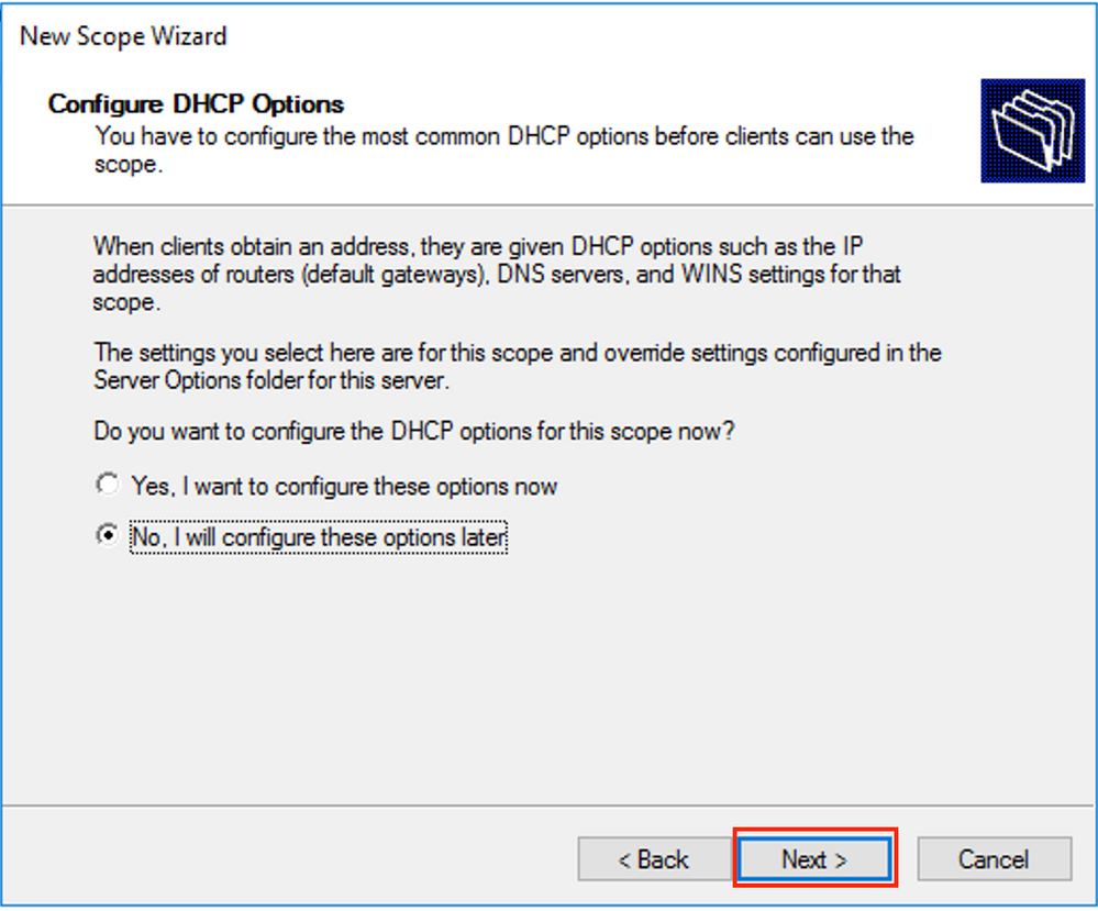
You can also choose the option DNS/WINS etc parameters (skipped in this example) as shown in the image.
 Select Finish as shown in the image.
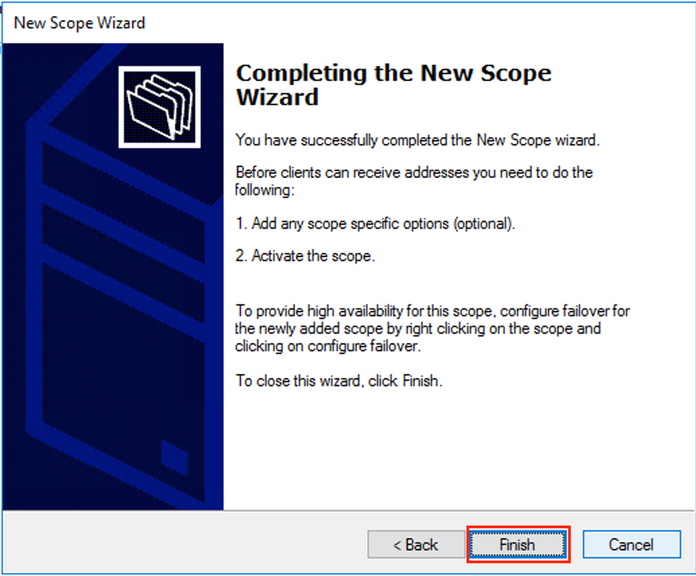
The scope for relays is now ready.
- Next, you create the pool from which clients obtain IP addresses.
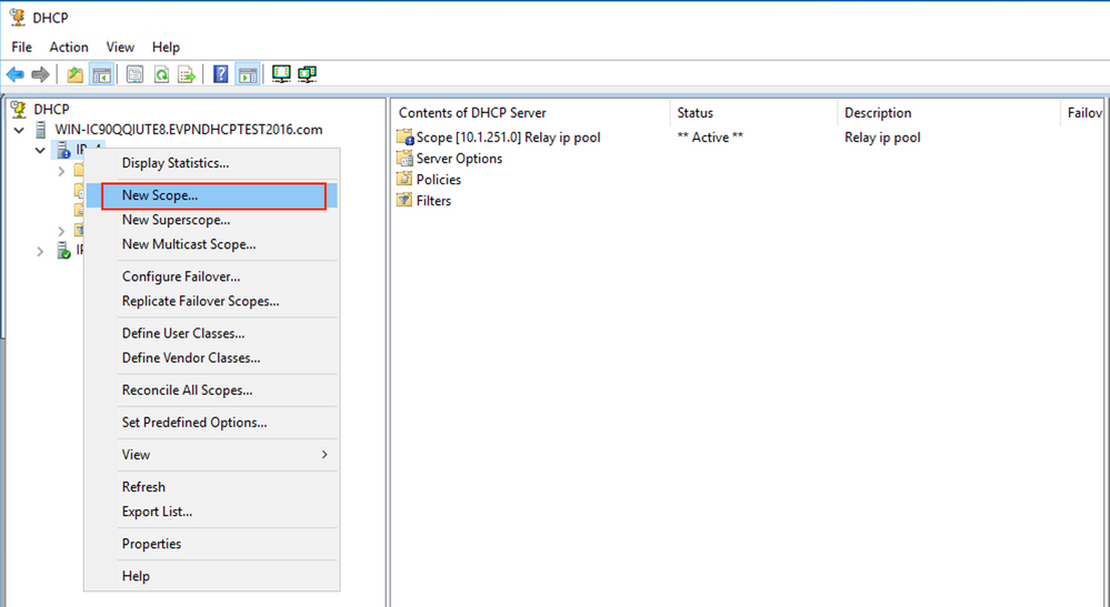
- Right-click and choose New Scope as shown in the image.
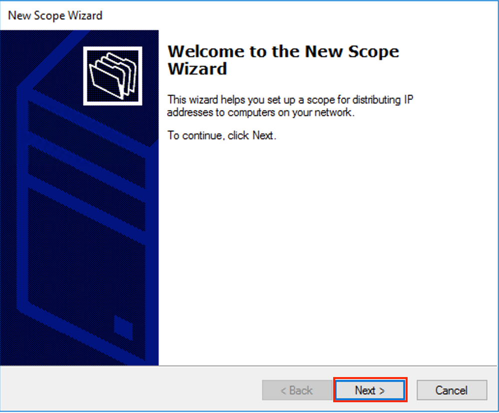
 Select Next as shown in the image.
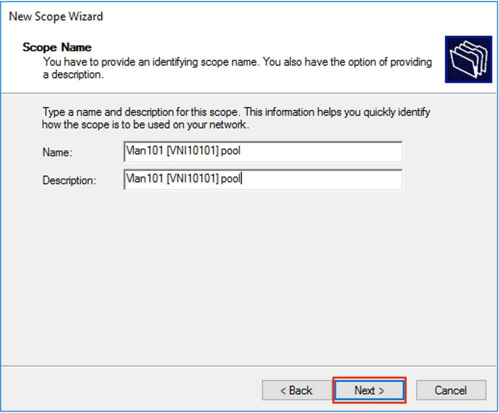
 Choose a meaningful name and description for the pool as shown in the image.
 Enter the IP address space for allocation in vlan101 as shown in the image.
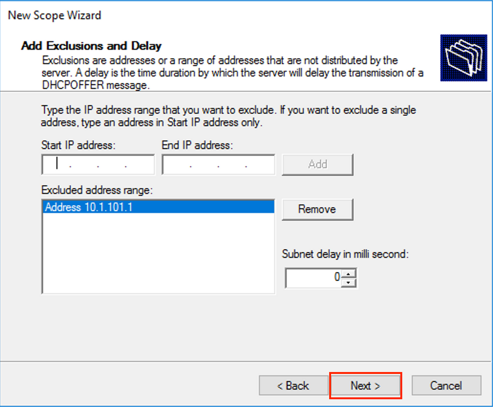
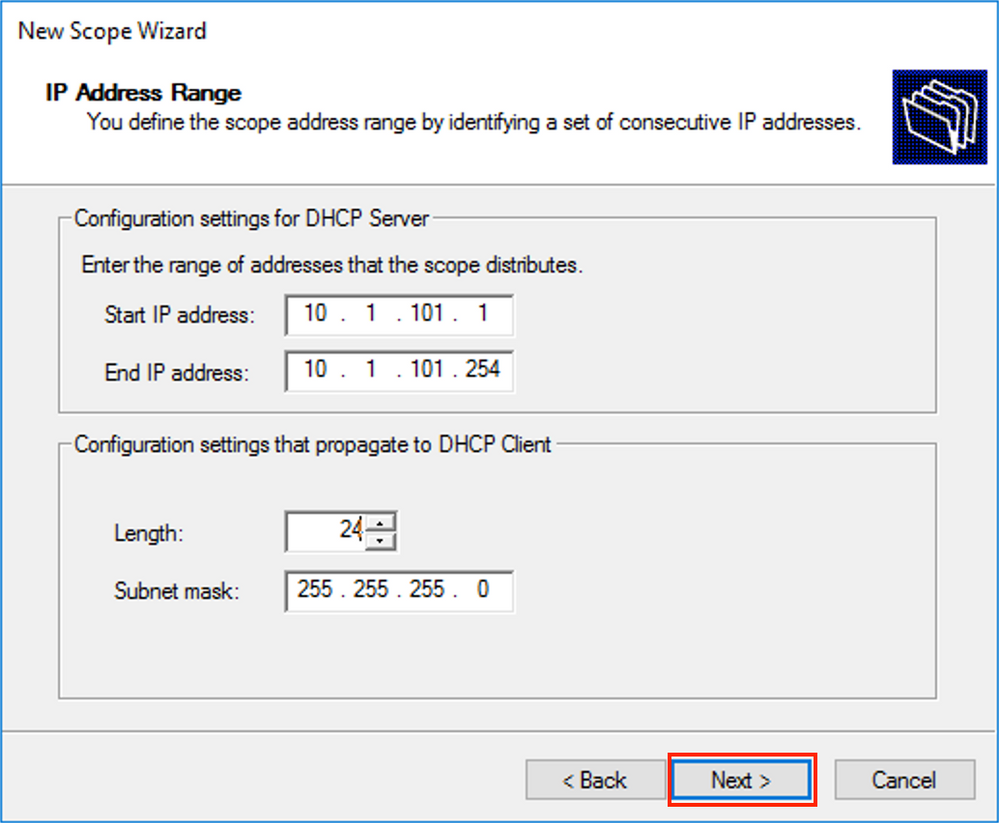 Exclude default gateway IP from the scope as shown in the image.
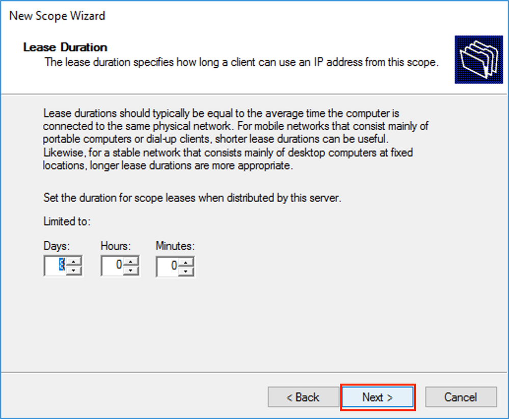
Set a Lease time as shown in the image.
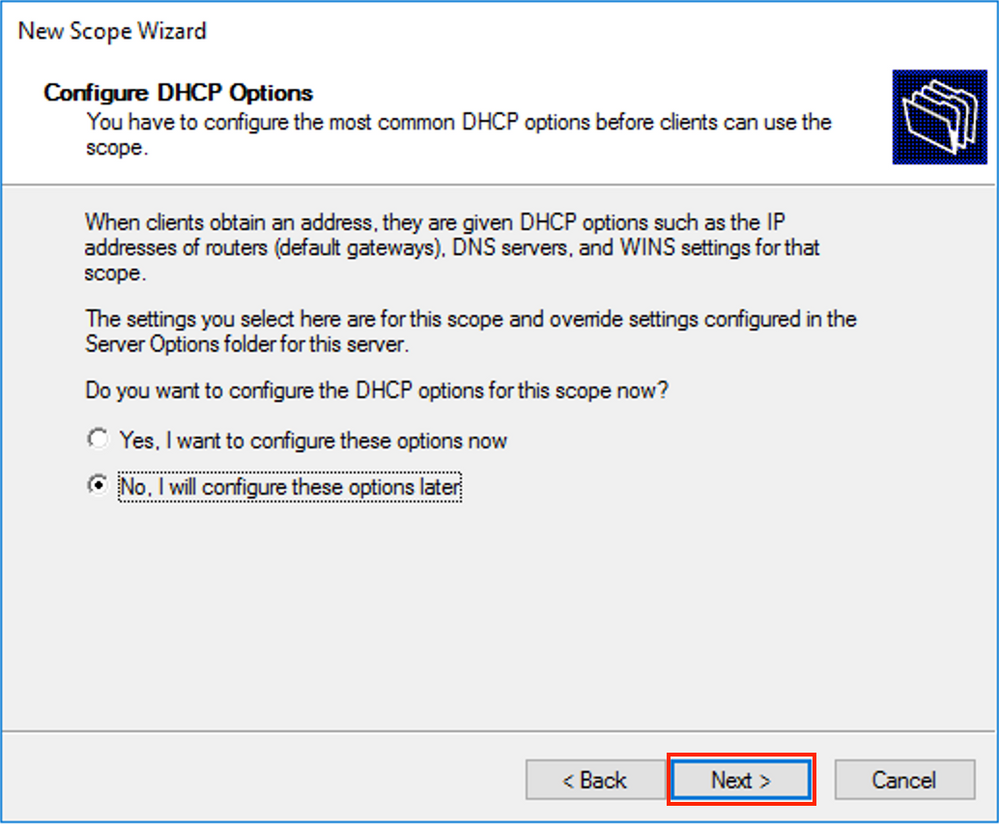
 Additional parameters like DNS/WINS and more can be configured (skipped in this example) as shown in the image.
 Select Finish to complete the setup as shown in the image.
The pool per relay IP address is not configured and is not matched in HEX. Pool selection is based on the suboption Link selection.
A new pool can be added, and no additional configuration is needed as shown in the image.

Linux DHCP Server
Review the configuration for the isc-dhcp-server on Linux.
- It supports Relay option 82. Here, the most important one is the link-selection suboption. You still can work Agent Circuit ID information and hex mask/match for the specific field (like it was done for the win2012). From a practical perspective, it is much easier to use 82[5] than work with Agent Circuit ID information directly.
- Configuration of link-selection suboption is done under the subnet definition.
In this example, the ISC server is used on Ubuntu Linux.
Install the DHCP server:
apt-get install isc-dhcp-server
In order to configure the DHCP server edit /etc/dhcp/dhcpd.conf. (Vim editor is used in an example)
vim /etc/dhcp/dhcpd.conf
Configuration snip (general configurations are omitted):
subnet 10.1.101.0 netmask 255.255.255.0 {

  option agent.link-selection 10.1.101.0;  <<< suboption 82[5] definition

  option routers 10.1.101.1;
  option subnet-mask 255.255.255.0;

  range 10.1.101.16 10.1.101.254;
}

subnet 10.1.102.0 netmask 255.255.255.0 {

  option agent.link-selection 10.1.102.0;  <<< suboption 82[5] definition

  option routers 10.1.102.1;
  option subnet-mask 255.255.255.0;

  range 10.1.102.16 10.1.102.254;
}

subnet 10.2.201.0 netmask 255.255.255.0 {

  option agent.link-selection 10.2.201.0;  <<< suboption 82[5] definition

  option routers 10.2.201.1;
  option subnet-mask 255.255.255.0;

  range 10.2.201.16 10.2.201.254;
}

subnet 10.2.202.0 netmask 255.255.255.0 {

  option agent.link-selection 10.2.202.0;  <<< suboption 82[5] definition

  option routers 10.2.202.1;
  option subnet-mask 255.255.255.0;

  range 10.2.202.16 10.2.202.254;
}
Switch Configuration
Scenarios that are supported in general are reviewed here.
-
DHCP client is in the tenant VRF and the DHCP server is in the Layer 3 default VRF
-
DHCP client is in the tenant VRF and the DHCP server is in the same tenant VRF
-
DHCP client is in the tenant VRF and the DHCP server is in a different tenant VRF
-
DHCP client is in the tenant VRF and the DHCP server is in a non-default non-VXLAN VRF
For any of these scenarios DHCP relay configuration is needed on the switch side.
The DHCP configuration for simplest option number 2.
ip dhcp relay information option      <<< Enables insertion of option 82 into the packet
ip dhcp relay information option vpn  <<< Enables insertion of vpn name/id to the packet - option 82[151]
By default, option 82 suboptions Link Selection and Server ID Override are Cisco proprietary by default (150 and 152 respectively).

If for any reason DHCP server does not understand Cisco proprietary options, you can change it to the standard one.
ip dhcp compatibility suboption link-selection standard <<< "Link Selection" suboption
ip dhcp compatibility suboption server-override standard <<< "Server ID Override" suboption

DHCP snooping must be enabled for necessary VLANs.
ip dhcp snooping vlan 101-102,201-202
ip dhcp snooping
You can use the DHCP-relay source-interface global configuration.
ip dhcp-relay source-interface Loopback101
Or you can configure it per-interface basis (the interface configuration overrides the global one).
interface Vlan101
  vrf forwarding green
  ip dhcp relay source-interface Loopback101 <<< DHCP source-interface
  ip address 10.1.101.1 255.255.255.0
  ip helper-address 192.168.20.20
Check that there is IP connectivity b/w relay IP address and DHCP server in both directions.
Leaf-01#ping vrf green 192.168.20.20 source lo101
Type escape sequence to abort.
Sending 5, 100-byte ICMP Echos to 192.168.20.20, timeout is 2 seconds:
Packet sent with a source address of 10.1.251.1
!!!!!
Success rate is 100 percent (5/5), round-trip min/avg/max = 1/1/1 ms
Under interface configuration, the address of the DHCP server is configured. It can be 3 options for this command. The client and server are in the same VRF:
interface Vlan101
  vrf forwarding green
  ip dhcp relay source-interface Loopback101
  ip address 10.1.101.1 255.255.255.0
  ip helper-address 192.168.20.20         <<< DHCP server ip address
The client and server are in the different VRFs (client in green, server in red in this example):
interface Vlan101
  vrf forwarding green
  ip dhcp relay source-interface Loopback101
  ip address 10.1.101.1 255.255.255.0
  ip helper-address vrf red 192.168.20.20   <<< DHCP server is reachable over vrf RED
end
Client in a VRF, and server in the Global Routing Table (GRT):
interface Vlan101
  vrf forwarding green
  ip dhcp relay source-interface Loopback101
  ip address 10.1.101.1 255.255.255.0
  ip helper-address global 192.168.20.20  <<< DHCP server is reachable over global routing table
end
Now, a typical configuration for all options is reviewed here.
DHCP Client is in the Tenant VRF and the DHCP Server is in the Layer 3 Default VRF
In this case, Lo0 in GRT is a relay source. DHCP relay is configured globally + for some interfaces.
For example, for the vlan101 command "IP DHCP relay source-interface Loopback0" is missed, but it uses the global configuration.
ip dhcp-relay source-interface Loopback0                 <<< DHCP relay source interface is Lo0
ip dhcp relay information option vpn                     <<< adds the vpn suboption to option 82
ip dhcp relay information option                         <<< enables DHCP option 82
ip dhcp compatibility suboption link-selection standard  <<< switch to standard option 82[5]
ip dhcp compatibility suboption server-override standard <<< switch to standard option 82[11]
ip dhcp snooping vlan 101-102,201-202                    <<< enables dhcp snooping for vlans
ip dhcp snooping                                         <<< enables dhcp snooping globally
!
interface Loopback0
  ip address 172.16.255.3 255.255.255.255
  ip ospf 1 area 0
!
interface Vlan101
  vrf forwarding green
  ip address 10.1.101.1 255.255.255.0
  ip helper-address global 192.168.20.20           <<< DHCP is reachable over GRT
!
interface Vlan102
  vrf forwarding green
  ip dhcp relay source-interface Loopback0
  ip address 10.1.102.1 255.255.255.0
  ip helper-address global 192.168.20.20           <<< DHCP is reachable over GRT
!
interface Vlan201
  vrf forwarding red
  ip dhcp relay source-interface Loopback0
  ip address 10.2.201.1 255.255.255.0
  ip helper-address global 192.168.20.20           <<< DHCP is reachable over GRT
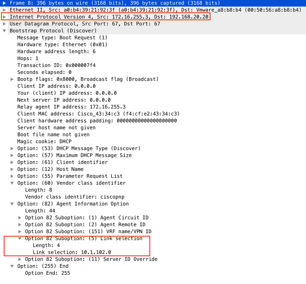
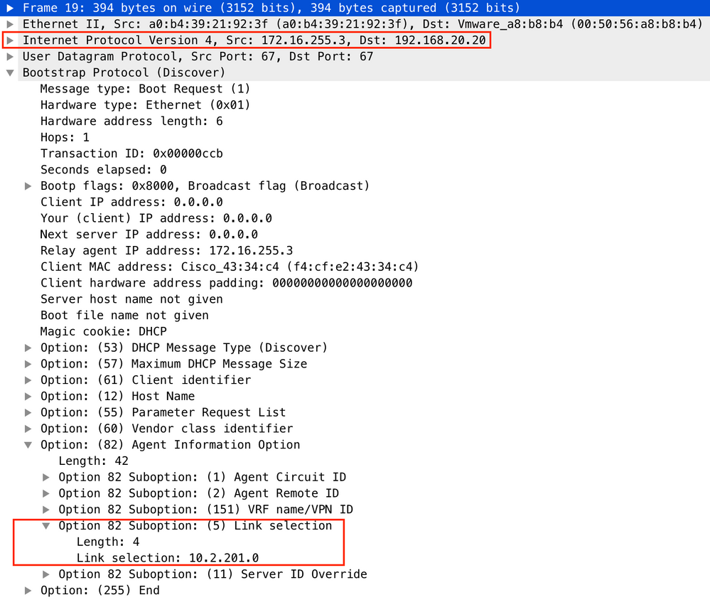
As a result, the DHCP Relay packet is sent over GRT with the same SRC IP/DST IP, but with different suboptions.
For vlan101:
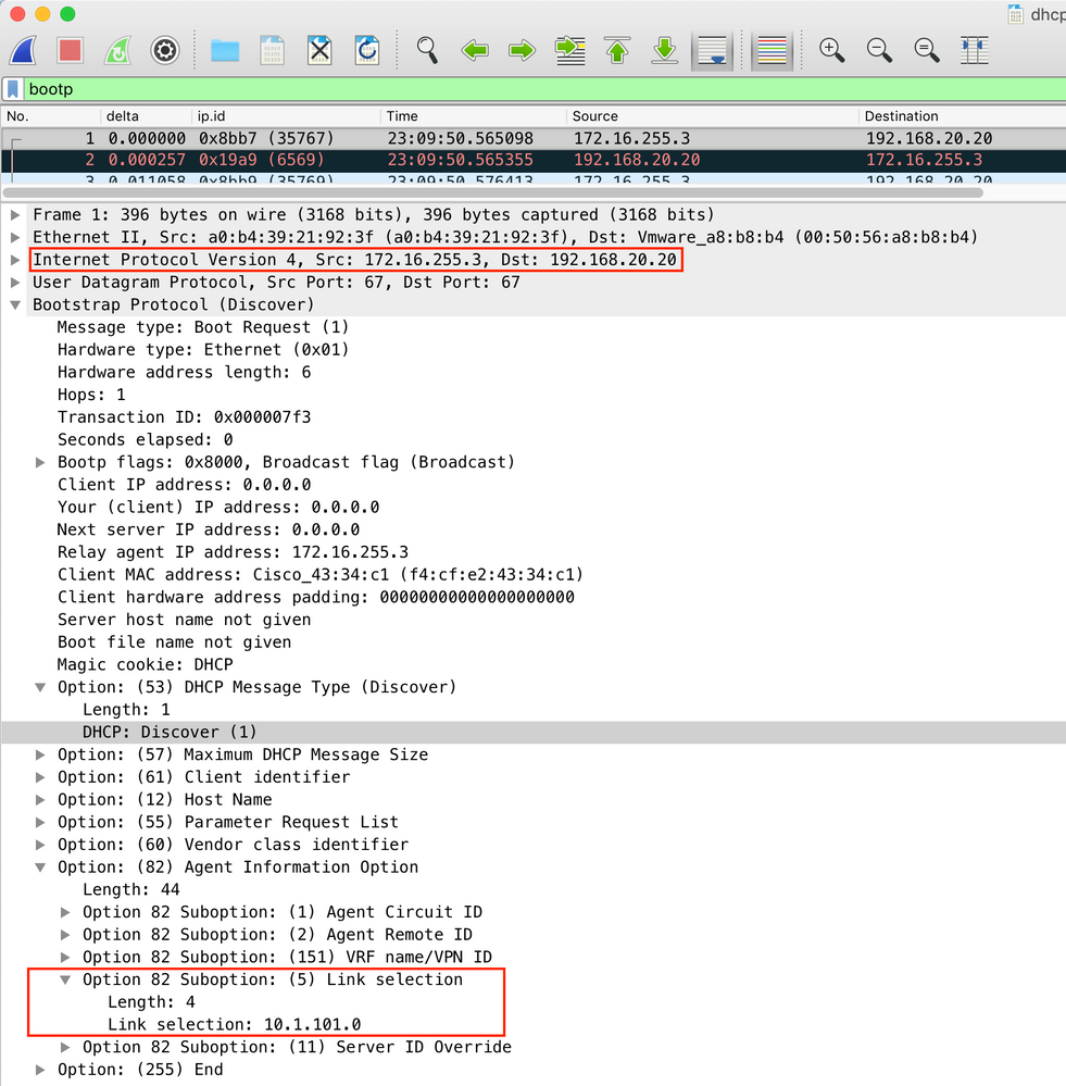
- For Vlan102:
For Vlan201 (which is in vrf red, not green like VLANs 101 and 102):
Packet capture was taken on Spine-01 from the interface to the Leaf-01:
Spine-01#sh mon cap TAC buff br | i DHCP
5401 4.402431 172.16.255.3 b^F^R 192.168.20.20 DHCP 396 DHCP Discover - Transaction ID 0x1feb
5403 4.403134 192.168.20.20 b^F^R 172.16.255.3 DHCP 362 DHCP Offer - Transaction ID 0x1feb
5416 4.418117 172.16.255.3 b^F^R 192.168.20.20 DHCP 414 DHCP Request - Transaction ID 0x1feb
5418 4.418608 192.168.20.20 b^F^R 172.16.255.3 DHCP 362 DHCP ACK - Transaction ID 0x1feb
The DHCP packet in the core is IP without any VXLAN encapsulation:
Spine-01#sh mon cap TAC buff det | b Frame 5401:
Frame 5401: 396 bytes on wire (3168 bits), 396 bytes captured (3168 bits) on interface 0
<...skip...>
[Protocols in frame: eth:ethertype:ip:udp:dhcp]
Ethernet II, Src: 10:b3:d5:6a:8f:e4 (10:b3:d5:6a:8f:e4), Dst: 7c:21:0d:92:b2:e4 (7c:21:0d:92:b2:e4)
<...skip...>
Internet Protocol Version 4, Src: 172.16.255.3, Dst: 192.168.20.20
<...skip...>
User Datagram Protocol, Src Port: 67, Dst Port: 67
<...skip...>
Dynamic Host Configuration Protocol (Discover)
<...skip...>
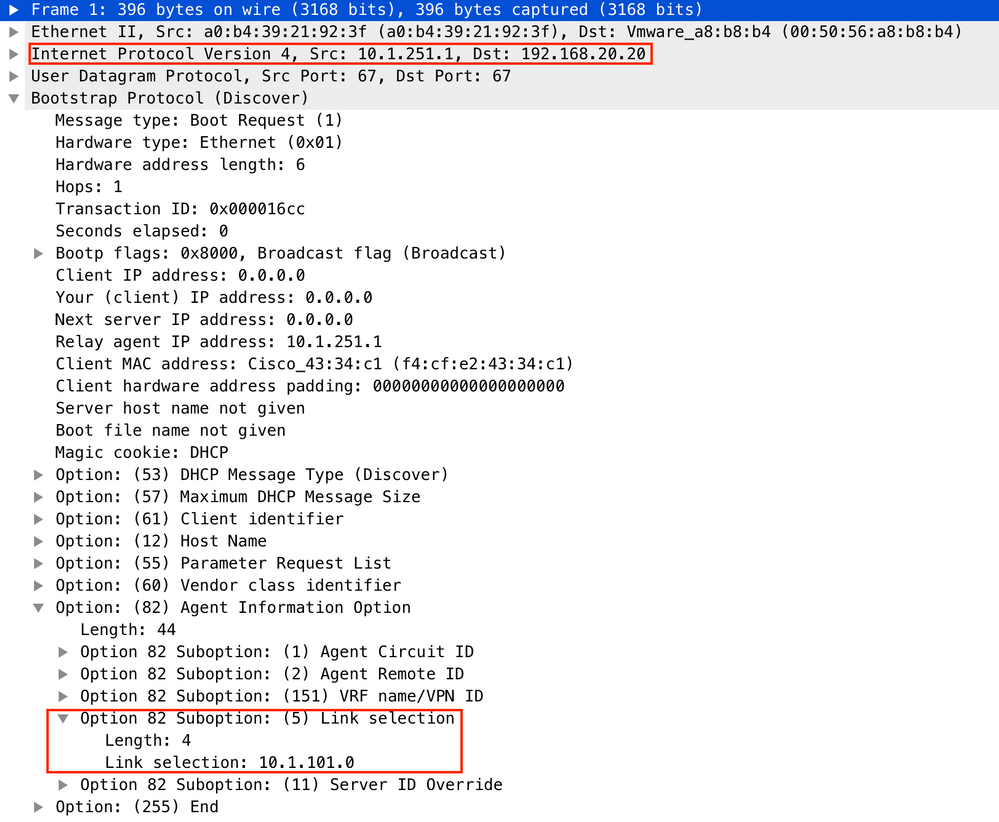
A big advantage of this approach is that you can use the same Relay IP address for different tenant VRFs without route leaking between different VRFs and global.
DHCP Client and DHCP Server are in the Same Tenant VRF
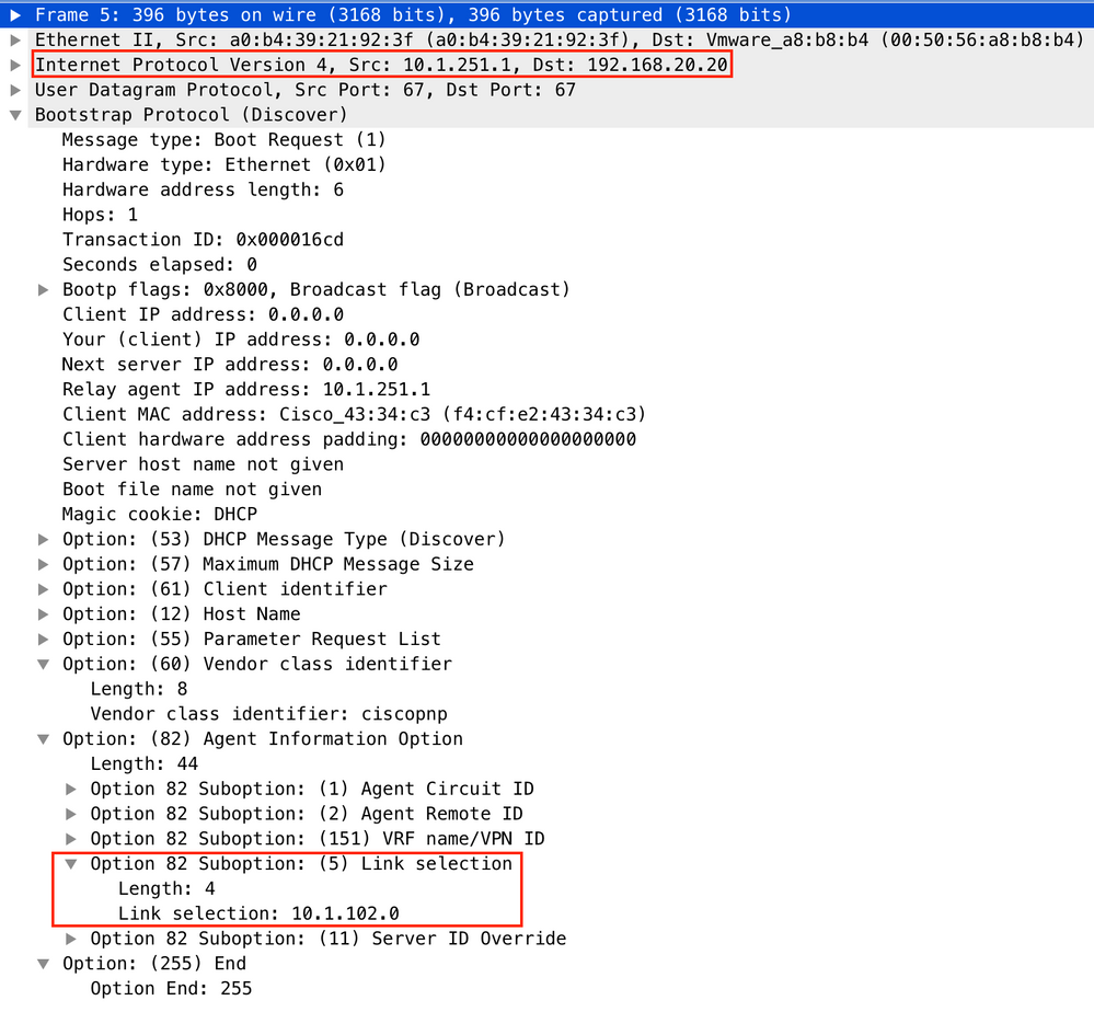
In this case, it makes sense to have the Relay IP address in the Tenant VRF.
Switch configuration:
ip dhcp relay information option vpn                     <<< adds the vpn suboption to option 82
ip dhcp relay information option                         <<< enables DHCP option 82
ip dhcp compatibility suboption link-selection standard  <<< switch to standard option 82[5]
ip dhcp compatibility suboption server-override standard <<< switch to standard option 82[11]
ip dhcp snooping vlan 101-102,201-202                    <<< enables dhcp snooping for vlans
ip dhcp snooping                                         <<< enables dhcp snooping globally
!
interface Loopback101
  vrf forwarding green
  ip address 10.1.251.1 255.255.255.255
!
interface Vlan101
  vrf forwarding green
  ip dhcp relay source-interface Loopback101
  ip address 10.1.101.1 255.255.255.0
  ip helper-address 192.168.20.20                      <<< DHCP is reachable over vrf green
!
interface Vlan102
  vrf forwarding green
  ip dhcp relay source-interface Loopback101
  ip address 10.1.102.1 255.255.255.0
  ip helper-address 192.168.20.20                      <<< DHCP is reachable over vrf green
For vlan101:
For vlan102:
Packet capture of the Spine-01 to Leaf-01 interface:
Spine-01#sh monitor capture TAC buffer brief | i DHCP
2 4.287466 10.1.251.1 b^F^R 192.168.20.20 DHCP 446 DHCP Discover - Transaction ID 0x1894
3 4.288258 192.168.20.20 b^F^R 10.1.251.1 DHCP 412 DHCP Offer - Transaction ID 0x1894
4 4.307550 10.1.251.1 b^F^R 192.168.20.20 DHCP 464 DHCP Request - Transaction ID 0x1894
5 4.308385 192.168.20.20 b^F^R 10.1.251.1 DHCP 412 DHCP ACK - Transaction ID 0x1894
The DHCP packet in the core has VXLAN encapsulation:
Frame 2: 446 bytes on wire (3568 bits), 446 bytes captured (3568 bits) on interface 0
<...skip...>
[Protocols in frame: eth:ethertype:ip:udp:vxlan:eth:ethertype:ip:udp:dhcp]
Ethernet II, Src: 10:b3:d5:6a:8f:e4 (10:b3:d5:6a:8f:e4), Dst: 7c:21:0d:92:b2:e4 (7c:21:0d:92:b2:e4)
<...skip...>
Internet Protocol Version 4, Src: 172.16.254.3, Dst: 172.16.254.5 <<< VTEP IP addresses
<...skip...>
User Datagram Protocol, Src Port: 65283, Dst Port: 4789
<...skip...>
Virtual eXtensible Local Area Network
Flags: 0x0800, VXLAN Network ID (VNI)
0... .... .... .... = GBP Extension: Not defined
.... .... .0.. .... = Don't Learn: False
.... 1... .... .... = VXLAN Network ID (VNI): True
.... .... .... 0... = Policy Applied: False
.000 .000 0.00 .000 = Reserved(R): 0x0000
Group Policy ID: 0
VXLAN Network Identifier (VNI): 50901 <<<<<<<<<<<< L3VNI for VRF green
Reserved: 0
<--- Inner header started --->
Ethernet II, Src: 10:b3:d5:6a:00:00 (10:b3:d5:6a:00:00), Dst: 7c:21:0d:bd:27:48 (7c:21:0d:bd:27:48)
<...skip...>
Internet Protocol Version 4, Src: 10.1.251.1, Dst: 192.168.20.20
<...skip...>
User Datagram Protocol, Src Port: 67, Dst Port: 67
<...skip...>
Dynamic Host Configuration Protocol (Discover)
<...skip...>
DHCP Client in One Tenant VRF and DHCP Server in Another Tenant VRF
In this example, the client is in vrf red and server is in vrf green.
You have two options:
- Keep Relay IP in client vrf and configure route leaking which adds more complexity
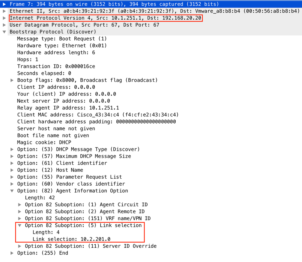
- Keep Relay IP in server vrf (similar to what you did for GRT in 1st case)
It is simpler to choose the second approach since a lot of client vrfs are supported and route leaking is not needed.
Switch configuration:
ip dhcp relay information option vpn                     <<< adds the vpn suboption to option 82
ip dhcp relay information option                         <<< enables DHCP option 82
ip dhcp compatibility suboption link-selection standard  <<< switch to standard option 82[5]
ip dhcp compatibility suboption server-override standard <<< switch to standard option 82[11]
ip dhcp snooping vlan 101-102,201-202                    <<< enables dhcp snooping for vlans
ip dhcp snooping                                         <<< enables dhcp snooping globally
!
interface Loopback101
vrf forwarding green
ip address 10.1.251.1 255.255.255.255
!
interface Vlan201
vrf forwarding red
ip dhcp relay source-interface Loopback101
ip address 10.2.201.1 255.255.255.0
ip helper-address vrf green 192.168.20.20                <<< DHCP is reachable over vrf green
For vlan201:
Packet capture on Spine-01 to Leaf-01 interface:
Spine-01#sh mon cap TAC buff br | i DHCP
2 0.168829 10.1.251.1 b^F^R 192.168.20.20 DHCP 444 DHCP Discover - Transaction ID 0x10db
3 0.169450 192.168.20.20 b^F^R 10.1.251.1 DHCP 410 DHCP Offer - Transaction ID 0x10db
4 0.933121 10.1.251.1 b^F^R 192.168.20.20 DHCP 462 DHCP Request - Transaction ID 0x10db
5 0.933970 192.168.20.20 b^F^R 10.1.251.1 DHCP 410 DHCP ACK - Transaction ID 0x10db
In this example, the packet in the core is VXLAN encapsulated.
Frame 2: 446 bytes on wire (3552 bits), 444 bytes captured (3552 bits) on interface 0
<...skip...>
[Protocols in frame: eth:ethertype:ip:udp:vxlan:eth:ethertype:ip:udp:dhcp]
Ethernet II, Src: 10:b3:d5:6a:8f:e4 (10:b3:d5:6a:8f:e4), Dst: 7c:21:0d:92:b2:e4 (7c:21:0d:92:b2:e4)
<...skip...>
Internet Protocol Version 4, Src: 172.16.254.3, Dst: 172.16.254.5  <<< VTEP IP addresses
<...skip...>
User Datagram Protocol, Src Port: 65283, Dst Port: 4789
<...skip...>
Virtual eXtensible Local Area Network
Flags: 0x0800, VXLAN Network ID (VNI)
0... .... .... .... = GBP Extension: Not defined
.... .... .0.. .... = Don't Learn: False
.... 1... .... .... = VXLAN Network ID (VNI): True
.... .... .... 0... = Policy Applied: False
.000 .000 0.00 .000 = Reserved(R): 0x0000
Group Policy ID: 0
VXLAN Network Identifier (VNI): 50901                              <<< L3VNI for VRF green
Reserved: 0
<--- Inner header started --->
Ethernet II, Src: 10:b3:d5:6a:00:00 (10:b3:d5:6a:00:00), Dst: 7c:21:0d:bd:27:48 (7c:21:0d:bd:27:48)
<...skip...>
Internet Protocol Version 4, Src: 10.1.251.1, Dst: 192.168.20.20
<...skip...>
User Datagram Protocol, Src Port: 67, Dst Port: 67
<...skip...>
Dynamic Host Configuration Protocol (Discover)
<...skip...>
DHCP Client in One Tenant VRF and DHCP Server in Another Non-VXLAN VRF
This case is very similar to the last one. The key difference is that packets do not have VXLAN encapsulation - pure IP or something else (MPLS/GRE/etc), but it is the same from a configuration perspective.
In this example, the client is in vrf red and the server is in vrf green.
You have two options:
- Relay IP is in the client vrf and configures route leaking which adds more complexity
- Relay IP is in the server vrf (similar to what was done for GRT in the 1st case)
It is simpler to choose the second approach as a lot of client vrfs are supported and route leaking is not needed.
Switch Configuration:
ip dhcp relay information option vpn                     <<< adds the vpn suboption to option 82
ip dhcp relay information option                         <<< enables DHCP option 82
ip dhcp compatibility suboption link-selection standard  <<< switch to standard option 82[5]
ip dhcp compatibility suboption server-override standard <<< switch to standard option 82[11]
ip dhcp snooping vlan 101-102,201-202                    <<< enable dhcp snooping for vlans
ip dhcp snooping                                         <<< enable dhcp snooping globally
!
interface Loopback101
vrf forwarding green
ip address 10.1.251.1 255.255.255.255
!
interface Vlan201
vrf forwarding red
ip dhcp relay source-interface Loopback101
ip address 10.2.201.1 255.255.255.0
ip helper-address vrf green 192.168.20.20               <<< DHCP is reachable over vrf green
Related Information
Revision History
| Revision | Publish Date | Comments |
|---|---|---|
3.0 |
06-Jul-2022 |
Rectified an IP address on the ladder diagram. |
2.0 |
14-Sep-2021 |
Adjusted IOS-XE to IOS XE in title |
1.0 |
13-Sep-2021 |
Initial Release |
Contributed by Cisco Engineers
- Dmytro VishchukCisco Technical Leader
Contact Cisco
- Open a Support Case

- (Requires a Cisco Service Contract)
 Feedback