Catalyst 5000 and Catalyst 3900 Frequently Asked Questions
Available Languages
Contents
Introduction
This document provides information in the form of an FAQ for the Catalyst 3900 and 5000 family. It contains troubleshooting information, new features with latest software revisions and some design and connectivity guidelines.
Refer to Cisco Technical Tips Conventions for more information on document conventions.
Q. Can ISL be used parallel to ATM between two Catalyst 3900 switches?
A. Because the Catalyst 3900 supports the propagation of LAN turning information through ILL connections only, it is important that the ILL connection be the active path in an ISL-ATM parallel connection. If the ISL module is configured in parallel connections with ATM or Token Ring, the STP allows only one active port at a time. When the default Catalyst 3900 STP values are used, the path cost is calculated based on a 200-Mbps connection that results in a path cost of five and causes the STP to place the ISL port in forwarding mode and the ATM port or the Token Ring port in blocked mode.
However, if you modify the Catalyst 3900 port STP values or use devices from other vendors that use different STP values, it can block the ISL port. If an ISL port becomes blocked in an ISL-ATM parallel connection, traffic passes through the ATM link, but VLAN trunking data is not passed. Also, if your STP configuration makes an ATM or Token Ring port the forwarding path to the root switch instead of the ISL link, the switch on the other end of a blocked ISL port can incorrectly limit AREs to the inbound TrCRF. Therefore, when you modify STP values, always ensure that the STP port path costs are configured so that the ISL port is the preferred path. In an ISL parallel configuration, a Token Ring or ATM link must never have a lower cost to the root bridge than the ISL link.
Q. Why do the QTP_FSM: Port x: QMAC Not Responding.... and, QTP_Task(): CmdDone not expected here messages appear in the message log on Catalyst 3900?
A. These messages are caused by an error condition that most likely occurs when the switch is connected to a ring that reports many errors. Some ports are not operational after this message is displayed. This is fixed in version 3.0(6)-- of Catalyst 3900 and later.
Q. What is VTP pruning and is it supported on the Catalyst 3900?
A. VTP pruning is used in order to prevent unnecessary flooding of broadcast information from one vlan across all trunks, since the switches do not know which vlans exist in a remote switch. VTP pruning permits switches to negotiate which vlans are assigned to ports at the other end of a trunk and hence, prune the vlans that are not assigned remotely. Pruning is disabled by default. Pruning is supported in Catalyst 3900 version 4.1(1) and later.
Q. Where can I find a document with most of the Token Ring Switching acronyms?
A. Refer to Token Ring Switching Acronyms for a list of acronyms.
Q. How can I connect a Catalyst 5000 to a Catalyst 3900 with ISL?
A. The Catalyst 3900 switch can be connected to the Catalyst 5000 through the dual 100-Mbps ISL expansion module. The Catalyst 3900 Token Ring switch does not support any mode other than ISL, so it is always trunked. The Catalyst 3900 ISL modules also only support a 100 Mb connection and default to full duplex.
Be very careful when you connect a Catalyst 3900 and a Catalyst 5000 switch through the ISL link. The main problem is that the Catalyst 3900 does not support Fast Ethernet media negotiation. For this reason, if the Catalyst 5000 is configured for AUTO, it defaults to 100 Mb half duplex. This causes problems, such as the port changing from trunk to non trunk and packet loss.
If you want to attach the Catalyst 3900 ISL port to the ISL port of a Catalyst 5000, you must manually configure the ISL port on the Catalyst 5000 for 100 Mbps with the set port speed command:
Usage: set port speed <mod/port> <4|10|16|100|auto>and full-duplex using the set port duplex command:
Usage: set port duplex <mod/port> <full|half>
Q. What is DRiP and how does it work?
A. DRiP is Cisco Duplicate Ring Protocol and its job is to ensure the proper configuration of Token Ring VLANs and to create explorer reduction. One of the most important features of DRiP is to enforce TrCRF distribution. In the Token Ring world, distributing any VLAN other than 1003 is very dangerous because of spanning issues. For this reason, if a TrCRF other than VLAN 1003 is distributed, all ports to which that VLAN is associated are disabled by DRiP. Refer to Duplicate Ring Protocol for more information.
Q. How can I use HSRP with Token Ring switches?
A. Hot Standby Router Protocol (HSRP) uses a multicast destination address in the network. Since nobody in the network actually sources packets with this multicast address, the switches never learn these MAC addresses and hence, flood frames throughout the network. In order to overcome this problem, use a MAC address that can actually be used as a SMAC by the routers in the HSRP hellos. This allows the switches to learn this address and switch the packets appropriately. In order to do this, configure a new "virtual" MAC address in the routers. Clients need to send packets to the DMAC of this new virtual address. Here is the output of show standby.
vdtl-rsm#show stand

Vlan500 - Group 10

Local state is Active, priority 100

Hellotime 3 holdtime 10

Next hello sent in 00:00:01.224

Hot standby IP address is 1.1.1.100 configured
Active router is local
Standby router is unknown expired
Standby virtual mac address is 0000.0c07.ac0a
From this display, a standby group 10 (standby ip 10 1.1.1.100) is created. The MAC address (0000.0c07.ac0a) is basically the new virtual MAC address and the last byte is the group (0xA = 10). Now because the router sources packets with the DMAC of the HSRP virtual MAC, the switches learn this MAC address and only forward the packets to the active HSRP router. In the case when the active HSRP router fails and the standby goes active, the new active router initiates sending HSRP hellos with the same SMAC, which causes the switch MAC address tables to switch over their learned entries to the new switch port/trunk.
Refer to HSPR with Token Ring Switches for more information.
Q. What is the most common cause for a Catalyst 3900 Stack to split?
A. The two most common causes for a stack split are:
one switch in the stack is reset
very heavy traffic goes through the stack backbone
The former can be caused by a switch crash or manual reset. In either case, further investigation is required in order to prevent future reoccurence. The latter problem is caused by very heavy broadcast traffic, which causes the heartbeat signal, (used as a keepalive for the stack to stay joined) to timeout. Increase the stack timeout value in order to resolve this issue. The default is 16 seconds and the maximum is 65535 seconds. It is also important to ensure that the latest Catalyst 3900 revision is run. Check Cisco.com in order to confirm this.
Q. Can the Catalyst 3900/3920 and Catalyst 5000/5500 detect soft errors on a per port basis and isolate the offending station?
A. The Catalyst 3900/3920 Switch Software Release 4.1(1) and later performs error detection and isolation by monitoring the Report Soft Error MAC frames generated by stations on each port. Soft errors occur during normal ring operation and do not typically disrupt traffic on the ring. However, soft errors can occur at a rate that can potentially degrade the performance of the ring. If you use the Catalyst 3900 or Catalyst 3920, you can configure soft error thresholds and sampling intervals for a port. During the interval you define, the Catalyst 3900 monitors the stations on the port. If the threshold is exceeded, the switch can be configured to generate a trap that indicates the port number and station on which the threshold is exceeded. If necessary, you can issue a Remove Ring Station MAC frame in order to remove the station from the ring. Refer to Configuring Soft Error Monitoring for Catalyst 3900 for more information.
The Catalyst 5000/5500 Token Ring Blade Software Release 3.1(1) and later also performs error detection and isolation by monitoring the Report Soft Error MAC frames generated by stations on each port. Refer to Configuring Soft Error Monitoring in the Configuring Token Ring Switching for Catalyst 5000 Guide for more information.
Q. Is there a way to reduce Explorers on the Catalyst 5000 and 3900 switches?
A. In release 3.2(3) of the Token Ring Blade in the Catalyst 5000 family, the number of explorer frames forwarded by a Token Ring port can be configured. This is important in networks that have a significant amount of explorer frames that impact the network. Issue the set tokenring explorer-throttle command in order to control the number of inbound explorer frames per second allowed on a Token Ring module port. For the Catalyst 3900 and 3920 there is an option called Max Explorer rate under port configuration. Refer to Configuring Port Parameters in the Catalyst 3900 Configuration Guide.
Q. How do I design a redundant switched backbone?
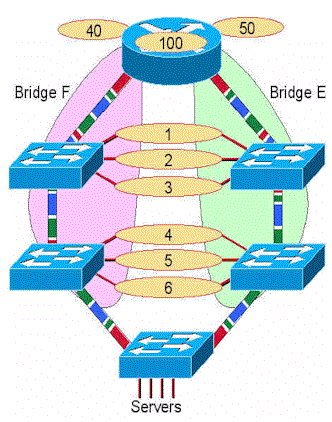
A. The simplest and most effective way to do this is to provide two (and only two) paths from each ring to every other ring. This is a picture of four switches in a parallel backbone. In this diagram, there are two completely parallel paths. The two sides of the network do not have to be interconnected with ISL or ATM. This only adds complexity with no gain in availability. Each side of the network is a different TrBRF VLAN. For each ring, there is a TrCRF on each side of the network with the same ring number, but not the same VLAN id. You can make the VLAN ID the same if you make sure that the two halves of the network are not interconnected with VTP. In order to connect servers directly to the switch, use a separate switch that is then connected to both halves of the backbone with ISL. In order to connect to the router with ISL, two links can be used, as shown:

Q. How does RI-RO support work on the Catalyst 3900 and 5000 switches?
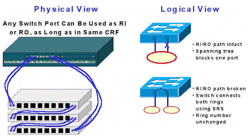
A. Ring In/Ring Out (RI/RO) support is provided on the fiber Token Ring ports on both the Catalyst 3900 and 5000. In addition, ports 19 and 20 of the Catalyst 3900 support RI/RO. These ports can be used in order to connect to IBM 8230 compatible RI/RO ports on hubs. This diagram shows how this works. If the switch is connected to both the RI and RO port of a hub, it provides a backup capability in case a link between hubs is broken. In the normal case, there is a single ring connected to two switch ports and spanning tree will block one of the ports. If the ring breaks, there is now two rings that are bridged together with SRS (the two ports must be defined in the same CRF). Therefore, the ring is healed and now has twice the bandwidth. It is not necessary to connect both the RI and RO, unless redundancy is desired. Note also, that the switch signals the hub to wrap the RI or RO port if only the transmit fiber from the hub to the switch is cut. This ensures that the hub maintains the integrity of the ring.

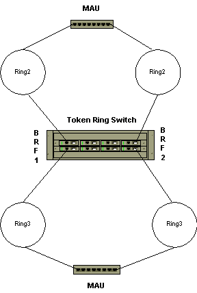
Q. Why can't I configure the typical parallel bridge scenario below?
A. This is a valid scenario. If done in a single switch, two TrBRF VLANs (with different bridge numbers) are defined with two TrCRF VLANs each (ring 2 and ring 3). The ports are then connected to the MAUs. This simply appears as two parallel bridges between the rings. Spanning Tree prevents loops in this configuration.
Note: There is no direct connection within the switch between TrBRF 1 and TrBRF 2.
Q. How do you configure redundancy for ISL in a Token Ring network?

A. ISL backup of another ISL connection is configured by default. All ISL ports are configured by default to trunk all VLANs. Spanning Tree blocks redundant paths between multiple ISL ports. Spanning Tree allows the automatic configuration of backup ISL paths.
Q. Why does the entire TokenChannel go down if a single link fails in the Catalyst 3900?
A. This limitation is removed in release 4.1.1., when fault-tolerant Channels are added (TokenChannel and ISL Channel). The fault-tolerant feature enables TokenChannel and ISL Channel configurations to function as long as there is at least one port active in the channel. This capability ensures that large portions of a network are not disrupted in the event a port or cable fails within the channel by transferring the traffic to one or more of the remaining ports in the channel.
Q. What type of errors cause the Catalyst 3900 to switch to store-and-forward?
A. The decision to transition between cut-thru and store-and-forward when a port is configured for "auto" is based on the percentage of errored frames to all frames seen on that port during the sampling interval. Errored frames are:
Frames with CRC errors
Aborted frames
Frames that are too short
At the end of a sampling interval, a calculation is done to determine the percentage of these errored frames to all frames seen on the port. If the resulting percentage is greater than the "error high threshold", the port goes to store-and-forward mode. If the percentage is lower than the "error low threshold", the port goes to cut-thru mode.
The sampling interval, the error high threshold, and the error low threshold are all configurable on the Port Configuration panel. The defaults are:
sampling interval: 10 minutes

error high threshold: 10%

error low threshold: 1%
Q. Can Ethernet be tunneled over the Catalyst 3900 ISL links?
A. No. Pass-thru of Ethernet traffic from one ISL port to another on the Catalyst 3900 is not supported. In addition, the Catalyst desktop Ethernet switches that support ISL do NOT support Token Ring ISL passthrough.
Q. What Catalyst 5000 Fast Ethernet and Gigabit modules support TRISL?
A. Catalyst 5000 Modules That Support TRISL
Product Number Product Description Max Frame Size Comments WS-X5505 Catalyst 5500/5000 Series Supervisor Engine II FX-SMF 17800 WS-X5506 Catalyst 5500/5000 Series Supervisor Engine II FX-MMF 17800 WS-X5509 Catalyst 5500/5000 Series Supervisor Engine II TX and MII 17800 @ 10M 8905 @100M See Note 2 WS-U5531-FETX Dual port 100BaseTX Uplink module for Supervisor III 17800 @ 10M 8905 @100M See Notes 1 and 2 WS-U5533-FEFX-MMF Dual port 100BaseFX MMF Uplink module for Supervisor III 17800 See Note 1 WS-U5535-FEFX-SMF Dual port 100BaseFX SMF Uplink module for Supervisor III 17800 See Note 1 WS-U5534-GESX Dual port 1000BaseSX Uplink module for Supervisor III (Pronto) 17800 WS-X5213A Catalyst 5000 Fast Ethernet switching module (10/100BaseTX, 12 interfaces) 17800 @ 10M 8905 @100M See Notes 1 and 2 WS-X5114 Catalyst 5000 Fast Ethernet switching module (100BaseFX, 12 interfaces, 6 multimode/6 single mode) 17800 See Note 1 WS-X5225R Catalyst 5000 24-port 10/100BaseTX Backbone Fast EtherChannel? Switching Module (802.1Q/ISL, RJ-45) 17800 @ 10M 8905 @100M See Notes 1 and 2 WS-X5203 Catalyst 5000 Fast EtherChannel switching module (10/100BaseTX, 12 interfaces) 17800 @ 10M 8905 @100M See Notes 1 and 2 WS-X5201 Catalyst 5000 Fast EtherChannel switching module (100BaseFX, 12 interfaces) 17800 See Note 1 WS-X5201R Catalyst 5000 12-port 100BaseFX Backbone Fast EtherChannel Switching Module (802.1Q/ISL, SC) 17800 See Note 1 WS-X5403 Catalyst 5000 3-port Gigabit Ethernet Switching Module 17800 WS-U5536-GELX Dual port 1000BaseLX Uplink module for Supervisor III 17800 WS-X5534-E1-GESX Sup III module with built in WS-U5534-GESX 17800 WS-X5536-E1-GELX Sup III module with built in WS-U5536-GELX 17800 WS-X5236-FX-MT 24-port 100FX Switch Module (FEC, WRED, 802.1Q/ISL, MT-RJ (Bimini) 17800 WS-X5234-RJ45 24-port 10/100TX Switch Module (FEC, WRED, 802.1Q/ISL, RJ-45) (Cello) 8905 WS-U5537-FETX Four Port 100BaseTX Uplink Module for Supervisor Engine III) (Primo) 8905 See Note 2 WS-U5538-FEFX-MMF 4-Port 100BaseFX MMF Uplink Module for Supervisor Engine III) (Primo) 17800 WS-X5239-RJ21 36-port 10/100TX Switch Module (FEC, WRED, 802.1Q/ISL, Telco) (Tuba) 8905 Notes:
1. If you use Catalyst 3900 ISL up-links, 3900 Main Image Release 3.0(3), or later, is recommended. Also, review the Release Notes at: http://www.cisco.com/univercd/cc/td/doc/product/lan/cat3900/c39reln/index.htm
2. Fiber versions of this module supports full size 17,800 byte frames.
Q. What is the minimum Cisco IOS release to support routing of Token Ring VLANs on an RSM as well as MLS for Fast Ethernet on the same RSM/Catalyst 5000?
A. Cisco IOS Software Release 12.0(3)T is the minimum.
Q. What Routing Modules of the Cat5000/6000 family support Token Ring VLANS?
A. The Route Switch Module (RSM) is the ONLY Cat5000 routing module that supports Token Ring VLANs. The Cat5000's Route Switch Feature Card (RSFC) does NOT support Token Ring VLANs. There is NO support for Token Ring VLANs in any Cat6000 product.
Support for the Token Ring RSM feature is first introduced in Cisco IOS Software Release 11.3(5)T. The Token Ring RSM feature is supported on all RSM Cisco IOS 12.0T software release images.
Q. Is there a command on the Catalyst switches that can display a list of the order of stations by MAC address on the monitored rings?
A. Yes, on the Catalyst 5000 and 5500 in Token Ring blade release 3.2(5), you can issue the show station ordertable command in order to display a list of the order of stations on a per port basis, here is a sample display:
Pteradactyl-Sup> (enable) sh station ordertable 7/4

Port    OrderIndex         Address

-----   ---------------    -----------------

 7/4    1                  40:00:40:00:40:00

        2                  00:05:77:05:45:42
Note: For the Catalyst 3900, there is no direct way to list the order of stations.
Related Information
Contact Cisco
- Open a Support Case

- (Requires a Cisco Service Contract)


 Feedback