Total Network Configuration: RV345P and Cisco Business Wireless using the Mobile Application
Available Languages
Objective
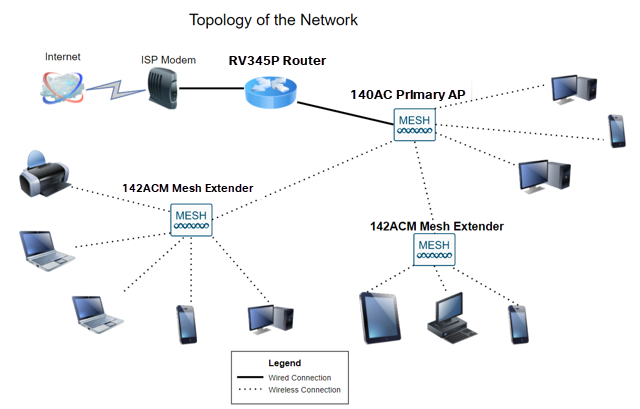
This guide will show you how to configure a wireless mesh network using an RV345P router, a CBW140AC access point, and two CBW142ACM mesh extenders.
This article uses the mobile application, which is recommended for simple set up on the mesh wireless network. If you prefer to use the Web User Interface (UI) for all configurations, click to jump to the article that uses the Web UI.
Table of Contents
- Prerequisites
- Configure the RV345P Router
- Security Options
- VPN Options
- Supplemental Configurations on the RV345P Router
- Configure the Wireless Mesh Network
- CBW140AC Out of the Box
- Set Up the 140AC Mobile Application Wireless Access Point on the Mobile Application
- Wireless Troubleshooting Tips
- Configure the CBW142ACM Mesh Extenders Using the Mobile Application
- Check and Update Software Using the Mobile Application
- Create WLANs on the Mobile Application
- Create a Guest WLAN using the Mobile Application (Optional)
- Application control allows you to control traffic. This feature can be configured to allow traffic but to log it, block traffic and log it, or simply to block traffic.
- Web Filtering is used to prevent web traffic to insecure or inappropriate web sites. There is no logging with this feature.
- AnyConnect is a Secure Sockets Layer (SSL) Virtual Private Network (VPN) that is available from Cisco. VPNs allow remote users and sites to connect to your company office or datacenters by making a secure tunnel through the Internet.
- Cisco Business: Glossary of New Terms
- Welcome to Cisco Business Wireless Mesh Networking
- Frequently Asked Questions (FAQ) for a Cisco Business Wireless Network
- RV345P | 1.0.03.21
- CBW140AC | 10.4.1.0
- CBW142ACM | 10.4.1.0 (at least one mesh extender is needed for the mesh network)
- Make sure you have a current Internet connection for setup.
- Contact your Internet Service Provider (ISP) to find out any special instructions they have when using your RV345P router. Some ISPs offer gateways with built-in routers. If you have a gateway with an integrated router, you may have to disable the router and pass the Wide Area Network (WAN) IP address (the unique Internet protocol address that the Internet provider assigns to your account) and all network traffic through to your new router.
- Decide where to place the router. You will want an open area if possible. This may not be easy because you must connect the router to the broadband gateway (modem) from your Internet Service Provider (ISP).
- Verify that your web browser is not set to Work Offline.
- Check the local area network connection settings for your Ethernet adapter. The PC should obtain an IP address through DHCP. Alternatively, the PC can have a static IP address in the 192.168.1.x range with the default gateway set to 192.168.1.1 (the default IP address of the RV345P). To connect, you may need to modify the network settings of the RV345P. If you are using Windows 10, check out Windows 10 directions to modify the network settings.
- If you have existing equipment occupying the 192.168.1.1 IP address, you'll need to resolve this conflict for the network to operate. More on this at the end of this section, or click here to be taken there directly.
- Reset the modem and the RV345P by powering off both devices. Next, power on the modem and let it sit idle for about 2 minutes. Then power on the RV345P. You should now receive a WAN IP address.
- If you have a DSL modem, ask your ISP to put the DSL modem into bridge mode.
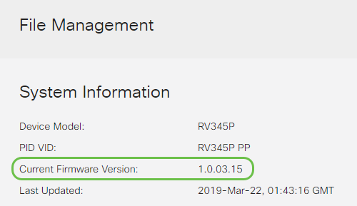
- Device Model - Displays the model of your device.
- PID VID - Product ID and Vendor ID of the router.
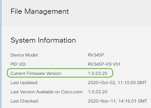
- Current Firmware Version - Firmware that is currently running on the device.
- Latest Version Available on Cisco.com - Latest version of the software available on the Cisco website.
- Firmware last updated - Date and time of the last firmware update made on the router.
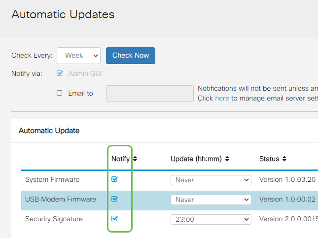
- System Firmware — The main control program for the device.
- USB Modem Firmware — The control program or driver for the USB port.
- Security Signature — This will contain signatures for Application Control to identify applications, device types, operating systems, and so on.
- Intrusion Prevention System (IPS): Inspects network packets, logs, and/or blocks a wide range of network attacks. It delivers increased network availability, faster remediation, and comprehensive threat protection.
- Antivirus: Protection from viruses by scanning the applications for various protocols like HTTP, FTP, SMTP Email attachments, POP3 Email attachments, and IMAP Email attachments going through the router.
- Web Security: Enables business efficiency and security while connecting to the Internet, allows Internet access policies for end devices and Internet applications to help ensure performance and security. It is cloud-based and contains more than 80 categories with more than 450 million domains classified.
- Application Identification: Identify and assign policies to Internet applications. 500 unique applications are automatically identified.
- Client Identification: Identify and categorizes clients dynamically. The ability to assign policies based on end-device category and operating system.
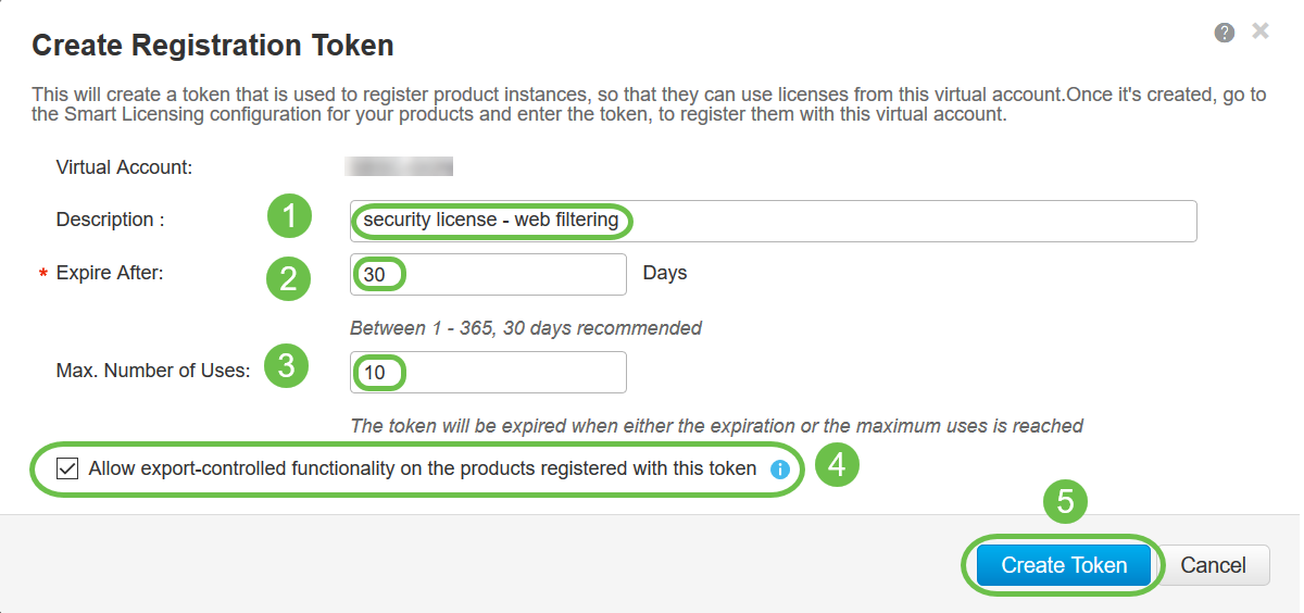
- In the Description field, enter a unique description for the token. In this example, security license – web filtering is entered.
- In the Expire After field enter a value between 1 to 365 days. Cisco recommends the value 30 days for this field; however, you may edit the value to fit your needs.
- In the Max. Number of Uses field enter a value to define the number of times you want to use that token. The token will expire when either the amount of days or the maximum number of uses is reached.
- Check the Allow export-controlled functionality on the products registered with this token checkbox to enable the export-controlled functionality for tokens of a product instance in your virtual account. Uncheck the checkbox if you do not want to allow the export-controlled functionality to be made available for use with this token. Use this option only if you are compliant with the export-controlled functionality. Some export-controlled features are restricted by the United States Department of Commerce. These features are restricted for products registered using this token when you uncheck the checkbox. Any violations are subjected to penalties and administrative charges.
- Click Create Token to generate the token.
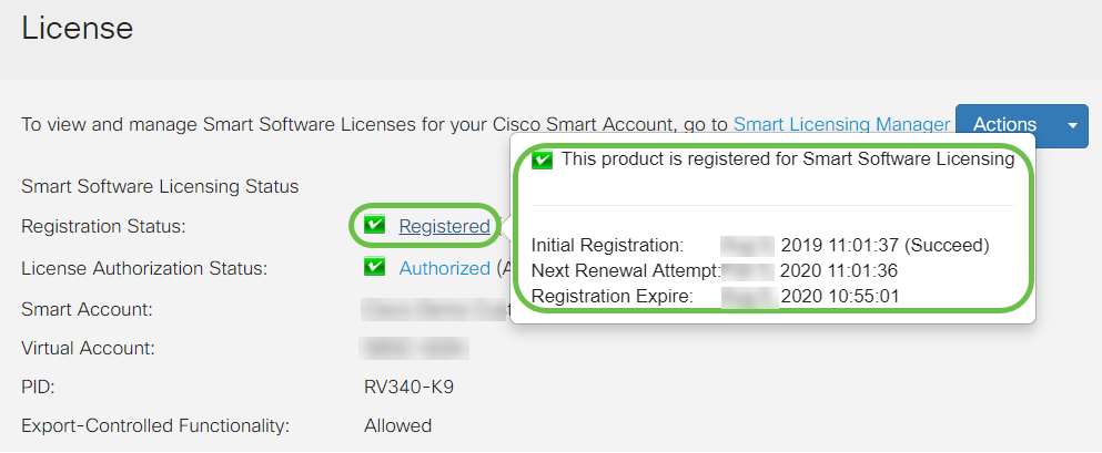
- Initial Registration — This area indicates the date and time the license was registered.
- Next Renewal Attempt — This area indicates the date and time the router will attempt to renew the license.
- Registration Expire — This area indicates the date and time the registration expires.
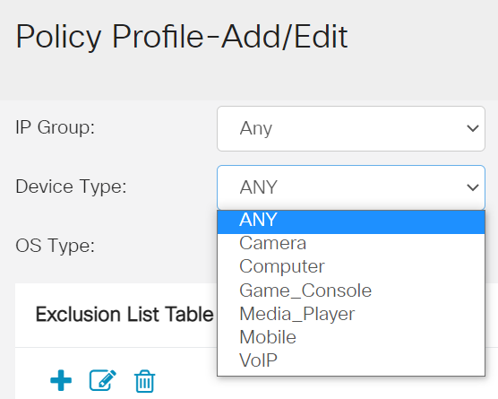
- ANY — Choose this to apply the policy to any device.
- Camera — Choose this to apply the policy to cameras (such as IP security cameras).
- Computer — Choose this to apply the policy to computers.
- Game_Console — Choose this to apply the policy to Gaming Consoles.
- Media_Player — Choose this to apply the policy to Media Players.
- Mobile — Choose this to apply the policy to mobile devices.
- VoIP — Choose this to apply the policy to Voice over Internet Protocol devices.
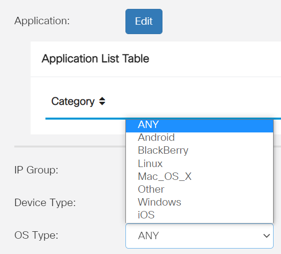
- ANY — Applies the policy to any type of OS. This is the default.
- Android — Applies the policy to Android OS only.
- BlackBerry — Applies the policy to Blackberry OS only.
- Linux — Applies the policy to Linux OS only.
- Mac_OS_X — Applies the policy to Mac OS only.
- Other — Applies the policy to an OS that is not listed.
- Windows — Applies the policy to the Windows OS.
- iOS — Applies the policy to iOS OS only.
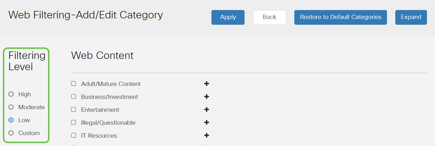
- Low — This is the default option. Security is enabled with this option.
- Moderate — Adult/Mature Content, Illegal/Questionable, and Security are enabled with this option.
- High — Adult/Mature Content, Business/Investment, Illegal/Questionable, IT Resources, and Security are enabled with this option.
- Custom — No defaults are set to allow user-defined filters.
- Follow up with the reseller to request they make the transfer.
- Reach out to us and we’ll get in touch with the reseller.
- Add API Key – Initiates the creation of a new key for use with the Umbrella API.
- Additional Info – Slides down/up with an explainer for this screen.
- Token Well – Contains all keys and tokens created by this account. (Populates once a key has been created)
- Support Documents – Links to documentation on the Umbrella site pertaining to the topics in each section.
- Secure and persistent connectivity
- Persistent security and policy enforcement
- Deployable from the Adaptive Security Appliance (ASA) or from Enterprise Software Deployment Systems
- Customizable and translatable
- Easily configured
- Supports both Internet Protocol Security (IPsec) and Secure Sockets Layer (SSL)
- Supports Internet Key Exchange version 2.0 (IKEv2.0) protocol
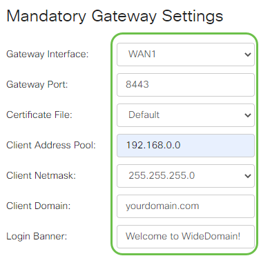
- Choose the Gateway Interface from the drop-down list. This will be the port that will be used for passing traffic through the SSL VPN Tunnels. The options include: WAN1, WAN2, USB1, USB2
- Enter the port number that is used for the SSL VPN gateway in the Gateway Port field ranging from 1 to 65535.
- Choose the Certificate File from the drop-down list. This certificate authenticates users who attempt to access the network resource through the SSL VPN tunnels. The drop-down list contains a default certificate and the certificates that are imported.
- Enter the IP address of the client address pool in the Client Address Pool field. This pool will be the range of IP addresses that will be allocated to remote VPN clients.
- Choose the Client Netmask from the drop-down list.
- Enter the client domain name in the Client Domain field. This will be the domain name that should be pushed to SSL VPN clients.
- Enter the text that would appear as a login banner in the Login Banner field. This will be the banner that will be displayed each time a client logs in.
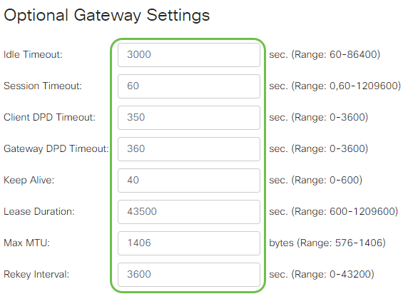
- Enter a value in seconds for the Idle Timeout ranging from 60 to 86400. This will be the time duration that the SSL VPN session can remain idle.
- Enter a value in seconds in the Session Timeout field. This is the time it takes for the Transmission Control Protocol (TCP) or User Datagram Protocol (UDP) session to time out after the specified idle time. The range is from 60 to 1209600.
- Enter a value in seconds in the ClientDPD Timeout field ranging from 0 to 3600. This value specifies the periodic sending of HELLO/ACK messages to check the status of the VPN tunnel. This feature must be enabled on both ends of the VPN tunnel.
- Enter a value in seconds in the GatewayDPD Timeout field ranging from 0 to 3600. This value specifies the periodic sending of HELLO/ACK messages to check the status of the VPN tunnel. This feature must be enabled on both ends of the VPN tunnel.
- Enter a value in seconds in the Keep Alive field ranging from 0 to 600. This feature ensures that your router is always connected to the Internet. It will attempt to re-establish the VPN connection if it is dropped.
- Enter a value in seconds for the duration of the tunnel to be connected in the Lease Duration field. The range is from 600 to 1209600.
- Enter the packet size in bytes that can be sent over the network. The range is from 576 to 1406.
- Enter the relay interval time in the Rekey Interval field. The Rekey feature allows the SSL keys to renegotiate after the session has been established. The range is from 0 to 43200.
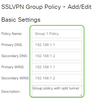
- Enter your preferred policy name in the Policy Name field.
- Enter the IP address of the Primary DNS in the field provided. By default, this IP address is already supplied.
- (Optional) Enter the IP address of the Secondary DNS in the field provided. This will serve as a backup in case the primary DNS failed.
- (Optional) Enter the IP address of the primary WINS in the field provided.
- (Optional) Enter the IP address of the secondary WINS in the field provided.
- (Optional) Enter a description of the policy in the Description field.
- None - Allows the browser to use no proxy settings.
- Auto - Allows the browser to automatically detect the proxy settings.
- Bypass-local - Allows the browser to bypass the proxy settings that are configured on the remote user.
- Disabled - Disables the MSIE proxy settings.
- LS-AC-PLS-1Y-S1 — 1-year Cisco AnyConnect Plus client license
- LS-AC-PLS-3Y-S1 — 3-year Cisco AnyConnect Plus client license
- LS-AC-PLS-5Y-S1 — 5-year Cisco AnyConnect Plus client license
- LS-AC-PLS-P-25-S — 25 pack Cisco AnyConnect Plus perpetual client license
- LS-AC-PLS-P-50-S — 50 pack Cisco AnyConnect Plus perpetual client license
- Windows: AnyConnect on a Windows Computer
- Mac: Install AnyConnect on Mac.
- Ubuntu Desktop: Installing and Using AnyConnect on Ubuntu Desktop
- If you have problems, you can go to Gather Information for Basic Troubleshooting on Cisco AnyConnect Secure Mobility Client Errors.
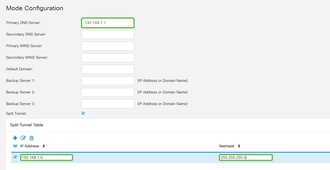
- Primary DNS Server: If you have an internal DNS Server or want to use an external DNS Server, you can enter it here. Otherwise, the default is set to the RV345P LAN IP address. We will use the default in our example.
- Split Tunnel: Check to enable Split Tunneling. This is used to specify which traffic will go over the VPN tunnel. We will use Split Tunnel in our example.
- Split Tunnel Table: Enter the networks the VPN client should have access to over the VPN. This example uses the RV345P LAN network.
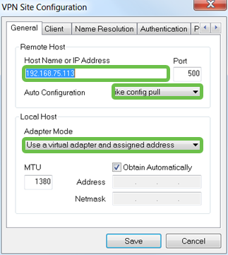
- Hostname or IP Address: Use the WAN IP address (or hostname of the RV345P)
- Auto Configuration: Select ike config pull
- Adapter Mode: Select Use a Virtual adapter and assigned address
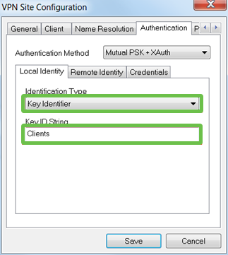
- Identification Type: Select Key Identifier
- Key ID String: Enter the Group Name that was configured on the RV345P
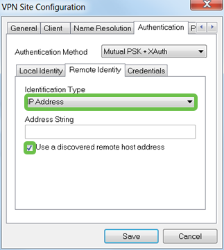
- Identification Type: IP Address
- Address String: <blank>
- Use a discovered remote host address box: Checked
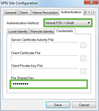
- Authentication Method: Select Mutual PSK + XAuth
- Pre-Shared Key: Enter the Pre-shared Key configured in the RV345P Client Profile
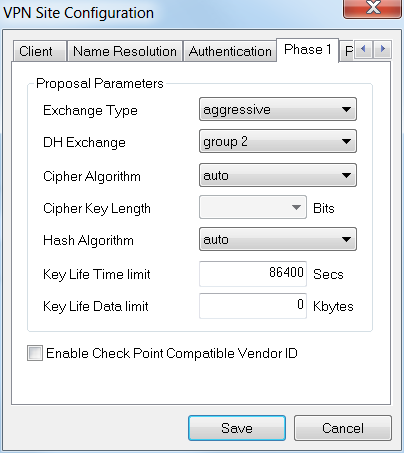
- Exchange Type: Aggressive
- DH Exchange: group 2
- Cipher Algorithm: Auto
- Hash Algorithm: Auto
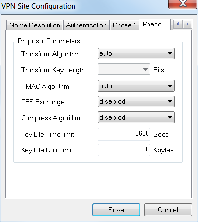
- Transform Algorithm: Auto
- HMAC Algorithm: Auto
- PFS Exchange: Disabled
- Compress Algorithm: Disabled
- Policy Generation Level: Auto
- Maintain Persistent Security Associations: Checked
- Obtain Topology Automatically or Tunnel All: Checked
- Use TheGreenBow VPN Client to Connect with RV34x Series Router
- Configure a Teleworker VPN Client on the RV34x Series Router
- Configure a Point-to-Point Tunneling Protocol (PPTP) Server on the Rv34x Series Router
- Configure an Internet Protocol Security (IPsec) Profile on an RV34x Series Router
- Configure L2TP WAN Settings on the RV34x Router
- Configuring Site-to-Site VPN on the RV34x
- Lease Time – Enter a time value of 5 to 43,200 minutes. The default is 1440 minutes (equal to 24 hours).
- Range Start and Range End – Enter the range start and end of IP addresses that can be assigned dynamically.
- DNS Server – Select to use the DNS server as a proxy, or from ISP from the drop-down list.
- WINS Server – Enter the WINS server name.
- DHCP Options:
- Option 66 – Enter the IP address of the TFTP server.
- Option 150 – Enter the IP address of a list of TFTP servers.
- Option 67 – Enter the configuration filename.
- Relay – Enter the remote DHCP server IPv4 address to configure the DHCP relay agent. This is a more advanced configuration.
- Access Port - Assigned one VLAN. Untagged frames are passed.
- Trunk Port - Can carry more than one VLAN. 802.1q. trunking allows for a native VLAN to be Untagged. VLANs that you don’t want on the trunk should be Excluded.
- Considered an Access port.
- The VLAN that is assigned to this port should be labeled Untagged.
- All other VLANs should be labeled Excluded for that port.
- Considered a Trunk Port.
- One of the VLANs can be labeled Untagged.
- The rest of the VLANs that are part of the Trunk Port should be labeled Tagged.
- The VLANs that are not part of the Trunk Port should be labeled Excluded for that port.
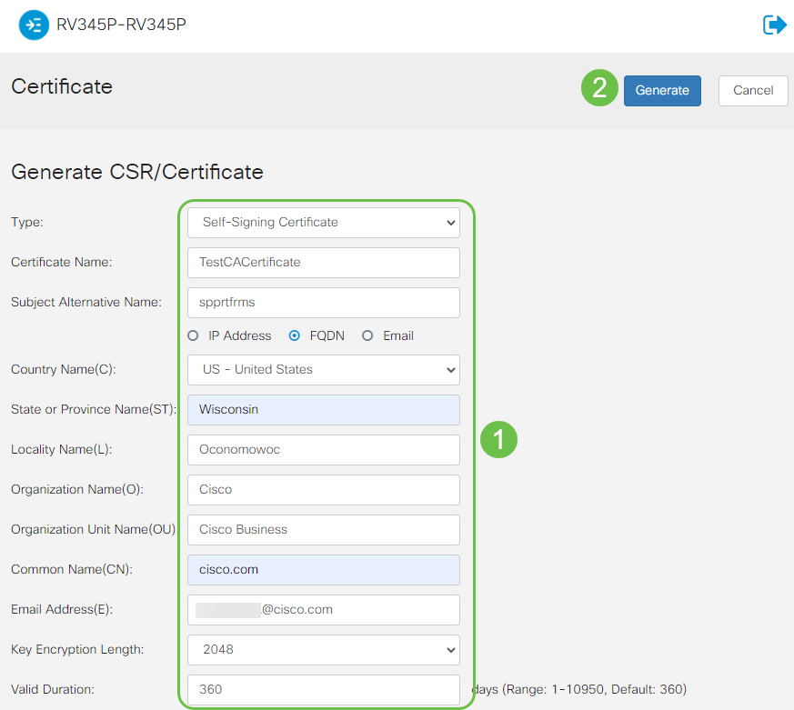
- Choose the appropriate certificate type
- Self-Signing Certificate — This is a Secure Socket Layer (SSL) certificate which is signed by its own creator. This certificate is less trusted, as it cannot be cancelled if the private key is compromised somehow by an attacker.
- Certified Signing Request — This is a Public Key Infrastructure (PKI) which is sent to the certificate authority to apply for a digital identity certificate. It is more secure than self-signed as the private key is kept secret.
- Enter a name for your certificate in the Certificate Name field to identify the request. This field cannot be blank nor contain spaces and special characters.
- (Optional) Under the Subject Alternative Name area, click a radio button. The options are:
- IP Address — Enter an Internet Protocol (IP) address
- FQDN — Enter a Fully Qualified Domain Name (FQDN)
- Email — Enter an email address
- In the Subject Alternative Name field, enter the FQDN.
- Choose a country name in which your organization is legally registered from the Country Name drop-down list.
- Enter a name or abbreviation of the state, province, region, or territory where your organization is located in the State or Province Name(ST) field.
- Enter a name of the locality or city in which your organization is registered or located in the Locality Name field.
- Enter a name under which your business is legally registered. If you are enrolling as a small business or sole proprietor, enter the name of the certificate requester in the Organization Name field. Special characters cannot be used.
- Enter a name in the Organization Unit Name field to differentiate between divisions within an organization.
- Enter a name in the Common Name field. This name must be the fully-qualified domain name of the website for which you use the certificate for.
- Enter the Email Address of person who wants to generate the certificate.
- From the Key Encryption Length drop-down list, choose a key length. The options are 512, 1024, and 2048. The greater the key length, the more secure the certificate.
- In the Valid Duration field, enter the number of days the certificate will be valid. The default is 360.
- Click Generate.
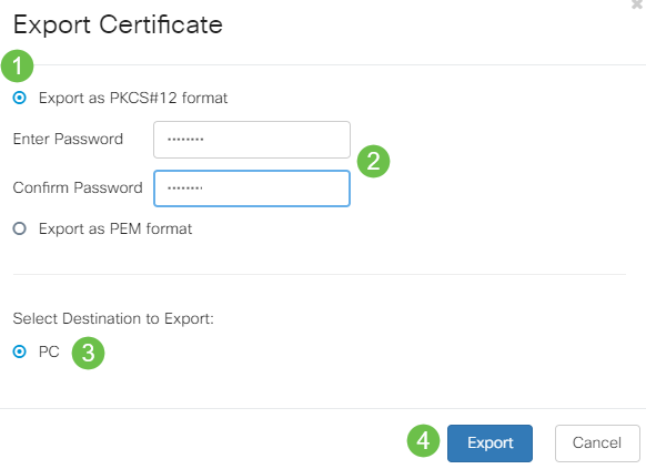
- Click a format to export the certificate. The options are:
- PKCS #12 — Public Key Cryptography Standards (PKCS) #12 is an exported certificate that comes in a .p12 extension. A password will be required in order to encrypt the file to protect it as it is exported, imported, and deleted.
- PEM — Privacy Enhanced Mail (PEM) is often used for web servers for their ability to be easily translated into readable data by using a simple text editor such as notepad.
- If you chose PEM, just click Export.
- Enter a password to secure the file to be exported in the Enter Password field.
- Re-enter the password in the Confirm Password field.
- In the Select Destination area, PC has been chosen and is the only option currently available.
- Click Export.
- Choose the type of certificate to import from the drop-down list. The options are:
- Local Certificate — A certificate generated on the router.
- CA Certificate — A certificate that is certified by a trusted third-party authority that has confirmed that the information contained in the certificate is accurate.
- PKCS #12 Encoded file — Public Key Cryptography Standards (PKCS) #12 is a format of storing a server certificate.
- Enter a name for the certificate in the Certificate Name field.
- If PKCS #12 was chosen, enter a password for the file in the Import Password field. Otherwise, skip to Step 3.
- Click a source to import the certificate. The options are:
- Import from PC
- Import from USB
- If the router does not detect a USB drive, the Import from USB option will be grayed out.
- If you chose Import From USB and your USB is not being recognized by the router, click Refresh.
- Click on the Choose File button and choose the appropriate file.
- Click Upload.
- Android version 5.0 or above
- iOS version 8.0 or above
- Create admin username
- Create admin password
- Confirm admin password by reentering it
- (Optional) Check the checkbox to Show Password.
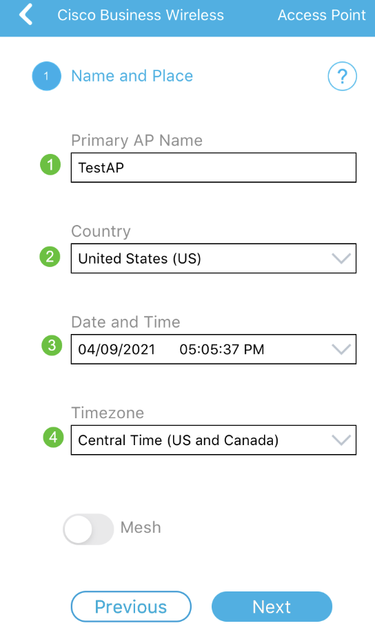
- Mobile Application AP Name for your wireless network.
- Country
- Date
- Time
- Timezone
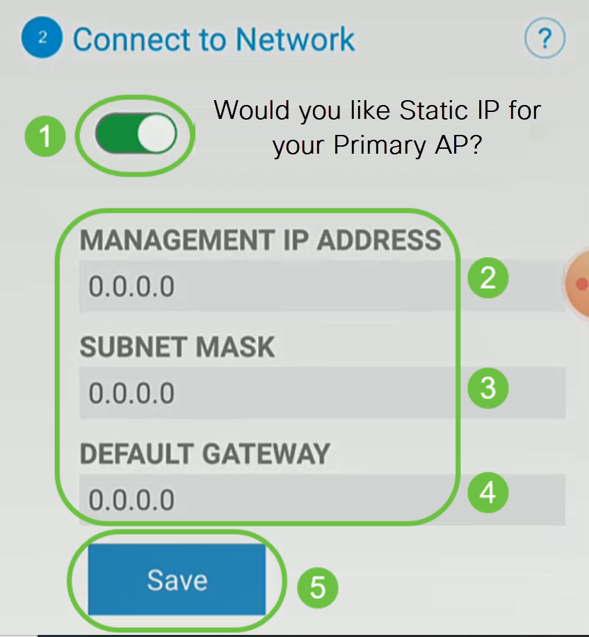
- Enter the Management IP Address
- Subnet Mask
- Default Gateway
- Network Name/SSID
- Security
- Passphrase
- Confirm passphrase
- (Optional) Check Show Passphrase
- Make sure the correct Service Set Identifier (SSID) is selected. This is the name that you created for the wireless network.
- Disconnect any VPN for either the mobile app or on a laptop. You might even be connected to a VPN that your mobile service provider uses that you might not even know. For example, an Android (Pixel 3) phone with Google Fi as a service provider there is a built-in VPN that auto-connects without notification. This would need to be disabled to find the Mobile Application AP.
- Log into the Mobile Application AP with https://<IP address of the Mobile Application AP>.
- Once you do the initial setup, be sure https:// is being used whether you are logging into ciscobusiness.cisco or by entering the IP address into your web browser. Depending on your settings, your computer may have auto-populated with http:// since that is what you used the very first time you logged in.
- To help with problems related to accessing the Web UI or browser issues during the use of the AP, in the web browser (Firefox in this case) click on the Open menu, go to Help > Troubleshooting Information and click on Refresh Firefox.
Topology
Introduction
All of your research has come together and you have purchased your Cisco equipment, how exciting! In this scenario, we are using an RV345P router. This router provides Power over Ethernet (PoE) which allows you to plug the CBW140AC into the router instead of a switch. The CBW140AC and the CBW142ACM mesh extenders will be used to create a wireless mesh network.
This advanced router also gives the option for additional features.
If you want to use these features, you will need to purchase a license. Routers and licenses are registered online, which will be covered in this guide.
If you are unfamiliar with some of the terms used in this document or want more details about Mesh Networking, check out the following articles:
Applicable Devices | Software Version
Prerequisites
Prepare the Router
Obtain a Cisco.com Account
Now that you own Cisco equipment, you need to get a Cisco.com Account, sometimes referred to as a Cisco Connection Online Identification (CCO ID). There is no charge for an account.
If you already have an account, you can jump to the next section of this article.
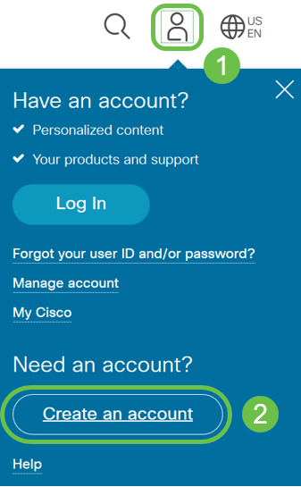
Step 1
Go to Cisco.com. Click the person icon and then Create an account.
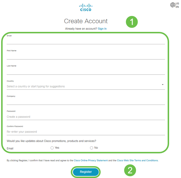
Step 2
Enter the required details to create the account and click Register. Follow the instructions to complete the registration process.
If you have any issues, click to jump to the Cisco.com Account Registration Help Page.
Configure the RV345P Router
A router is essential in a network because it routes packets. It enables a computer to communicate with other computers that are not on the same network or subnet. A router accesses a routing table to determine where packets should be sent. The routing table lists destination addresses. Static and dynamic configurations can both be listed on the routing table in order to get packets to their specific destination.
Your RV345P comes with default settings that are optimized for many small businesses. However, your network demands, or Internet Service Provider (ISP) might require you to modify a few of these settings. After you contact your ISP for the requirements, you can make changes using the Web User Interface (UI).
Are you ready? Let’s get to it!
RV345P Out of the Box
Step 1
Connect the Ethernet cable from one of the RV345P LAN (Ethernet) ports to the Ethernet port on the computer. You will need an adapter if your computer doesn’t have an Ethernet port. The terminal must be in the same wired subnetwork as the RV345P to perform the initial configuration.
Step 2
Be sure to use the power adapter that is supplied with the RV345P. Using a different power adapter could damage the RV345P or cause USB dongles to fail. The power switch is on by default.
Connect the power adapter to the 12VDC port of the RV345P, but don’t plug it into power yet.
Step 3
Make sure the modem is turned off.
Step 4
Use an Ethernet cable to connect your cable or DSL modem to the WAN port on the RV345P.
Step 5
Plug the other end of the RV345P adapter into an electrical outlet. This will power on the RV345P. Plug the modem back in so it can power up as well. The power light on the front panel is solid green when the power adapter is connected properly, and the RV345P is finished booting.
Set Up the Router
The prep work is done, now it’s time to get to some configurations! To launch the Web UI, follow these steps.
Step 1
If your computer is configured to become a Dynamic Host Configuration Protocol (DHCP) client, an IP address in the 192.168.1.x range is assigned to the PC. DHCP automates the process of assigning IP addresses, subnet masks, default gateways, and other settings to computers. Computers must be set to participate in the DHCP process to obtain an address. This is done by selecting to obtain an IP address automatically in the properties of TCP/IP on the computer.
Step 2
Open a web browser such as Safari, Internet Explorer, or Firefox. In the address bar, enter the default IP address of the RV345P, 192.168.1.1.

Step 3
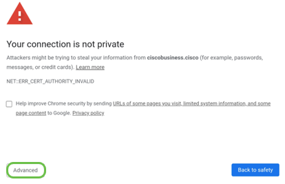
The browser might issue a warning that the website is untrusted. Continue to the website. If you are not connected, jump down to Troubleshooting the Internet Connection.
Step 4
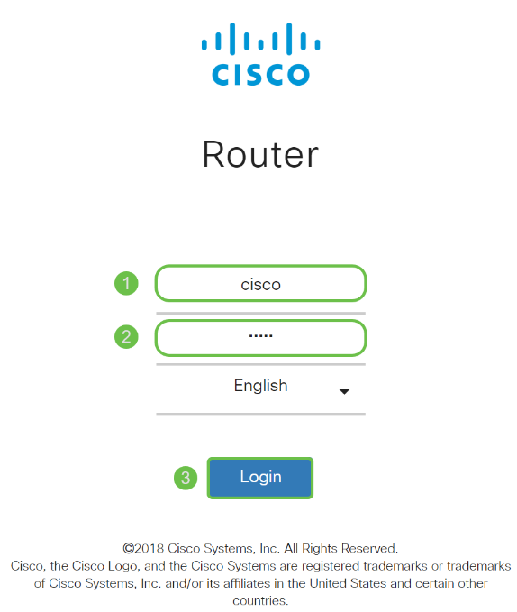
When the sign-in page appears, enter the default username cisco and the default password cisco.
Click Login.
For detailed information, click How to access the web-based setup page of Cisco RV340 series VPN routers.
Step 5
Click Login. The Getting Started page appears. If the navigation pane isn’t open, you can open it by clicking on the menu icon.

Now that you have confirmed the connection and logged in to the router, jump to the Initial Configuration section of this article.
Troubleshooting the Internet Connection
Dang it, if you are reading this you are probably having trouble connecting to the Internet or the Web UI. One of these solutions should help.
On your connected Windows OS, you can test your network connection by opening the command prompt. Enter ping 192.168.1.1 (the default IP address of the router). If the request times out, you are not able to communicate with the router.
If connectivity is not happening, you can check out this Troubleshooting article.
Some other things to try:
Initial Configuration
We recommend that you go through the Initial Setup Wizard steps listed in this section. You can change these settings at any time.
Step 1
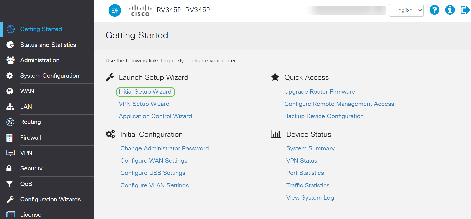
Click Initial Setup Wizard from the Getting Started Page.
Step 2
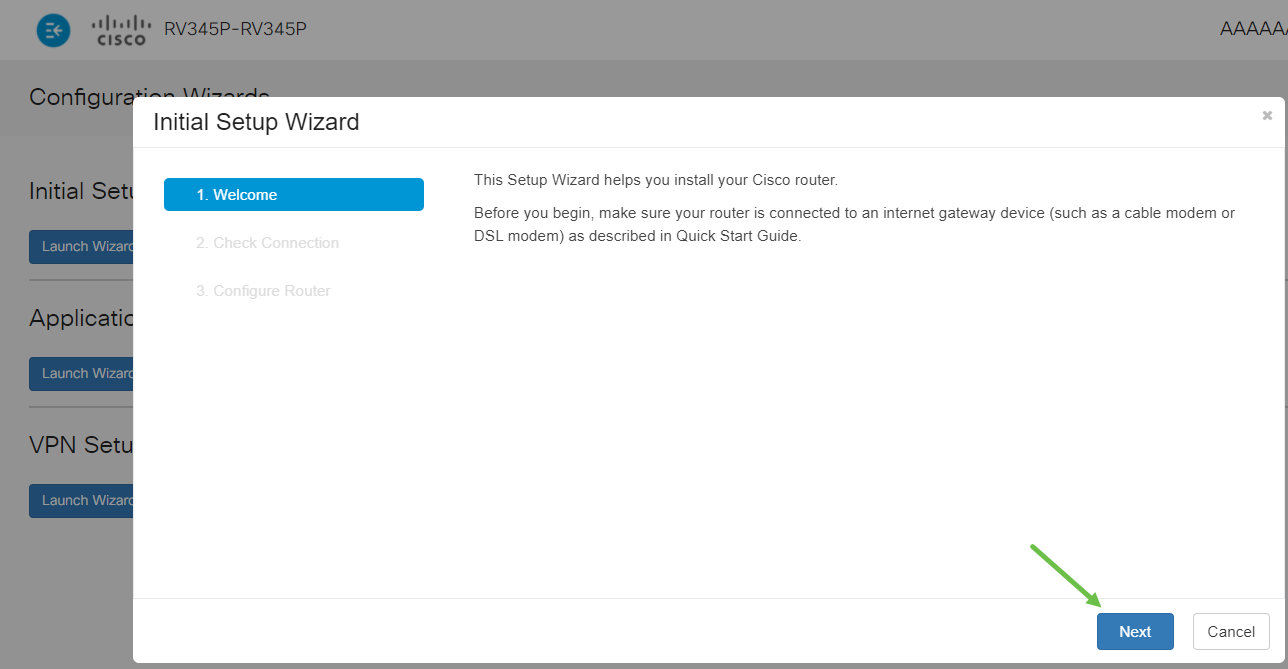
This step confirms the cables are connected. Since you confirmed this already, click Next.
Step 3
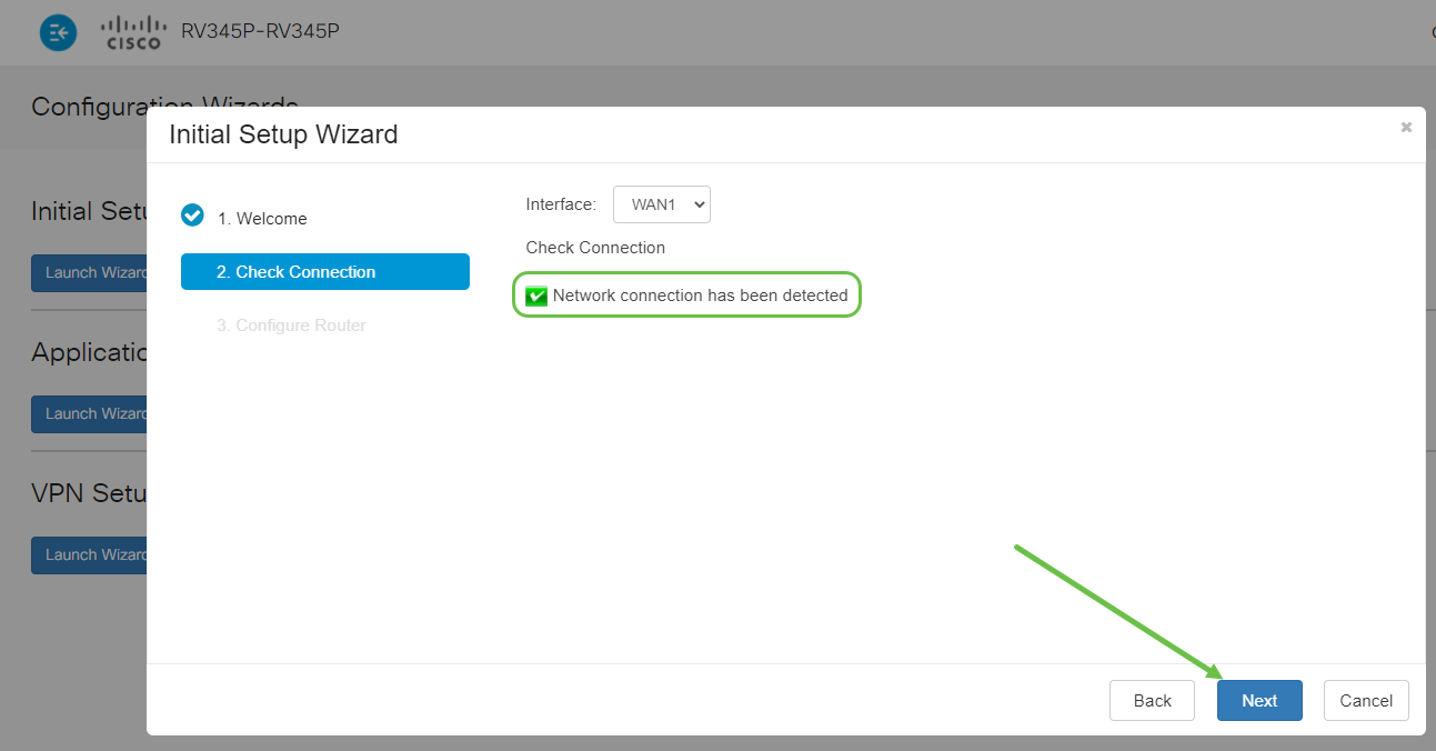
This step covers basic steps to make sure your router is connected. Since you have already confirmed this, click Next.
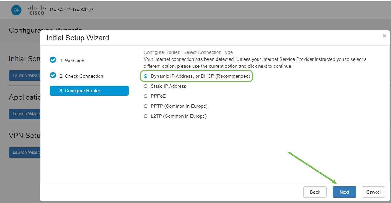
Step 4
The next screen displays your options for assigning IP addresses to your router. You need to select DHCP in this scenario. Click Next.
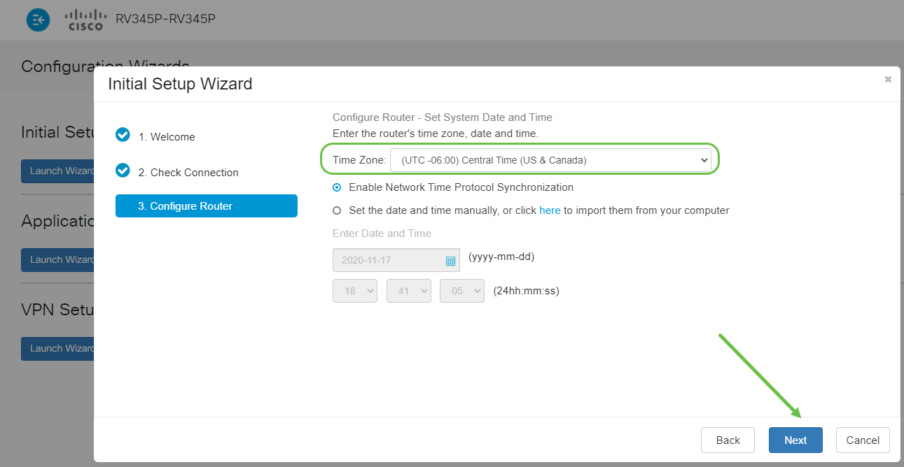
Step 5
You will be prompted to set your router time settings. This is important because it enables precision when reviewing logs or troubleshooting events. Select your Time Zone and then click Next.
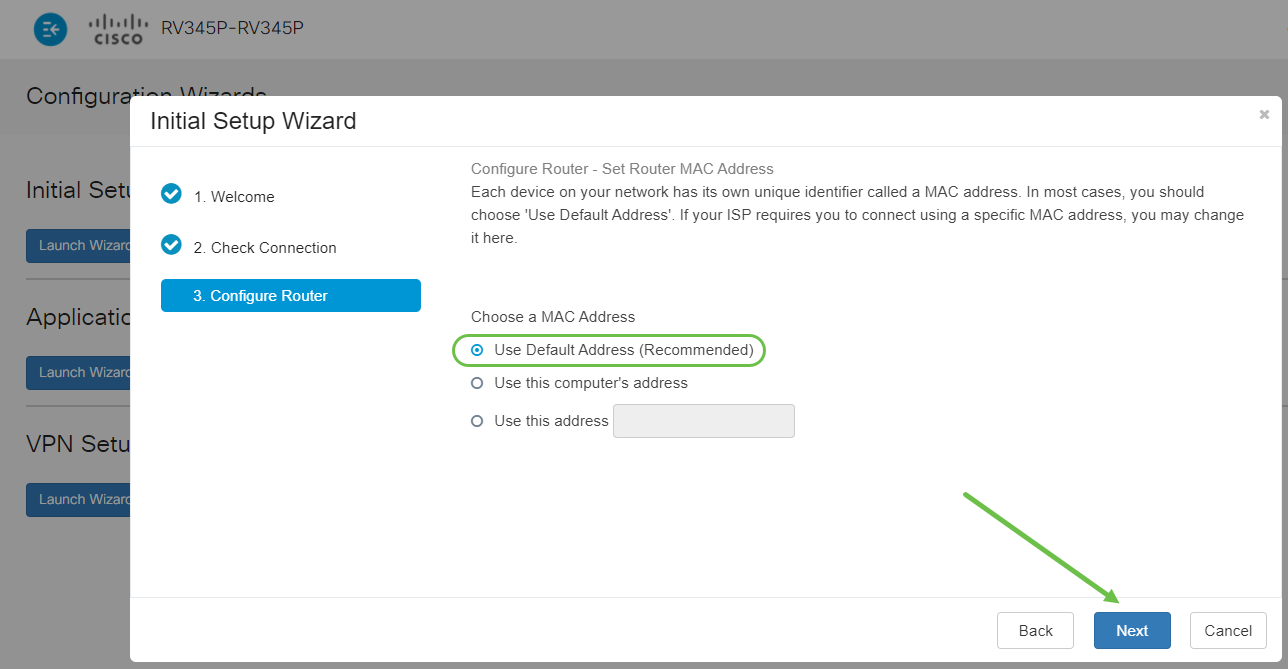
Step 6
You will select what MAC addresses to assign to devices. Most often, you will use the default address. Click Next.
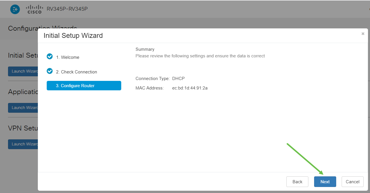
Step 7
The following page is a summary of the selected options. Review and click Next if satisfied.
Step 8
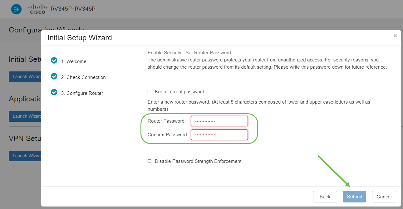
For the next step, you will select a password to use when logging into the router. The standard for passwords is to contain at least 8 characters (both upper and lower case) and include numbers. Enter a password that conforms with the strength requirements. Click Next. Take note of your password for future logins.
Step 9
Click the save icon.

If you want more information on these settings, you can read Configure DHCP WAN Settings on the RV34x Router.
Your RV345P has Power over Ethernet (PoE) enabled by default, but you have the ability to make some adjustments to them. If you need to customize the settings, check out Configure Power over Ethernet (PoE) Settings on the RV345P Router.
Edit an IP address If Necessary (Optional)
After completing the Initial Setup Wizard, you can set a static IP address on the router by editing the VLAN settings.
This process is only needed if your router IP address needs to be assigned a specific address in your existing network. If you don’t need to edit an IP address, you can move to the next section of this article.
Step 1
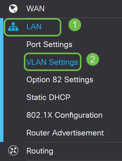
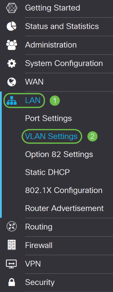
On the left-hand menu, click LAN > VLAN Settings.
Step 2
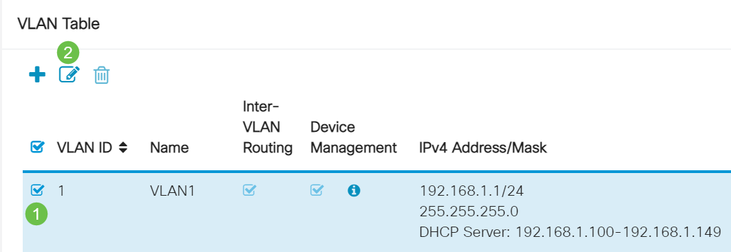
Select the VLAN that contains your routing device, then click the edit icon.
Step 3
Enter your desired static IP address and click Apply in the upper-right hand corner.

Step 4 (Optional)
If your router is not the DHCP server/device assigning IP addresses, you can use the DHCP Relay feature to direct DHCP requests to a specific IP address. The IP address is likely to be the router connected to the WAN/Internet.

Upgrade Firmware if Needed
This is an important step, don’t skip it!
Step 1
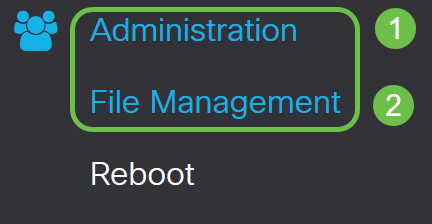
Choose Administration > File Management.
In the System Information area, the following sub-areas describe the following:
Step 2
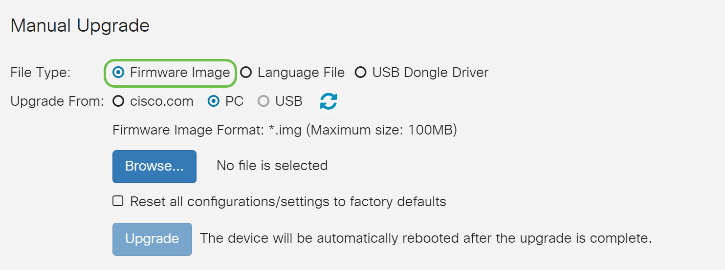
Under the Manual Upgrade section, click on the Firmware Image radio button for File Type.
Step 3
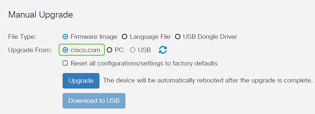
On the Manual Upgrade page, click on the radio button to select cisco.com. There are a few other options for this, but this is the easiest way to do an upgrade. This process installs the latest upgrade file directly from the Cisco Software Downloads webpage.
Step 4
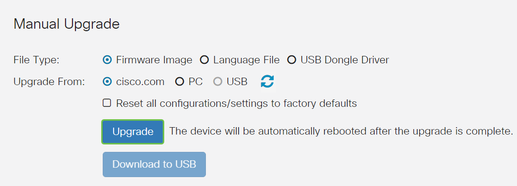
Click Upgrade.
Step 5
Click Yes in the confirmation window to continue.
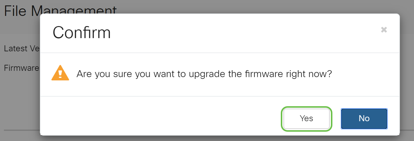

Once the upgrade has been completed, a notification window will pop-up to inform you that the router will be Restarting with a countdown of the estimated time for the process to finish. Following this, you will be logged out.

Step 6
Log back into the web-based utility to verify that the router firmware has been upgraded, scroll to System Information. The Current Firmware Version area should now display the upgraded firmware version.
Configure Automatic Updates on the RV345P Series Router
Since updates are so important and you are a busy person, it makes sense to configure automatic updates from here on out!
Step 1
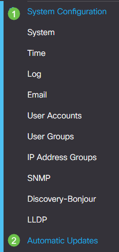
Log into the web-based utility and choose System Configuration > Automatic Updates.
Step 2
From the Check Every drop-down list, choose how often the router should check for updates.

Step 3
In the Notify via area, check the Email to checkbox to receive updates through email. The Admin GUI checkbox is enabled by default and cannot be disabled. A notification will appear in the web-based configuration once an update is available.
If you want to set up email server settings, click here to learn how.

Step 4
Enter an email address in the Email to address field.

Step 5
Under the Automatically Update area, check the Notify checkboxes of the kind of updates you want to be notified about. The options are:
Step 6
From the Automatic Update drop-down list, choose a time of the day you want the automatic update to be done. Some options may vary according to the type of update you have chosen. Security Signature is the only option to have an immediate update. It is recommended that you set a time when your office is closed so service isn’t interrupted at an inconvenient time.
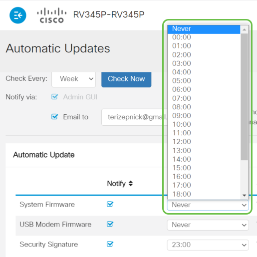
The status displays the currently running version of the firmware or security signature.
Step 7
Click Apply.

Step 8
To save the configuration permanently, go to the Copy/Save Configuration page or click the save icon at the upper portion of the page.

Awesome, your basic settings on your router are complete! Now you have some configuration options to explore.
Security Options
Of course, you want your network to be safe. There are some simple options, such as having a complex password, but if you want to take steps for an even more secure network check out this section on security.
RV Security License (Optional)
This RV Security License features protect your network from attacks from the Internet:
The RV Security License provides Web Filtering. Web Filtering is a feature that allows you to manage access to inappropriate websites. It can screen a client’s web access requests to determine whether to allow or deny that website.
Another Security option is Cisco Umbrella. Click here if you would like to jump to the Umbrella section instead.
If you don’t want either security license, click to jump to the VPN section of this document.
Introduction to Smart Accounts
To purchase the RV Security License, you need a Smart Account.
By authorizing the activation of this Smart Account, you agree that you are authorized to create accounts and manage product and service entitlements, license agreements, and user access to accounts on behalf of your organization. Cisco Partners may not authorize account creation on behalf of customers.
The creation of a new Smart Account is a one-time event and management from that point forward is provided through the tool.
Create a Smart Account
When you access your general Cisco account using your Cisco.com Account, or CCO ID (the one you created at the beginning of this document), you may be greeted by a message to create a Smart Account.
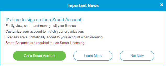
If you haven’t seen this pop-up, you can click to be taken to the Smart Account creation page. You may need to log in with your Cisco.com Account credentials.
For additional detail on the steps involved in requesting your Smart Account, click here.
Be sure to take note of your account name along with other registration details.
Quick Tip: If you are required to enter a domain and you do not have one, you can enter your email address in the form of name@domain.com. Common domains are gmail, yahoo, etc. depending on your company or provider.
Purchase RV Security License
You must purchase a license from your Cisco distributor or your Cisco partner. To locate a Cisco partner, click here.
The table below displays the part number for the license.
| Type | Product ID | Description |
|---|---|---|
| RV Security License | LS-RV34X-SEC-1YR= | RV Security: 1 year: Dynamic Web Filter, Application Visibility, Client Identification and Statistics, Gateway Antivirus, and Intrusion Prevention System IPS. |
The license key is not entered into your router directly but will be assigned to your Cisco Smart Account after you order the license. The amount of time it takes for the license to show up on your account depends on when the partner accepts the order and when the reseller links the licenses to your account, which is usually 24-48 hours.
Confirm License is in Smart Account
Navigate to your Smart License account page, then click Smart Software License page > Inventory > Licenses.
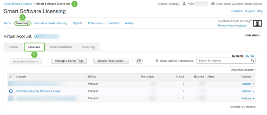
Configure the RV Security License on the RV345P Series Router
Step 1
Access Cisco Software and navigate to Smart Software Licensing.
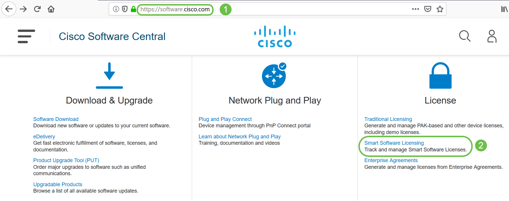
Step 2
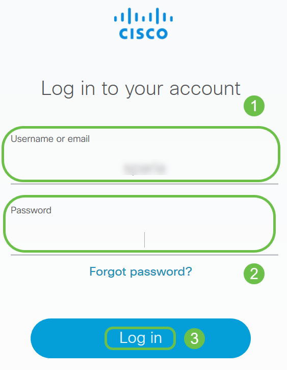
Enter your Username or email and Password to log into your Smart Account. Click Log in.
Step 3
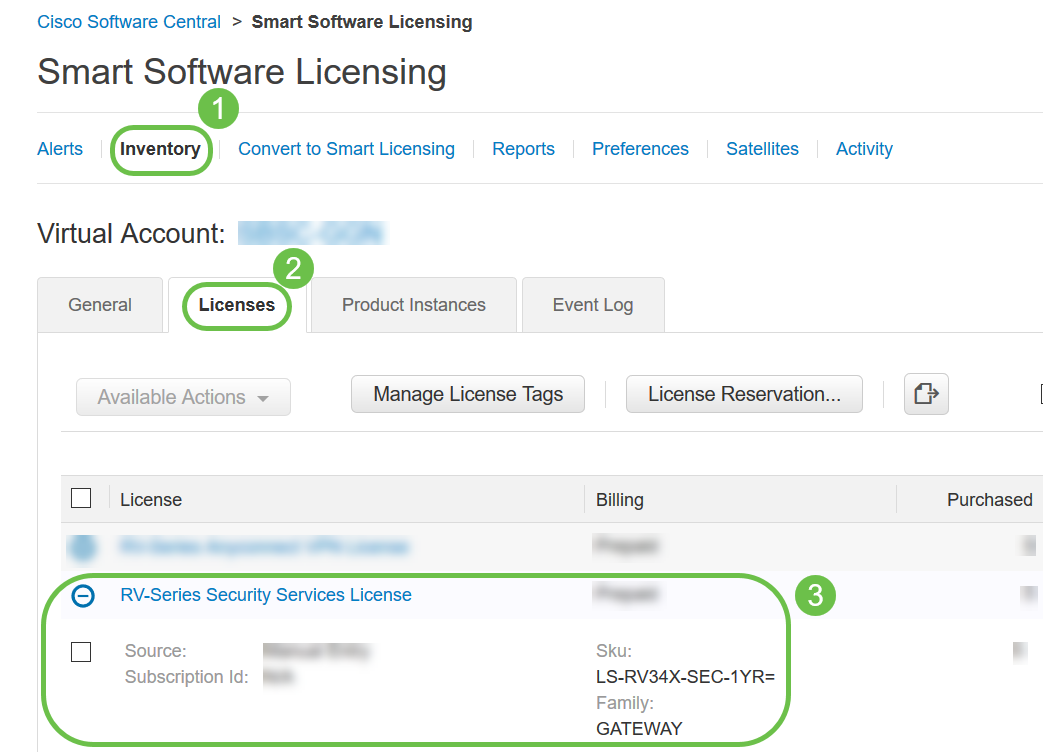
Navigate to Inventory > Licenses and verify that the RV-Series Security Services License is listed on your Smart Account. If you do not see the license listed, contact your Cisco partner.
Step 4
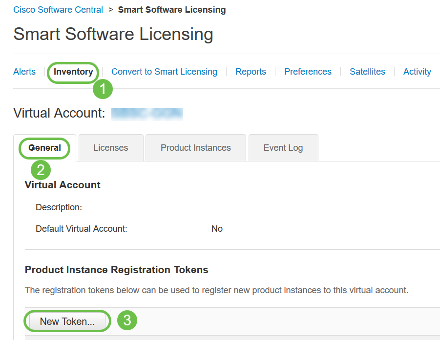
Navigate to Inventory > General. Under Product Instance Registration Tokens click on New Token.
Step 5
A Create Registration Token window will appear. The Virtual Account area displays the virtual account under which the registration token will be created. On the Create Registration Token page, complete the following:
You have now successfully generated a product instance registration token.

Step 6
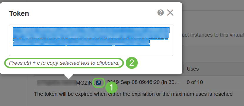
Click the arrow icon in the Token column, to copy the token to the clipboard press ctrl + c on your keyboard.
Step 7 (Optional)
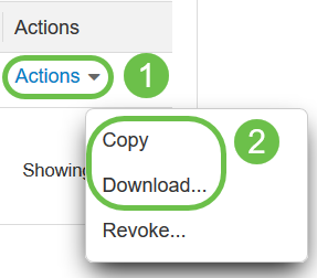
Click the Actions drop-down menu, choose Copy to copy the token to the clipboard or Download… to download a text file copy of the token from which you may copy.
Step 8
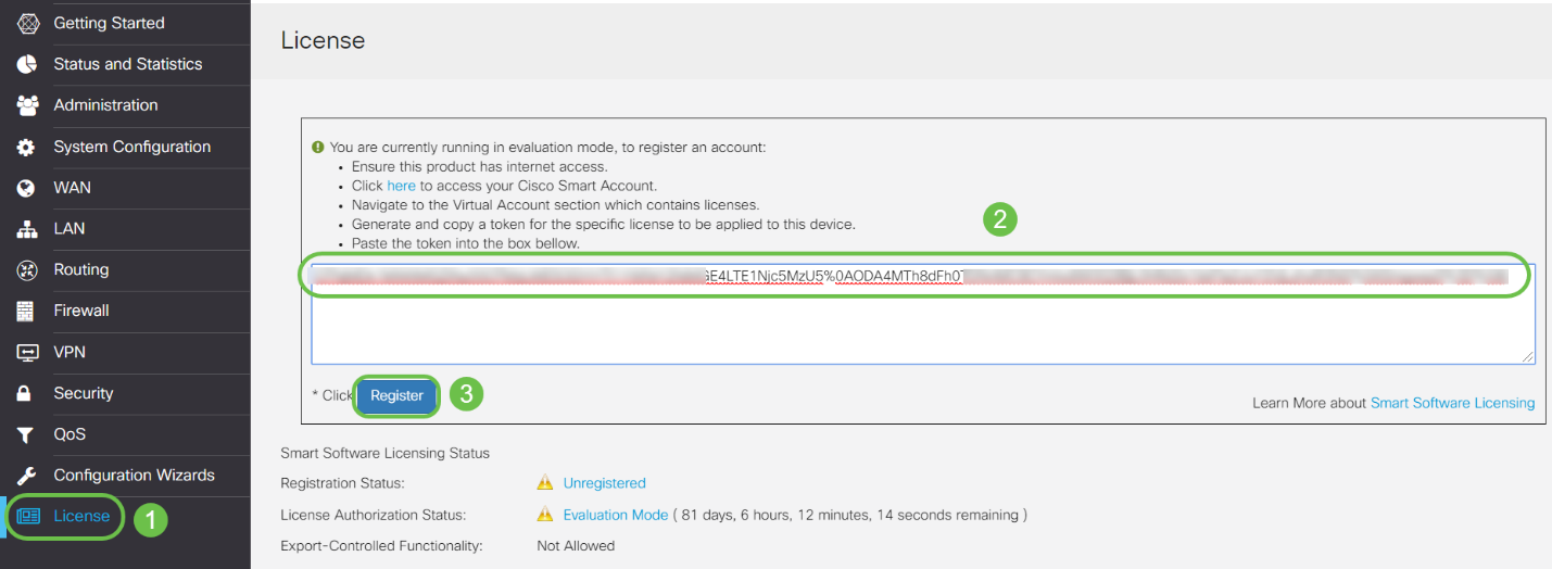
Navigate to License and verify the Registration Status is showing as Unregistered and License Authorization Status is showing as Evaluation Mode.

Step 9
Navigate to System Configuration > Time and verify the Current Date and Time and Time Zone are reflecting correctly as per your time zone.

Step 10
Navigate to License. Paste the copied token in step 6 on the text box under the License tab by selecting ctrl + v on your keyboard. Click Register.
The registration may take a few minutes. Do not leave the page as the router attempts to contact the license server.
Step 11
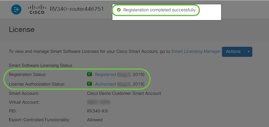
You should now have successfully registered and authorized your RV345P Series router with a Smart License. You will get a notification on the screen Registration completed successfully. Also, you will be able to see that the Registration Status is showing as Registered and License Authorization Status is showing as Authorized.
Step 12 (Optional)
To view more detail of the Registration Status of the license, hover your pointer over the Registered status. A dialog message appears with the following information:
Step 13
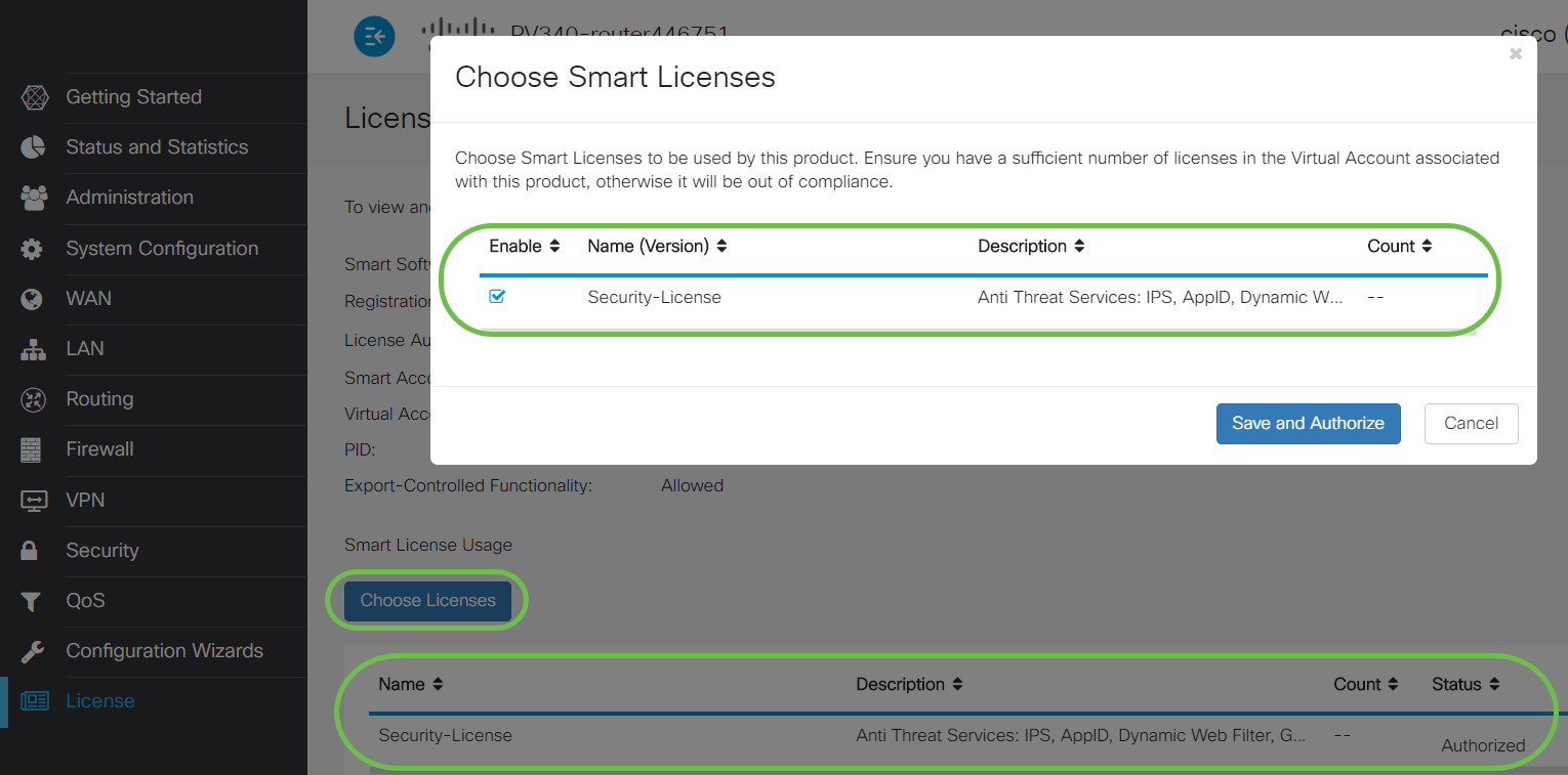
On the License page verify the Security-License status is showing Authorized. You may also click on the Choose License button to verify the Security-License is enabled.
Step 14 (Optional)
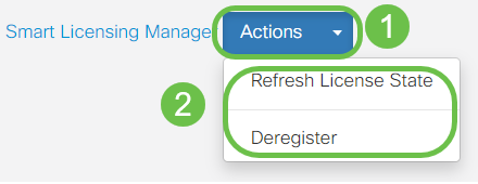
To Refresh License State or Deregister the license from the router, click on the Smart Licensing Manager Actions drop-down menu and select an action item.
Now that you have your license on the router, you need to complete the steps in the next section.
Web Filtering on the RV345P Router
You have 90 days after activation to use web filtering at no cost. After the free trial, if you want to continue using this feature, you need to purchase a license. Click to go back to that section.
Step 1
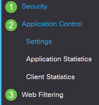
Log into the web-based utility and choose Security > Application Control > Web Filtering.
Step 2
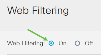
Select the On radio button.
Step 3
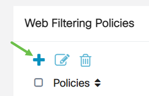
Click the add icon.
Step 4
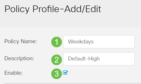
Enter a Policy Name, Description, and the Enable checkbox.
Step 5
Check the Web Reputation checkbox to enable filtering based on a web reputation index.

Step 6
From the Device Type drop-down list, select the source/destination of the packets to be filtered. Only one option can be chosen at a time. The options are:
Step 7
From the OS Type drop-down list, choose an Operating System (OS) to which the policy should be applicable. Only one option can be chosen at a time. The options are:
Step 8
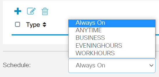
Scroll down to the Schedule section and select the option that best fits your needs.
Step 9
Click the edit icon.

Step 10
In the Filtering Level column, click a radio button to quickly define the filtering extent that would best fit the network policies. The options are High, Moderate, Low, and Custom. Click on any of the filtering levels below to know the specific pre-defined sub-categories filtered to each of their enabled Web Content Category. Pre-defined filters cannot be altered any further and are greyed out.
Step 11
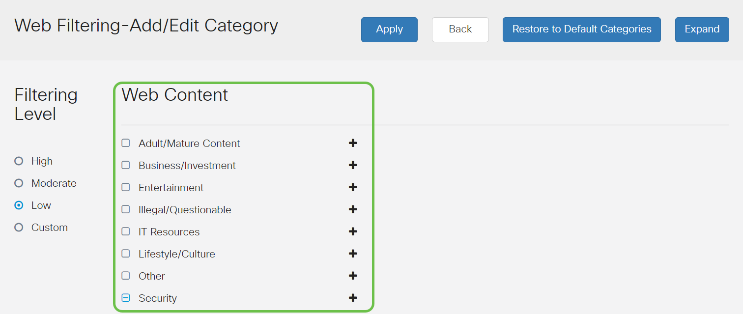
Enter the web content that you want to filter. Click on the plus icon if you want more detail on one section.
Step 12 (Optional)
To view all Web Content sub-categories and descriptions, you can click the Expand button.

Step 13 (Optional)
Click Collapse to collapse the sub-categories and descriptions.

Step 14 (Optional)
To return to the default categories, click Restore to Default Categories.

Step 15
Click Apply to save the configuration and to return to the Filter page to continue the setup.

Step 16 (Optional)
Other options include URL Lookup and the message that shows when a requested page has been blocked.

Step 17 (Optional)
Click Apply.

Step 18
To save the configuration permanently, go to the Copy/Save Configuration page or click the save icon at the upper portion of the page.

Step 19 (Optional)
To verify that a website or URL has been filtered or blocked, launch a web browser or open a new tab in your browser. Enter the domain name you have block listed or have filtered to be blocked or denied.
In this example, we used www.facebook.com.
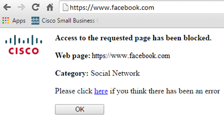
You should now have successfully configured web filtering on your RV345P Router. Since you are using the RV Security License for web filtering, you probably don’t need Umbrella. If you also want Umbrella, click here. If you have enough security, click to skip to the next section.
Troubleshooting
If you’ve purchased a license but it is not appearing in your virtual account, you have two options:
Ideally, you wouldn’t have to do either, but if you arrive at this crossroad we’re happy to help! To make the process as expedient as possible, you will need the credentials in the table above as well as those outlined below.
| Information Required | Locating the information |
|---|---|
| License Invoice | This should be emailed to you after completing the purchase of the licenses. |
| Cisco Sales Order number | You may need to go back to the reseller to get this. |
| Screenshot of your Smart Account license page | Taking a screenshot captures the contents of your screen for sharing with our team. If you’re unfamiliar with screenshots you can use the below methods. |
Screenshots
Once you have a token, or if you are troubleshooting, it is recommended that you take a screenshot to capture the contents of your screen.
Given the differences in the procedure required to capture a screenshot, see below for links specific to your operating system.
Umbrella RV Branch License (Optional)
Umbrella is a simple, yet very effective cloud security platform from Cisco.
Umbrella operates in the cloud and performs many security-related services. From emergent threat to post-event investigation. Umbrella discovers and prevents attacks across all ports and protocols.
Umbrella uses DNS as its main vector for defense. When users enter a URL in their browser bar and hit Enter, Umbrella participates in the transfer. That URL passes to Umbrella’s DNS resolver, and if a security warning associates with the domain, the request is blocked. This telemetry data transfers and is analyzed in microseconds, adding nearly no latency. Telemetry data uses logs and instruments tracking billions of DNS requests throughout the world. When this data is pervasive, correlating it across the globe enables rapid response to attacks as they begin. See Cisco’s privacy policy here for more information: full policy, summary version. Think of telemetry data as data derived from tools and logs.
Visit Cisco Umbrella to learn more and to create an account. If you run into any issues, check here for documentation, and here for Umbrella Support options.
Step 1
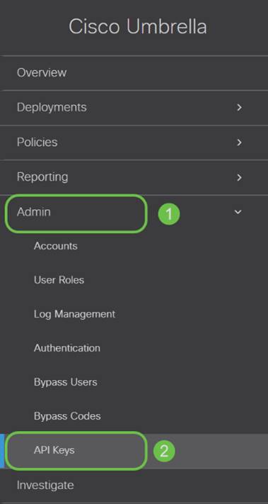
After logging into your Umbrella Account, from the Dashboard screen click on Admin > API Keys.
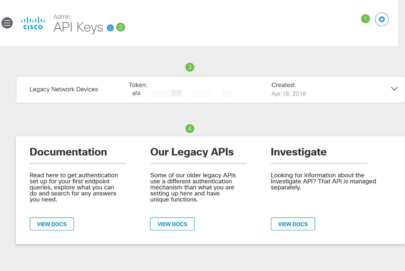
Anatomy of the API Keys Screen (with pre-existing API key)
Step 2
Click on the Add API Key button in the upper-right hand corner or click the Create API Key button. They both function the same.
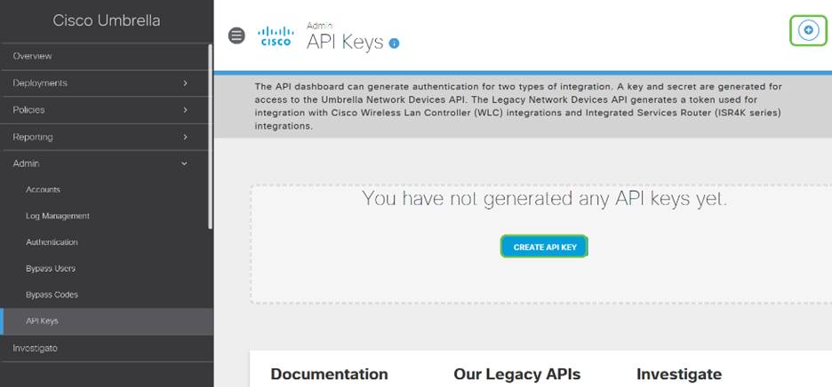
Step 3
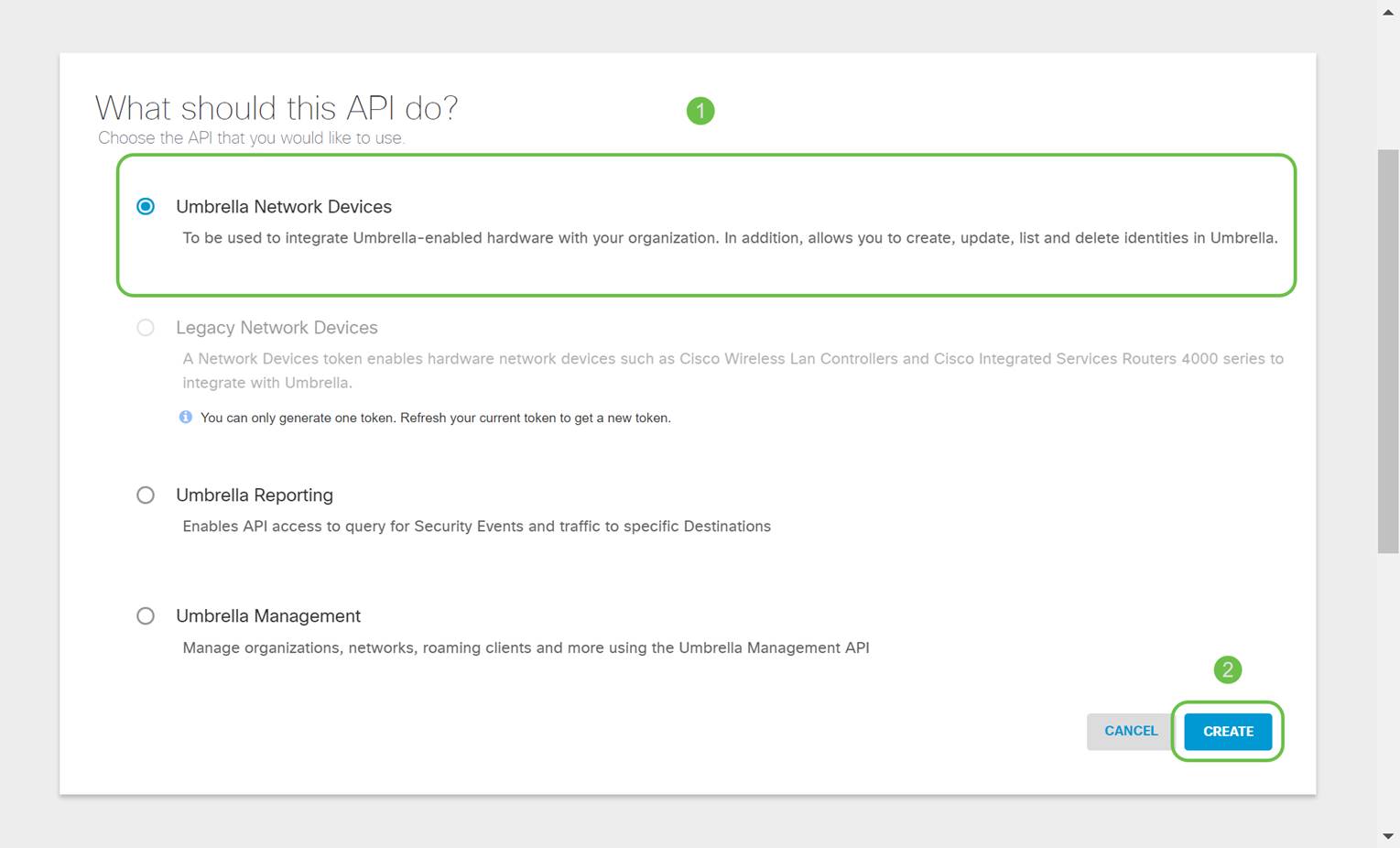
Select Umbrella Network Devices and then click the Create button.
Step 4
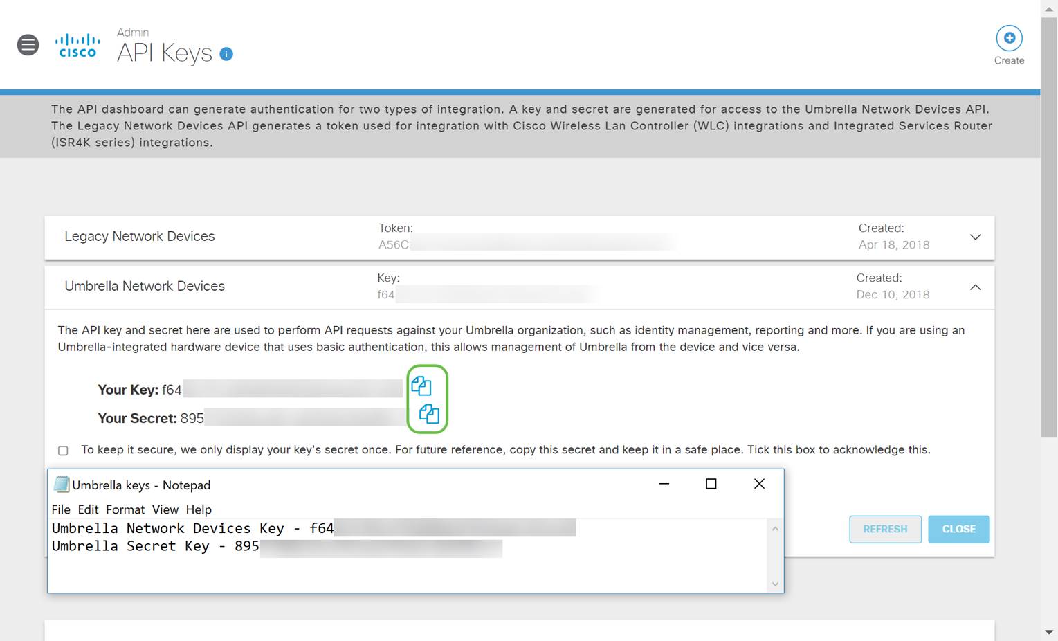
Open a text editor such as notepad then click the copy icon to the right of your API and API Secret Key, a pop-up notification will confirm the key is copied to your clipboard. One at a time, paste your secret and API key into the document, labeling them for future reference. In this case, its label is “Umbrella network devices key”. Then save the text file to a secure location that's easy to access later.
Step 5
After you’ve copied the key and secret key to a safe location, from the Umbrella API screen click the checkbox to confirm to complete acknowledgment of the temporary viewing of the secret key, then click the Close button.

Configuring Umbrella on your RV345P
Now that we’ve created API keys within Umbrella, you can take those keys and install them on your RV345P.
Step 1
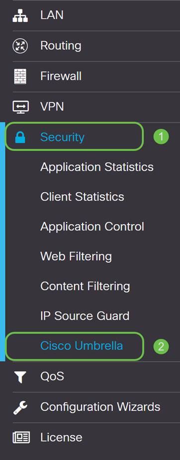
After logging into your RV345P router, click on Security > Umbrella in the sidebar menu.
Step 2
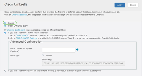
The Umbrella API screen has a range of options, begin enabling Umbrella by clicking the Enable checkbox.
Step 3 (Optional)
On by default, the box Block LAN DNS Queries is selected. This neat feature automatically creates access control lists on your router which will prevent DNS traffic from going out to the Internet. This feature forces all domain translation requests to be directed through the RV345P and is a good idea for most users.
Step 4
The next step plays out in two different ways. They both depend on the setup of your network. If you use a service like DynDNS or NoIP, you leave the default naming scheme of “Network”. You will need to log into those accounts to ensure Umbrella interfaces with those services as it provides protection. For our purposes we’re relying on “Network Device”, so we click on the bottom radio button.

Step 5
Click Getting Started.

Step 6
Enter the API Key and Secret Key to the text boxes.
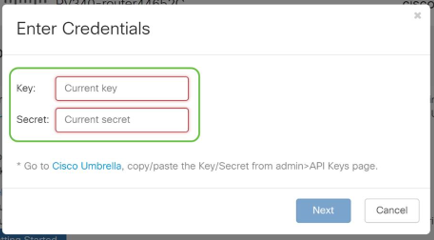
Step 7
After entering your API and Secret Key, click the Next button.
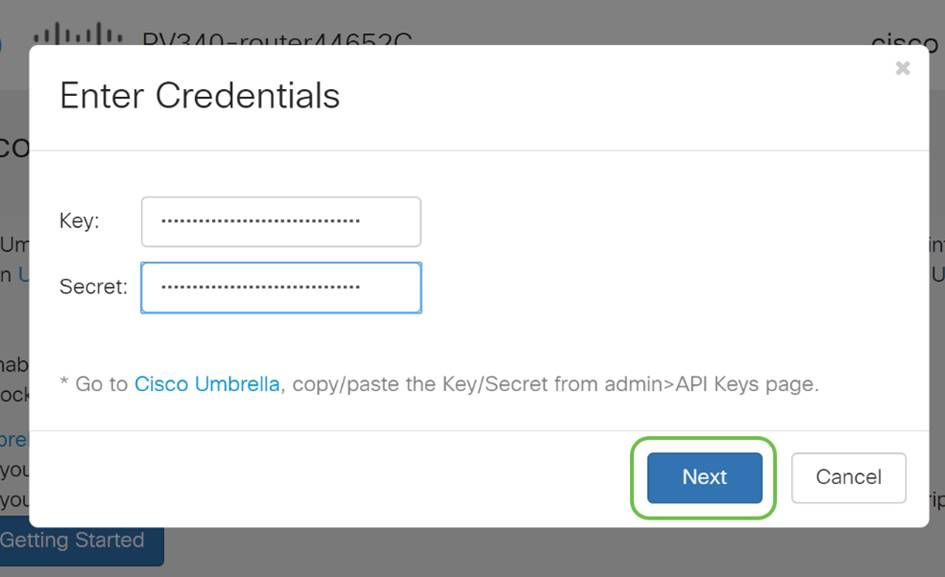
Step 8
In the next screen, select the organization you wish to associate with the router. Click Next.
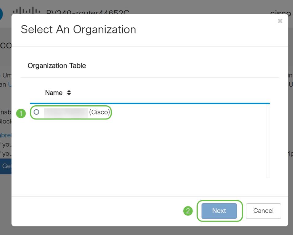
Step 9
Select the policy to apply to traffic routed by the RV345P. For most users, the default policy will provide enough coverage.
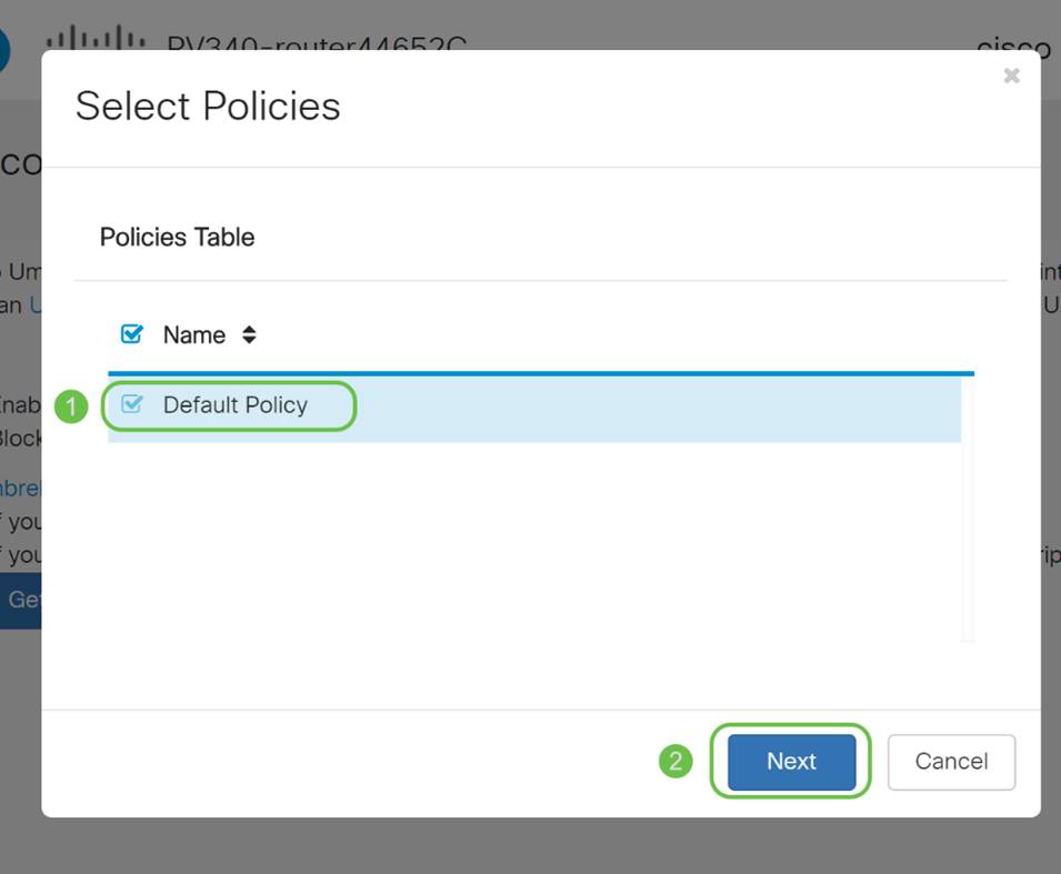
Step 10
Assign a name to the device so it may be designated in Umbrella reporting. In our setup, we have named it RV345P-Lab.
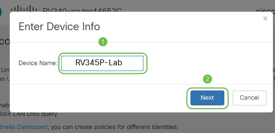
Step 11
The next screen will validate your chosen settings and provide an update when associated successfully. Click OK.
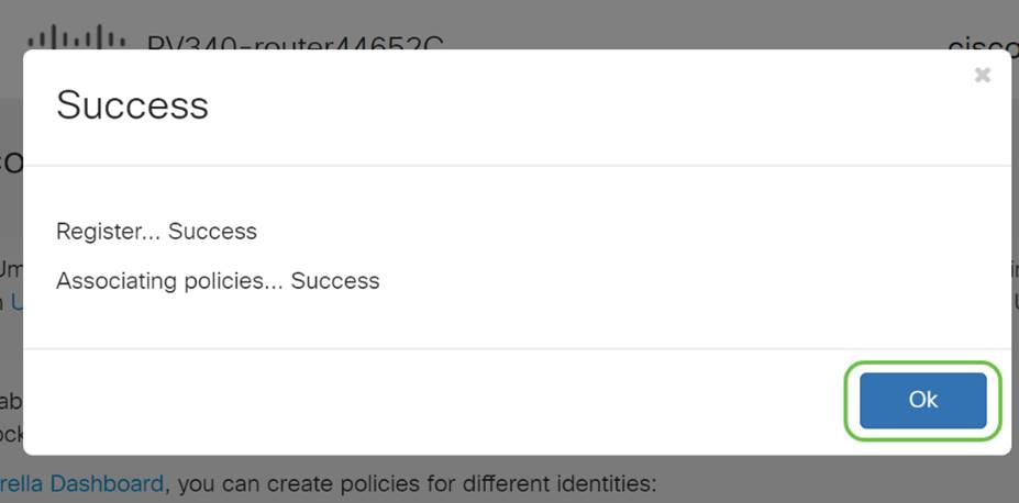
Confirmation
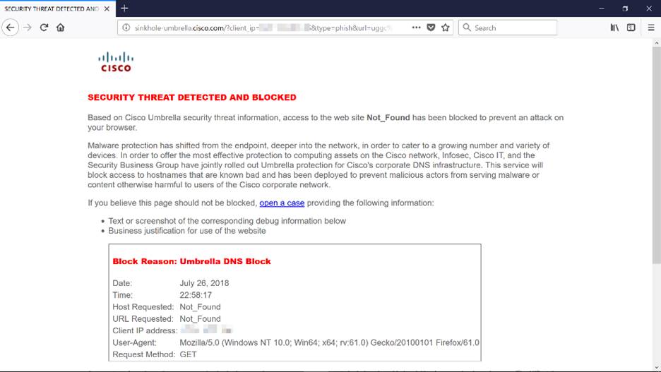
Congratulations, you are now protected by Cisco Umbrella. Or are you? Let’s be sure by double-checking with a live example, Cisco has created a website dedicated to determining this as quickly as the page loads. Click here or type https://InternetBadGuys.com into the browser bar.
If Umbrella is configured correctly, you will be greeted by a screen similar to this.
Other Security Options
Are you worried that someone would attempt unauthorized access to the network by unplugging an Ethernet cable from a network device and connecting to it? In this case, it is important to register a list of allowed hosts to directly connect to the router with their respective IP and MAC addresses. Instructions can be found in the article Configure IP Source Guard on the RV34x Series Router.
VPN Options
A Virtual Private Network (VPN) connection allows users to access, send, and receive data to and from a private network by means of going through a public or shared network such as the Internet but still ensuring a secure connection to an underlying network infrastructure to protect the private network and its resources.
A VPN tunnel establishes a private network that can send data securely using encryption and authentication. Corporate offices mostly use VPN connection since it is both useful and necessary to allow their employees to have access to their private network even if they are outside the office.
The VPN allows a remote host to act as if they were located on the same local network. The router supports up to 50 tunnels. A VPN connection can be set up between the router and an endpoint after the router has been configured for Internet connection. The VPN client is entirely dependent on the settings of the VPN router to be able to establish a connection.
If you are not sure which VPN best fits your needs, check out Cisco Business VPN Overview and Best Practices.
If you are not planning on setting up a VPN, you can click to jump to the next section.
VPN Passthrough
Generally, every router supports Network Address Translation (NAT) in order to conserve IP addresses when you want to support several clients with the same Internet connection. However, Point-to-Point Tunneling Protocol (PPTP) and Internet Protocol Security (IPsec) VPN do not support NAT. This is where the VPN Passthrough comes in. A VPN Passthrough is a feature that allows VPN traffic generated from VPN clients connected to this router to pass through this router and connect to a VPN endpoint. The VPN Passthrough allows PPTP and IPsec VPN only to pass through to the Internet, which is initiated from a VPN client, and then reach the remote VPN gateway. This feature is commonly found on home routers that support NAT.
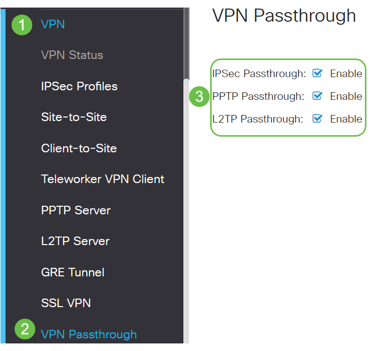
By default, IPsec, PPTP, and L2TP Passthrough are enabled. If you want to view or adjust these settings, select VPN > VPN Passthrough. View or adjust as needed.
AnyConnect VPN
There are several advantages to using Cisco AnyConnect:
Configure AnyConnect SSL VPN on the RV345P
Step 1
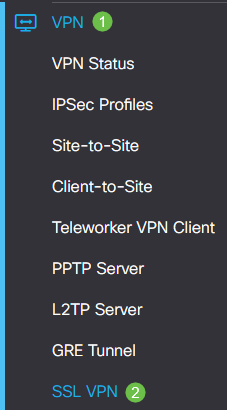
Access the router web-based utility and choose VPN > SSL VPN.
Step 2
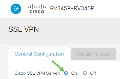
Click the On radio button to enable Cisco SSL VPN Server.
Mandatory Gateway Settings
Step 1
The following configuration settings are mandatory:
Make sure that the IP address range does not overlap with any of the IP addresses on the local network.
Step 2
Click Apply.

Optional Gateway Settings
Step 1
The following configuration settings are optional:
Step 2
Click Apply.

Configure Group Policies
Step 1
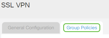
Click the Group Policies tab.
Step 2
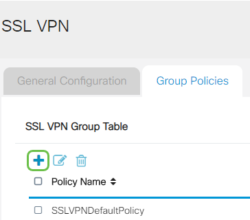
Click the add icon under the SSL VPN Group Table to add a group policy.
Step 3
Step 4 (Optional)
Click on a radio button to choose the IE Proxy Policy to enable Microsoft Internet Explorer (MSIE) proxy settings to establish VPN tunnel. The options are:

Step 5 (Optional)
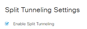
In the Split Tunneling Settings area, check the Enable Split Tunneling checkbox to allow Internet destined traffic to be sent unencrypted directly to the Internet. Full Tunneling sends all traffic to the end device where it is then routed to destination resources, eliminating the corporate network from the path for web access.
Step 6 (Optional)
Click on a radio button to choose whether to include or exclude traffic when applying the split tunneling.

Step 7
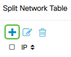
In the Split Network Table, click the add icon to add a split Network exception.
Step 8
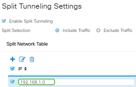
Enter the IP address of the network in the field provided.
Step 9
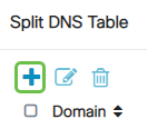
In the Split DNS Table, click the add icon to add a split DNS exception.
Step 10
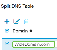
Enter the Domain name in the field provided and then click Apply.
The router comes with 2 AnyConnect server licenses by default. This means that once you have AnyConnect client licenses, you can establish 2 VPN tunnels simultaneously with any other RV340 series router.
In short, the RV345P router does not need a license, but all clients will need one. AnyConnect client licenses allow desktop and mobile clients to access the VPN network remotely.
This next section details how to get licenses for your clients.
AnyConnect Mobility Client
A VPN client is software that is installed and ran on a computer that wishes to connect to the remote network. This client software must be set up with the same configuration as that of the VPN server such as the IP address and authentication information. This authentication information includes the username and the pre-shared key that will be used to encrypt the data. Depending on the physical location of the networks to be connected, a VPN client can also be a hardware device. This usually happens if the VPN connection is used to connect two networks that are in separate locations.
The Cisco AnyConnect Secure Mobility Client is a software application for connecting to a VPN that works on various operating systems and hardware configurations. This software application makes it possible for remote resources of another network to become accessible as if the user is directly connected to his network, but in a secure way.
Once the router is registered and configured with AnyConnect, the client can install licenses on the router from your available pool of licenses that you purchase, which is detailed in the next section.
Purchase License
You must purchase a license from your Cisco distributor or your Cisco partner. When ordering a license, you must provide your Cisco Smart Account ID or Domain ID in the form of name@domain.com.
If you don’t have a Cisco distributor or partner, you can locate one here.
At the time of writing, the following Product SKUs can be used to purchase additional licenses in bundles of 25. Note that there are other options for the AnyConnect client licenses as outlined in the Cisco AnyConnect Ordering Guide, however, the Product ID listed would be the minimum requirement for full functionality.
Please note, the AnyConnect client license Product SKU listed first, provides licenses for a term of 1 year, and requires a minimum purchase of 25 licenses. Other product SKUs which are applicable to the RV340 series routers are also available with varying subscription levels, as follows:
Client Information
When your client sets up one of the following, you should send them these links:
Verify AnyConnect VPN Connectivity
Step 1
Click on the AnyConnect Secure Mobility Client icon.

Step 2
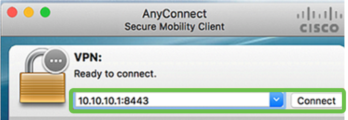
In the AnyConnect Secure Mobility Client window, enter the gateway IP address and the gateway port number separated by a colon (:), and then click Connect.
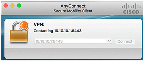
The software will now show that it is contacting the remote network.
Step 3
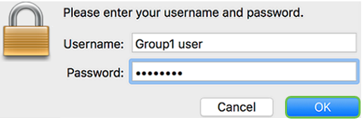
Enter your server username and password in the respective fields and then click OK.
Step 4
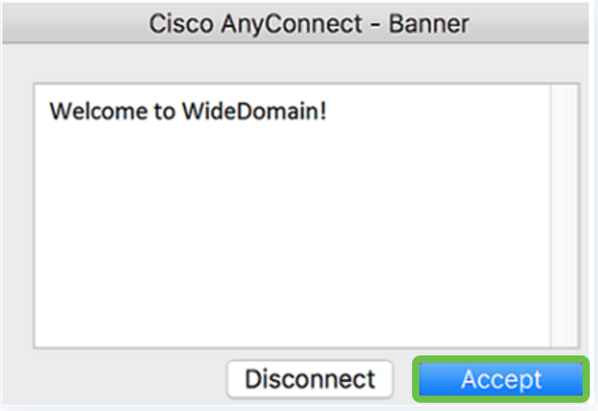
As soon as the connection is established, the Login Banner will appear. Click Accept.
The AnyConnect window should now indicate the successful VPN connection to the network.
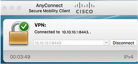
If you are now using AnyConnect VPN, you can skip past other VPN options and move to the next section.
Shrew Soft VPN
An IPsec VPN allows you to securely obtain remote resources by establishing an encrypted tunnel across the Internet. The RV34X series routers work as IPsec VPN servers and support the Shrew Soft VPN Client. This section will show you how to configure your router and the Shrew Soft Client to secure a connection to a VPN.
You can download the latest version of the Shrew Soft VPN client software here: https://www.shrew.net/download/vpn
Configure Shrew Soft on the RV345P Series Router
We will start by configuring the Client-to-Site VPN on the RV345P.
Step 1
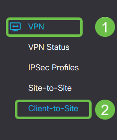
Navigate to VPN > Client-to-Site.
Step 2
Add a Client-to-Site VPN profile.

Step 3
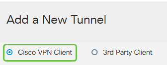
Select the Cisco VPN Client option.
Step 4
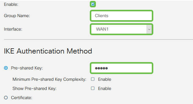
Check the Enable box to make the VPN Client Profile active. We will also configure the Group Name, select the WAN interface, and enter a Pre-shared Key.
Step 5
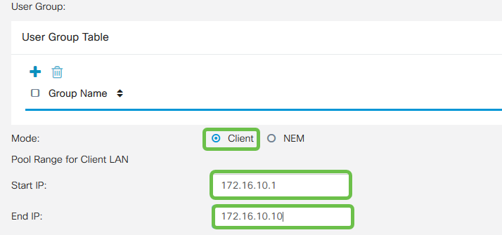
Leave the User Group Table blank for now. This is for the User Group on the router, but we have not configured it yet. Make sure the Mode is set to Client. Enter the Pool Range for Client LAN. We will use 172.16.10.1 through 172.16.10.10.
Step 6
Here is where we configure the Mode Configuration settings. Here are the settings we will use:
Step 7
After clicking Save, we can see the Profile in the IPsec Client-to-Site Groups list.

Step 8
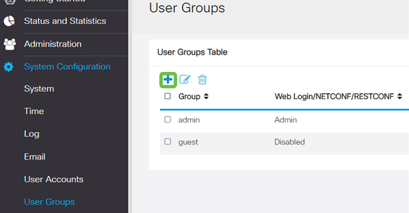
Configure a User Group to use for Authenticating VPN client users. Under System Configuration > User Groups, click on the plus icon to add a User Group.
Step 9
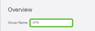
Enter a Group Name.
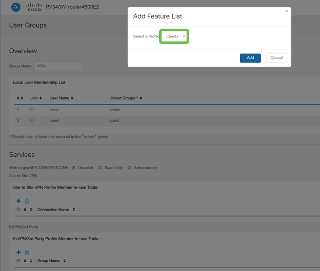
Step 10
Under Services > EzVPN/3rd Party, click Add to link this User Group to the Client-to-Site Profile that was configured earlier.
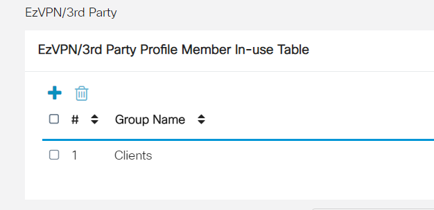
Step 11
You should now see the Client-to-Site Group Name in the list for EzVPN/3rd Party.
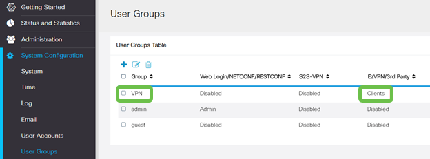
Step 12
After you Apply the User Group configuration, you will see it in the User Groups list and it will show the new User Group will be used with the Client-to-Site Profile you created earlier.
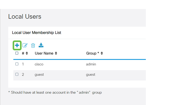
Step 13
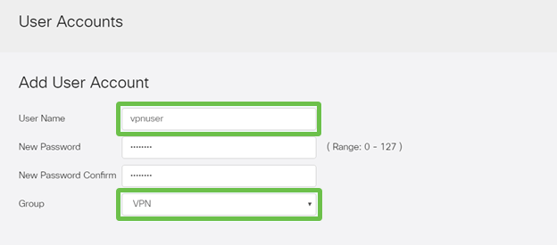
Configure a new User in System Configuration > User Accounts. Click on the plus icon to create a new user.
Step 14
Enter the new User Name along with the New Password. Verify that the Group is set to the new User Group you just configured. Click Apply when finished.
Step 15
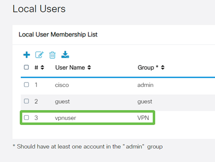
The new User will show up in the list of Local Users.
This completes the configuration on the RV345P Series Router. Next, you will configure the Shrew Soft VPN client.
Configure the Shrew Soft VPN client
Perform the following steps.
Step 1
Open the Shrew Soft VPN Access Manager and click Add to add a Profile. In the VPN Site Configuration window that appears, configure the General tab:
Step 2
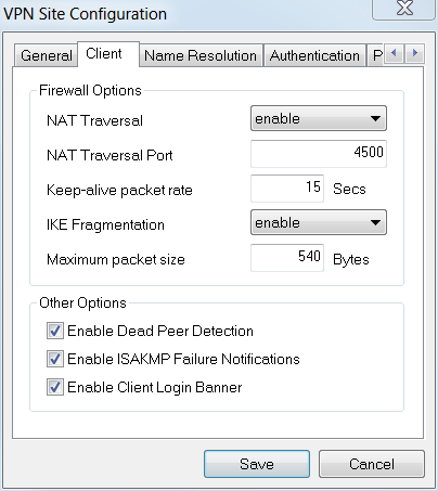
Configure the Client tab. In this example, we kept the default settings.
Step 3
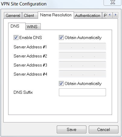
Under Name Resolution > DNS, check the Enable DNS box and leave the Obtain Automatically boxes checked.
Step 4
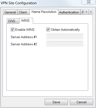
Under Name Resolution > WINS tab, check the Enable WINS box and leave the Obtain Automatically box checked.
Step 5
Click Authentication > Local Identity.
Step 6
Under Authentication > Remote Identity. In this example, we kept the default settings.
Step 7
Under Authentication > Credentials, configure the following:
Step 8
For the Phase 1 tab. In this example, the default settings were kept:
Step 9
In this example, the defaults for the Phase 2 tab were kept the same.
Step 10
For the Policy tab example, we used the following settings:
Since we configured Split-Tunneling on the RV345P, we don’t need to configure it here.
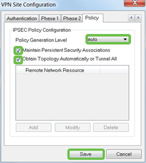
When finished, click Save.
Step 11
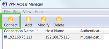
You are now ready to test the connection. In VPN Access Manager, highlight the connection profile and click on the Connect button.
Step 12
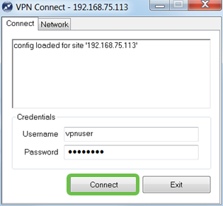
In the VPN Connect window that comes up, enter the Username and Password using the credentials for the User Account you created on the RV345P (step 13 & 14). When finished, click Connect.
Step 13
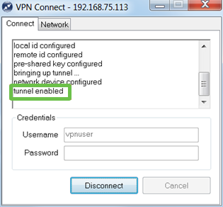
Verify the tunnel is connected. You should see tunnel enabled.
Other VPN Options
There are some other options for using a VPN. Click on the following links for more information:
Supplemental Configurations on the RV345P Router
Configure VLANs (Optional)
A Virtual Local Area Network (VLAN) allows you to logically segment a Local Area Network (LAN) into different broadcast domains. In scenarios where sensitive data may be broadcast on a network, VLANs can be created to enhance security by designating a broadcast to a specific VLAN. VLANs can also be used to enhance performance by reducing the need to send broadcasts and multicasts to unnecessary destinations. You can create a VLAN, but this has no effect until the VLAN is attached to at least one port, either manually or dynamically. Ports must always belong to one or more VLANs.
You may want to refer to VLAN Best Practices and Security Tips for additional guidance.
If you do not want to create VLANs, you can skip to the next section.
Step 1
Navigate to LAN > VLAN Settings.
Step 2
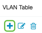
Click the add icon to create a new VLAN.
Step 3
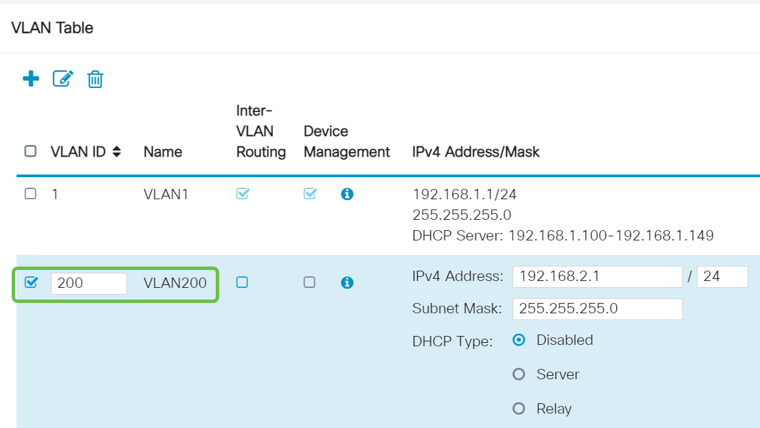
Enter the VLAN ID that you want to create and a Name for it. The VLAN ID range is from 1-4093.
Step 4
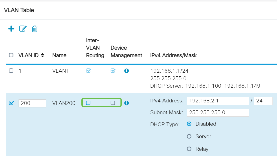
Uncheck the Enabled box for both Inter-VLAN Routing and Device Management if desired. Inter-VLAN routing is used to route packets from one VLAN to another VLAN.
In general, this is not recommended for guest networks as you will want to isolate guest users it leaves VLANs less secure. There are times when it may be necessary for VLANs to route between each other. If this is the case, check out Inter-VLAN Routing on an RV34x Router with Targeted ACL Restrictions to configure specific traffic that you allow between VLANs.
Device Management is the software that allows you to use your browser to log into the Web UI of the RV345P, from the VLAN, and manage the RV345P. This should also be disabled on Guest networks.
In this example, we did not enable either the Inter-VLAN Routing or Device Management to keep the VLAN more secure.
Step 5
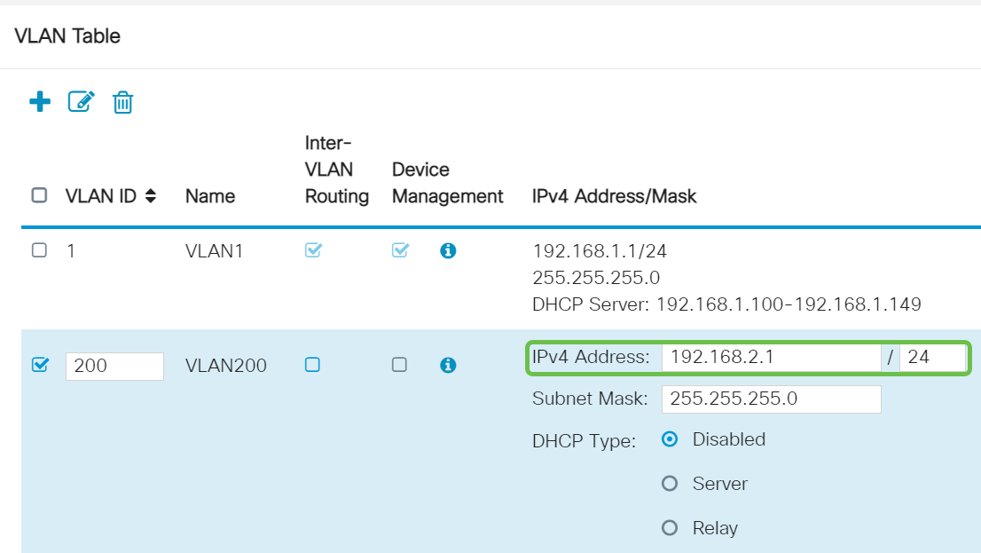
The private IPv4 address will auto-populate in the IP Address field. You can adjust this if you choose. In this example, the subnet has 192.168.2.100-192.168.2.149 IP addresses available for DHCP. 192.168.2.1-192.168.2.99, and 192.168.2.150-192.168.2.254 are available for static IP addresses.
Step 6
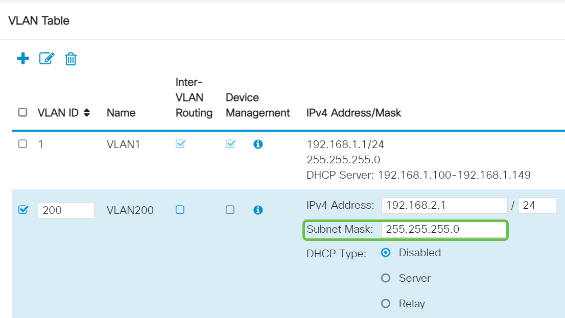
The subnet mask under Subnet Mask will auto-populate. If you make changes, this will automatically adjust the field.
For this demonstration, we will be leaving the Subnet Mask as 255.255.255.0 or /24.
Step 7
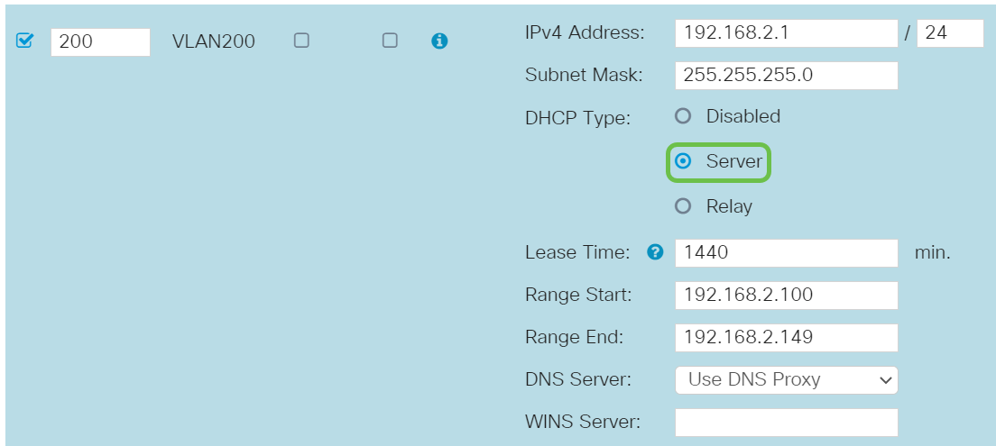
Select a Dynamic Host Configuration Protocol (DHCP) Type. The following options are:
Disabled – Disables the DHCP IPv4 server on VLAN. This is recommended in a test environment. In this scenario, all IP addresses would need to be manually configured and all communication would be internal.
Server - This is the most often used option.
Step 8
Click Apply to create the new VLAN.

Assign VLANs to Ports (Optional)
16 VLANs can be configured on the RV345P, with one VLAN for the Wide Area Network (WAN). VLANs that are not on a port should be Excluded. This keeps the traffic on that port exclusively for the VLAN/VLANs the user specifically assigned. It is considered a best practice.
Ports can be set to be an Access Port or a Trunk Port:
One VLAN assigned its own port:
Two or more VLANs that share one port:
Step 1
Select the VLAN IDs to edit.
In this example, we have selected VLAN 1 and VLAN 200.

Step 2
Click Edit to assign a VLAN to a LAN port and specify each setting as Tagged, Untagged, or Excluded.
In this example, on LAN1 we assigned VLAN 1 as Untagged and VLAN 200 as Excluded. For LAN2 we assigned VLAN 1 as Excluded and VLAN 200 as Untagged.

Step 3
Click Apply to save the configuration.

You should now have successfully created a new VLAN and configured VLANs to ports on the RV345P. Repeat the process to create the other VLANs. For example, VLAN300 would be created for Marketing with a subnet of 192.168.3.x and VLAN400 would be created for Accounting with a subnet of 192.168.4.x.
Add a Static IP (Optional)
If you would like a certain device to be reachable to other VLANs, you can give that device a static local IP address and create an access rule to make it accessible. This only works if Inter-VLAN routing is enabled. There are other situations where a static IP may be useful. For more information on setting static IP addresses, check out Best Practices for Setting Static IP Addresses on Cisco Business Hardware.
If you don’t need to add a static IP address, you can move to the next section of this article.
Step 1
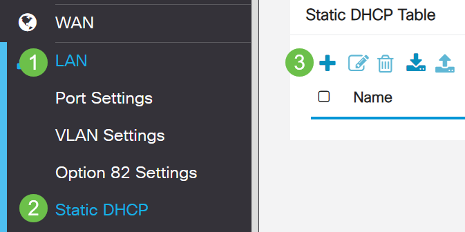
Navigate to LAN > Static DHCP. Click on the plus icon.
Step 2
Add the Static DHCP information for the device. In this example, the device is a printer.

Managing Certificates (Optional)
A digital certificate certifies the ownership of a public key by the named subject of the certificate. This allows relying parties to depend upon signatures or assertions made by the private key that corresponds to the public key that is certified. A router can generate a self-signed certificate, a certificate created by a network administrator. It can also send out requests to Certificate Authorities (CA) to apply for a digital identity certificate. It is important to have legitimate certificates from third party applications.
A Certificate Authority (CA) is used for authentication. Certificates can be purchased from any number of third-party sites. It is an official way to prove that your site is secure. Essentially, the CA is a trusted source that verifies that you are a legitimate business and can be trusted. Depending on your needs, a certificate at a minimal cost. You get checked out by the CA, and once they verify your information, they will issue the certificate to you. This certificate can be downloaded as a file on your computer. You can then go into your router (or VPN server) and upload it there.
Generate CSR/Certificate
Step 1
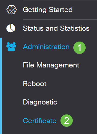
Log in to the web-based utility of the router and choose Administration > Certificate.
Step 2
Click Generate CSR/Certificate. You will be brought to the Generate CSR/Certificate page.

Step 3
Fill in the boxes with the following:
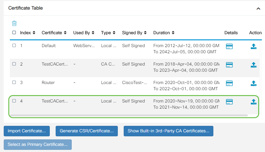
You should now have successfully created a certificate on the RV345P router.
Export a Certificate
Step 1
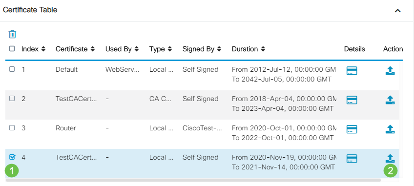
In the Certificate Table, check the checkbox of the certificate you want to export and click the export icon.
Step 2
Step 3
A message indicating the success of the download will appear below the Download button. A file will begin to download in your browser. Click Ok.
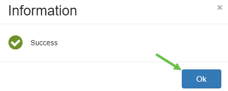
You should now have successfully exported a certificate on the RV345P Series Router.
Import a Certificate
Step 1
Click on Import Certificate....
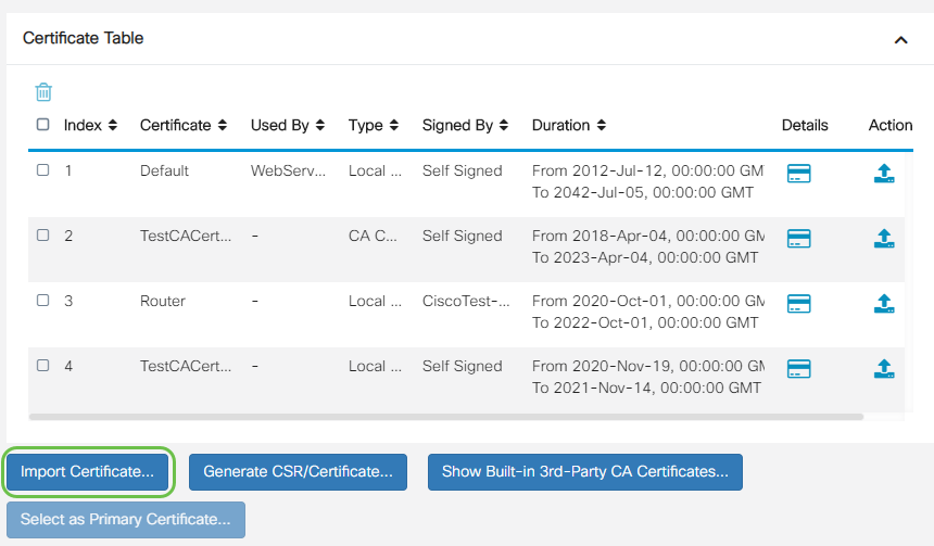
Step 2
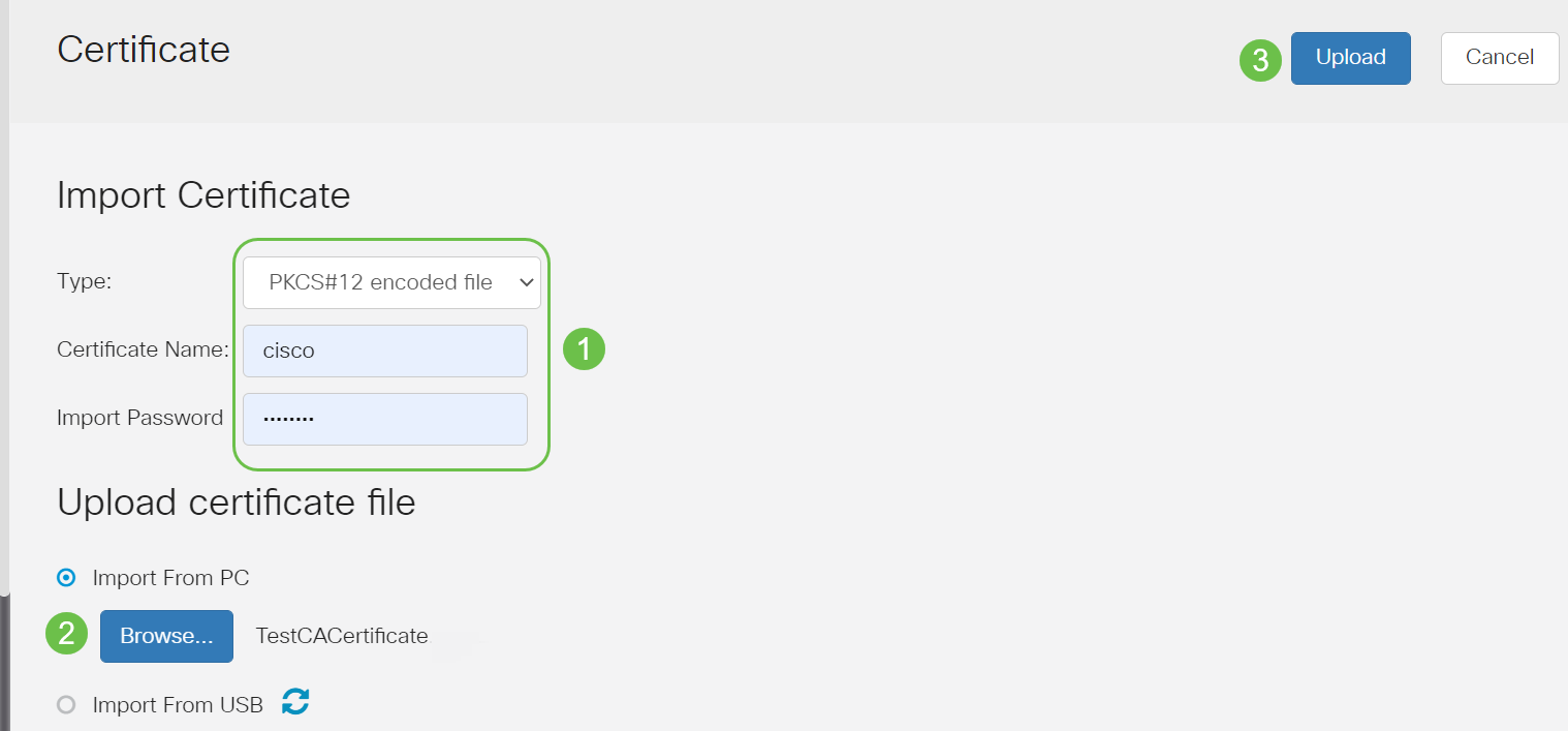
Once successful, you will automatically be taken to the main Certificate page. The Certificate Table will populate with the recently imported certificate.
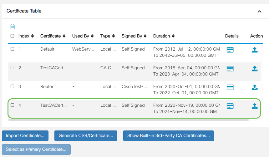
You should now have successfully imported a certificate on your RV345P router.
Configure a Mobile Network Using a Dongle and an RV345P Series Router (Optional)
Perhaps you want to configure a backup mobile network using a dongle and your RV345P router. If this is the case, you should read Configure a Mobile Network Using a Dongle and an RV34x Series Router.
Congratulations, you have completed the configuration of your RV345P router! You will now configure your Cisco Business Wireless devices.
Configure the Wireless Mesh Network
CBW140AC Out of the Box
Start by plugging an Ethernet cable from the PoE port on your CBW140AC to a PoE port on the RV345P. Half of the ports on the RV345P can supply PoE, so any of them can be used.
Check the status of the indicator lights. The access point will take about 10 minutes to boot. The LED will blink green in multiple patterns, alternating rapidly through green, red, and amber before turning green again. There may be small variations in the LED color intensity and hue from unit to unit. When the LED light is blinking green, proceed to the next step.
The PoE Ethernet uplink port on the Mobile Application AP can ONLY be used to provide an uplink to the LAN, and NOT to connect to any other Mobile Application capable or mesh extender devices.
If your access point isn’t new, out of the box, make sure it is reset to factory default settings for the CiscoBusiness-Setup SSID to show up in your Wi-Fi options. For assistance with this, check out How to Reboot and Reset to Factory Default Settings on RV345x Routers.
Set Up the 140AC Mobile Application Wireless Access Point
In this section, you will be using the mobile application to set up the Mobile Application Wireless Access point.
On the back of the 140AC, plug the cable that came with the AP into the yellow PoE plug your 140 AC. Plug the other end into one of the RV345P LAN ports.
If you have trouble connecting, refer to the Wireless Troubleshooting Tips section of this article.
Step 1
Download the Cisco Business Wireless App available on Google Play or the Apple App Store on your mobile device. You will need one of the following Operating Systems:
Step 2
Open the Cisco Business Application on your mobile device.

Step 3
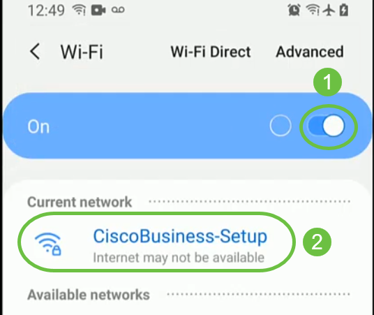
Connect to the CiscoBusiness-Setup wireless network on your mobile device. The passphrase is cisco123.
Step 4
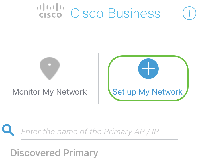
The app automatically detects the mobile network. Select Set up My Network.
Step 5
To set up the network enter the following:
Select Get Started.
Step 6
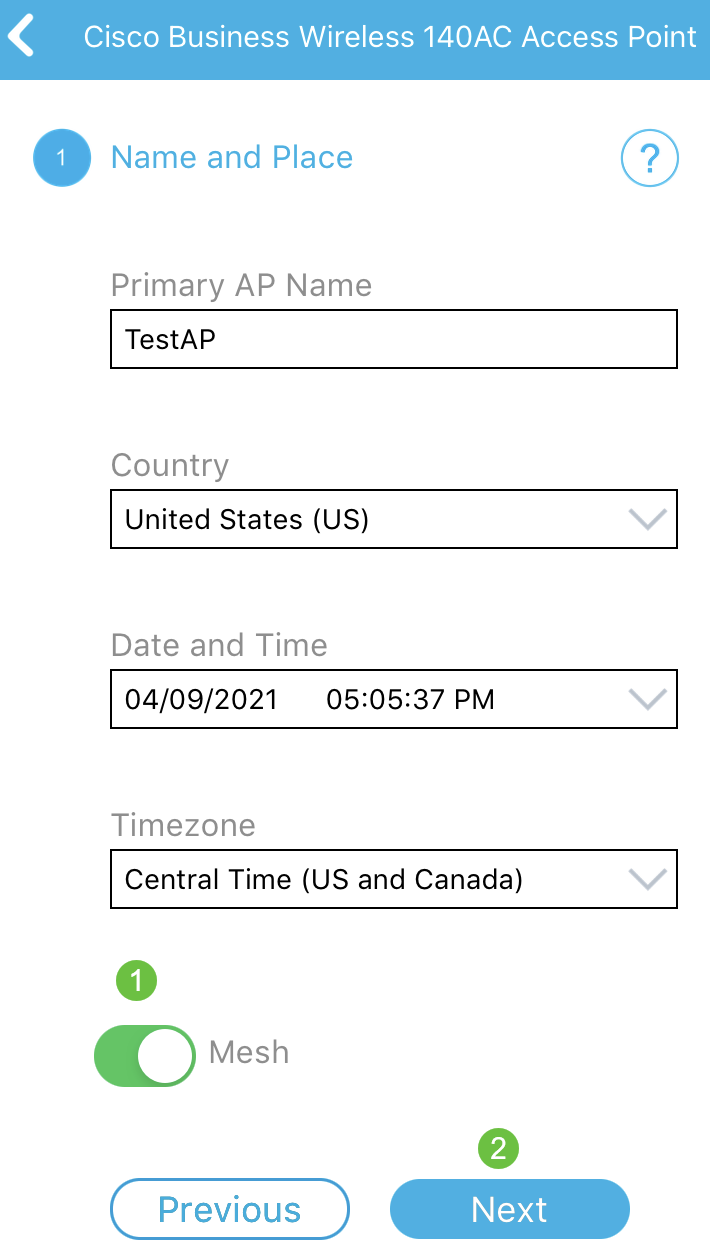
To configure Name and Place, accurately enter the following information. If you enter conflicting information, it can lead to unpredictable behavior.

Step 7
Turn on the toggle for Mesh. Click Next.
Step 8
(Optional) You can choose to enable Static IP for your Mobile Application AP for management purposes. If not, your DHCP server will assign an IP address. If you do not wish to configure static IP for your access point, click Next.
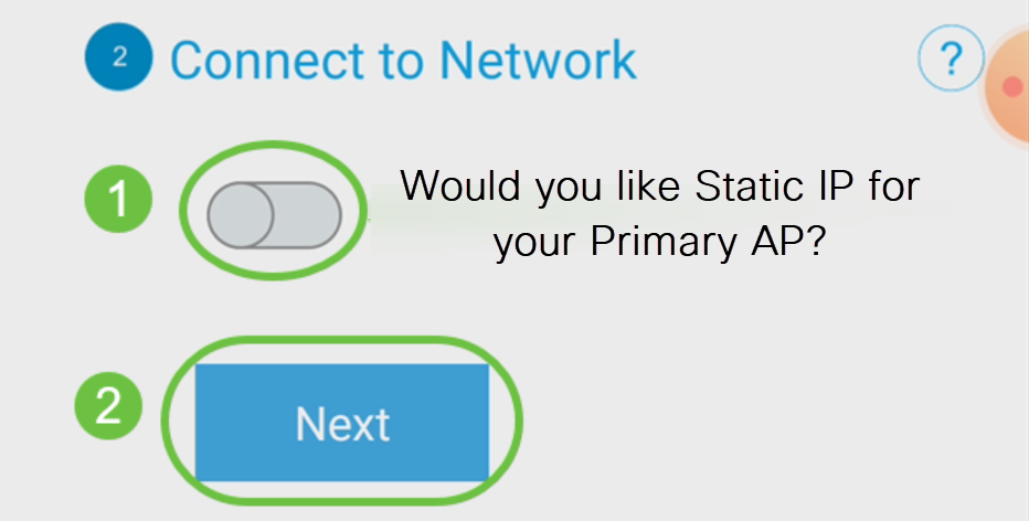
Alternatively, to Connect to Network:
Select Static IP for your Mobile Application AP. By default, this option is disabled.
Click Save.
Step 9
Configure the Wireless Network by entering the following:
Click Next.
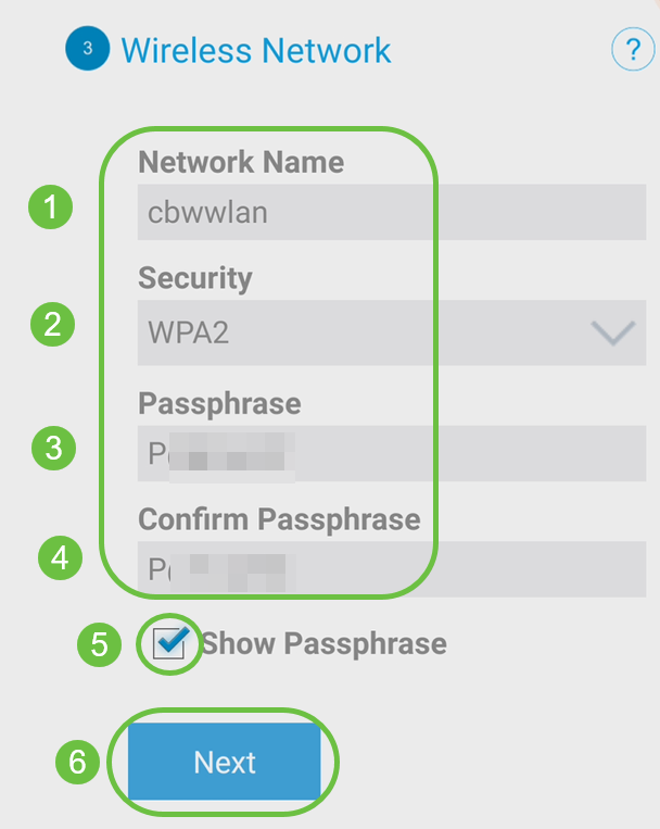
Wi-Fi protected Access (WPA) version 2 (WPA2), is the current standard for Wi-Fi security.
Step 10
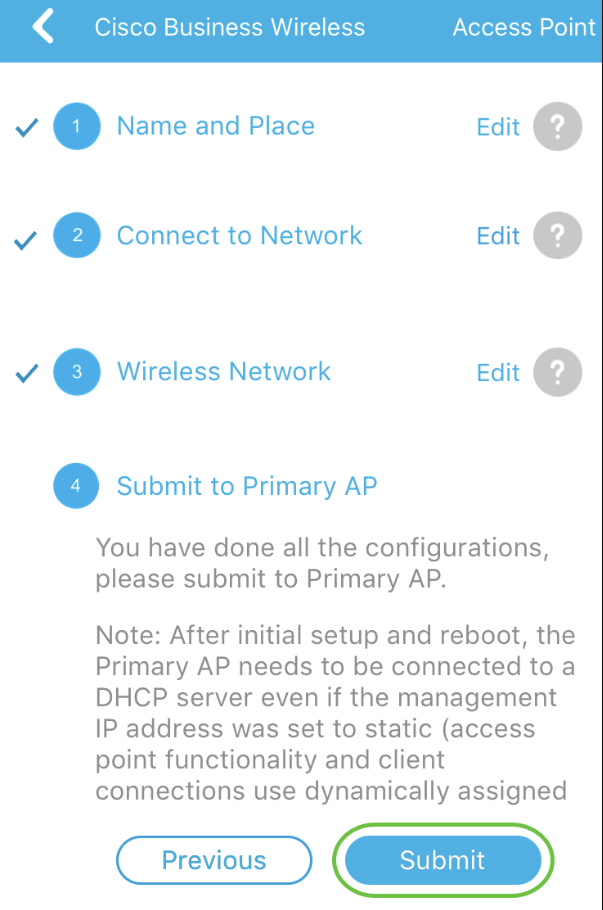
To confirm settings on the Submit to Mobile Application AP screen, click Submit.
Step 11
Wait for the reboot to complete.

The reboot can take up to 10 minutes. During a reboot, the LED in the access point will go through multiple color patterns. When the LED is blinking green, proceed to the next step. If the LED does not get past the red flashing pattern, it indicates that there is no DHCP server in your network. Ensure that the AP is connected to a switch or a router with a DHCP server.
Step 12
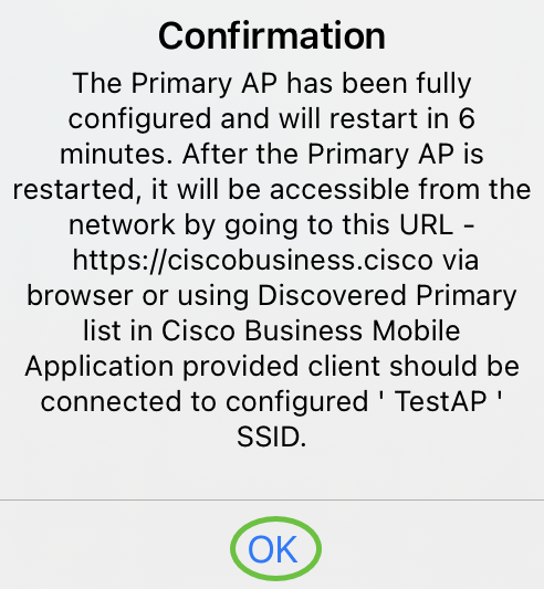
You will see the following Confirmation screen. Click OK.
Step 13
Close the app, connect to your newly created wireless network, and relaunch it to successfully complete the first part of your wireless network.
Wireless Troubleshooting Tips
If you have any issues, check out the following tips:
Configure the CBW142ACM Mesh Extenders
You are in the home stretch of setting up this network, you just need to add your mesh extenders!
Log into the Cisco Business app on your mobile device.
Step 1
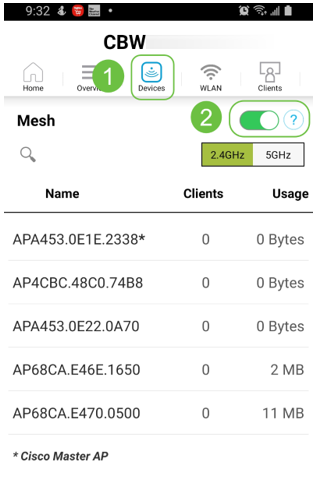
Navigate to Devices. Double-check that Mesh is enabled.
Step 2
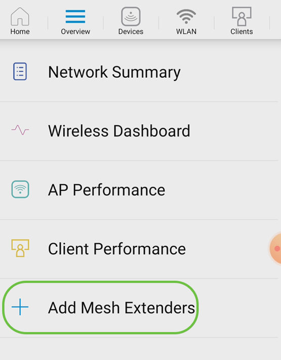
You must enter the MAC address of all Mesh Extenders that you want to use in the mesh network with the Mobile Application AP. To add the MAC address, click on Add Mesh Extenders from the menu.
Step 3
You can add the MAC address by either scanning a QR code or by manually entering the MAC address. In this example, Scan a QR code is selected.
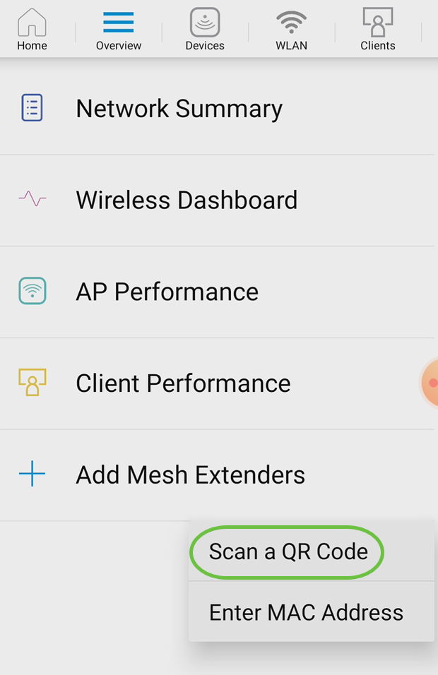
Step 4
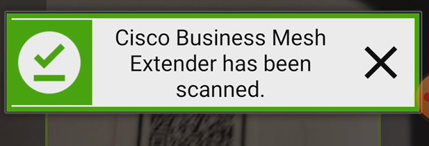
A QR code reader will appear to scan the QR code.

You will see the following screen once the QR code of the Mesh Extender has been scanned.
Step 5 (Optional)
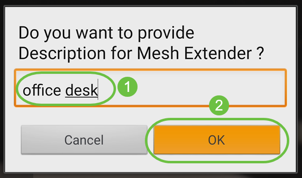
If you prefer, enter a Description for Mesh Extender. Click OK.
Step 6
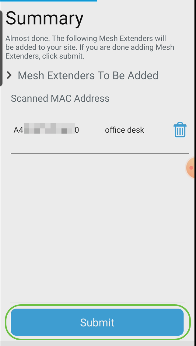
Review the Summary and click Submit.
Step 7
Click on Add More Mesh Extenders to add other mesh extenders to your network. Once your mesh extenders have all been added, click Done.
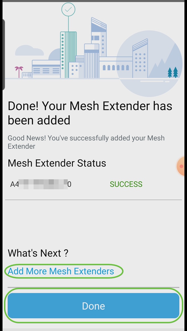
Repeat for each mesh extender.
You now have the basic settings ready to roll. Before you move on, make sure you check and update software if needed.
Check and Update Software on the Mobile App
Updating software is extremely important, so don’t skip this part!
Step 1
On your mobile app, under the More tab, click the Check for update button. Follow the prompts to update the software to the latest version.
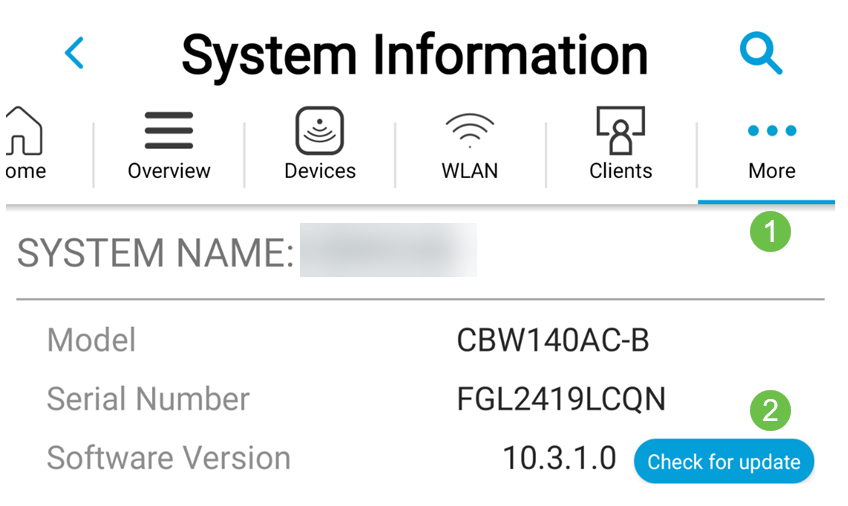
Step 2
You will see the download progress as it loads.
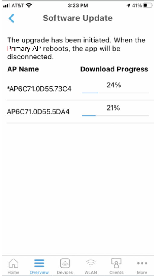
Step 3
A pop-up confirmation will notify you of the conclusion of the software upgrade. Click OK.
Create WLANs using the Mobile App
This section allows you to create Wireless Local Area Networks (WLANs).
Step 1
Open the Cisco Business Wireless App.

Step 2
Connect to your Cisco Business wireless network on your mobile. Log into the application. Click on the WLAN icon at the top of the page.
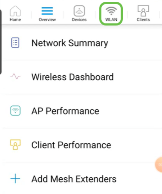
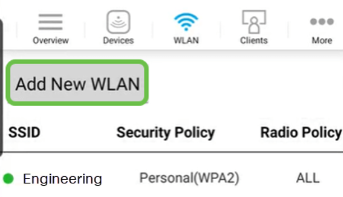
Step 3
The Add New WLAN screen opens. You will see the existing WLANs. Select Add New WLAN.
Step 4
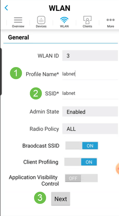
Enter a Profile Name and SSID. Fill in the rest of the fields or leave at the default settings. If you enabled Application Visibility Control, you will have other configurations explained in Step 6. Click Next.
Step 5 (Optional)
If you enabled Application Visibility Control in step 4, you may configure other settings, including a Guest Network, The details for this can be found in the next section. Captive Network Assistant, Security Type, Passphrase, and Password Expiry can be added here as well. When you have added all configurations, click Next.
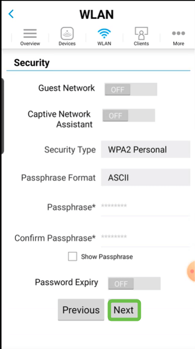
When using the mobile application, the only options for Security Type are Open or WPA2 Personal. For more advanced options, log into the Web UI of the Mobile Application AP instead.
Step 6 (Optional)
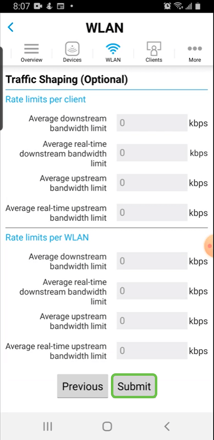
This screen gives you the options for Traffic Shaping. In this example, no traffic shaping has been configured. Click Submit.
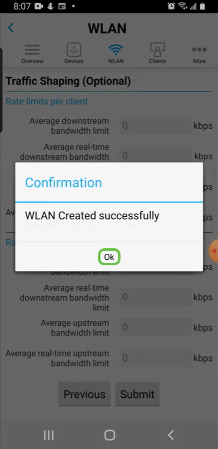
Step 7
You will see a confirmation pop-up. Click Ok.
Step 8
You will see the New WLAN added to the network as well as a reminder to save the configuration.
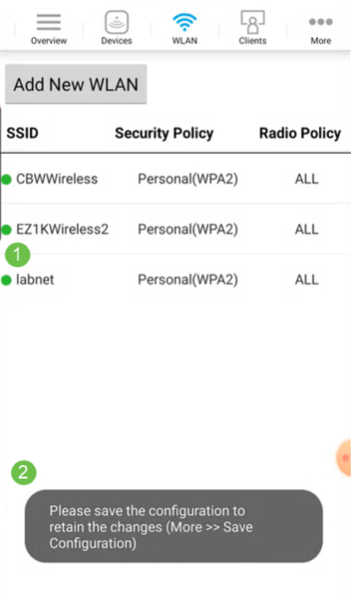
Step 9
Save your configuration by clicking the More tab and then select Save Configuration from the drop-down menu.

Create a Guest WLAN using the Mobile App
Step 1
Connect to your Cisco Business wireless network on your mobile device. Log into the application.

Step 2
Click on the WLAN icon at the top of the page.
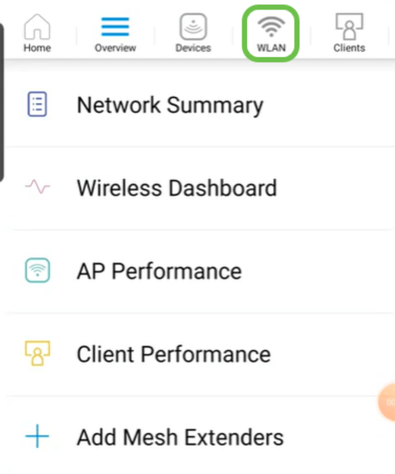
Step 3
The Add New WLAN screen opens. You will see any existing WLANs. Select Add New WLAN.

Step 4
Enter a Profile Name and SSID. Fill in the rest of the fields or leave at the default settings. Click Next.
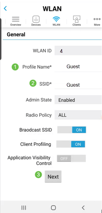
Step 5
Turn on Guest Network. In this example, Captive Network Assistant is also toggled on, but this is optional. You have options for Access Type. In this case, Social Login is selected.
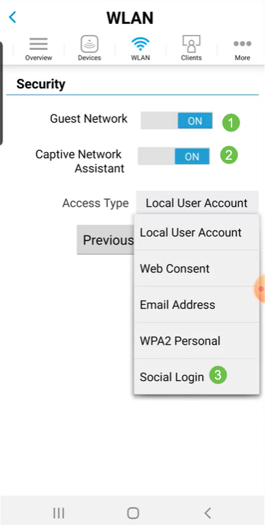
Step 6
This screen gives you the options for Traffic Shaping (Optional). In this example, no traffic shaping has been configured. Click Submit.

Step 7
You will see a confirmation pop-up. Click Ok.

Step 8
Save your configuration by clicking the More tab and then select Save Configuration from the drop-down menu.

Conclusion
You now have a complete set up for your network. Take a minute to celebrate and then get to work!
If you want to add Application Profiling or Client Profiling to your wireless mesh network, you will want to use the Web User Interface (UI). Click to set up these features.
We want the best for our customers, so you have any comments or suggestions regarding this topic, please send us an email to the Cisco Content Team.
If you would like to read other articles and documentation, check out the support pages for your hardware: