Link Aggregation Group (LAG) Management and Settings on Sx500 Series Stackable Switches
Available Languages
Objective
Link Aggregation Group (LAG) multiply the bandwidth, increase port flexibility, and provide link redundancy between two devices. Link Aggregation Control Protocol (LACP) is a part of IEEE specification (802.3az) that can control the bundling of several physical ports together to form a single logical channel (LAG). Traffic load balancing over the active member ports of a LAG is managed by a hash-based distribution function that distributes unicast and multicast traffic based on Layer 2 or Layer 3 packet header information. LACP helps to form one single LAG by bundling many physical ports. It is also responsible for bandwidth multiplication, increase in port flexibility, and in providing redundancy on links between any 2 devices. Additionally this helps in changing the LAG speed, advertisement, flow control, and also protection which can be easily identified in LAG settings table.
This document shows you how to configure the load balancing algorithm, LAG management, and LAG settings on a switch.
Note: For instructions on how to configure LAG on a switch through the CLI (Command Line Interface), click here.
Applicable Devices
- Sx500 Series Stackable Switches
- Sx350X Series Switches
- Sx550X Series Switches
Software Version
- v2.3.5.63 (Sx350X & Sx550X)
- v1.4.9.4 (Sx500)
LAG Management Procedure
Configure Load Balance Algorithm
The steps in this document are performed under the advanced display mode using the SG550X-24. To change to the advanced display mode, go to the top right corner and select Advanced in the Display Mode drop-down list.

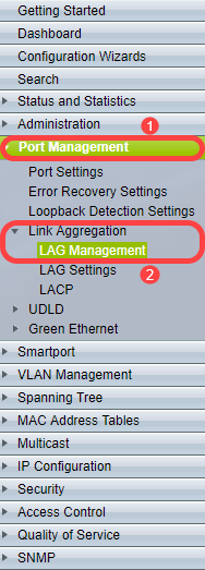
Step 1. Log in to the web configuration utility and choose Port Management > Link Aggregation > LAG Management. The LAG Management page opens:
Step 2. Click one of the following radio buttons for the Load Balance Algorithm. In this example, we will be configure IP/MAC address as our load balance algorithm.
- MAC Address - Performs load balancing based on source and destination MAC addresses on all the packets.
- IP/MAC Address - Performs load balancing by the source and destination IP addresses on IP packets, and by the source and destination MAC addresses on non-IP packets.
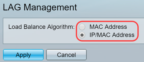
Step 3. Click the Apply button to apply the changes. The Running Configuration file is updated.

Edit LAG Management
Step 1. To define member or candidate port in the LAG Management Table section, click the radio button for the LAG to be configured.
The descriptions of the fields in the LAG Management Table are:
- LAG - LAGs are shown in the column.
- Name - LAG name configured is shown in the column.
- LACP - Shows whether LACP is enabled or disabled to the particular LAG.
- Link State - Shows whether the LINK of the LAG is active or down.
- Active Member - Shows the member which are in the field and are active in the configured set.
- Standby Member - Shows the members which are configured to the LAG members which are on standby.

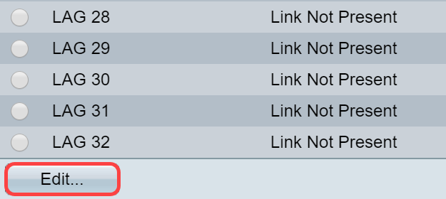
Step 2. Click Edit... to modify the LAG.
Step 3. (Optional) Choose the LAG number from the LAG drop-down list.
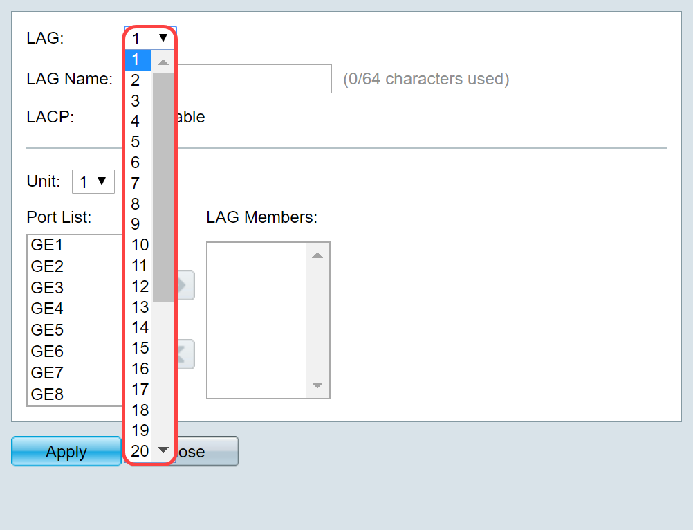
Step 4. Enter a name for the LAG in the LAG Name field.

Step 5. Check Enable in the LACP field on the chosen LAG. This makes it a dynamic LAG. This field can only be enabled after moving a port to the LAG in the next field.

Step 6. Choose the Unit of the switch from the Unit field which displays the stacking member for which LAG information is defined.
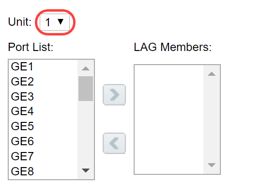
Step 7. Move the ports that are to be assigned to the LAG from the Port List to the LAG Members list. Up to eight ports per static LAG and 16 ports to a dynamic LAG can be assigned. The chosen Unit/Slot and the Port list are added to the LAG Members list. In this example, we will be selecting GE1 and GE2.
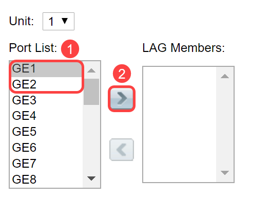
Step 8. Click Apply to save the changes in the Edit LAG Membership page.
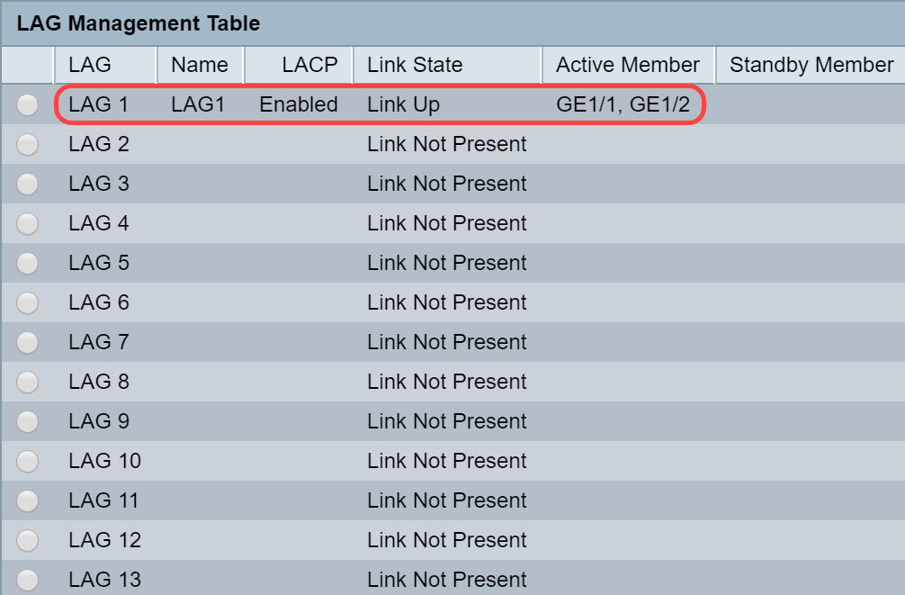
Note: LAG will also need to be configured on the other switch as well. If LAG is not configured on the other switch, then the Link State will be Link Down and the ports that you have configured will be in Standby Member field.
Configure LAG Settings
The following configuration procedure not only helps you to configure LAG but also to reactivate suspended LAG.
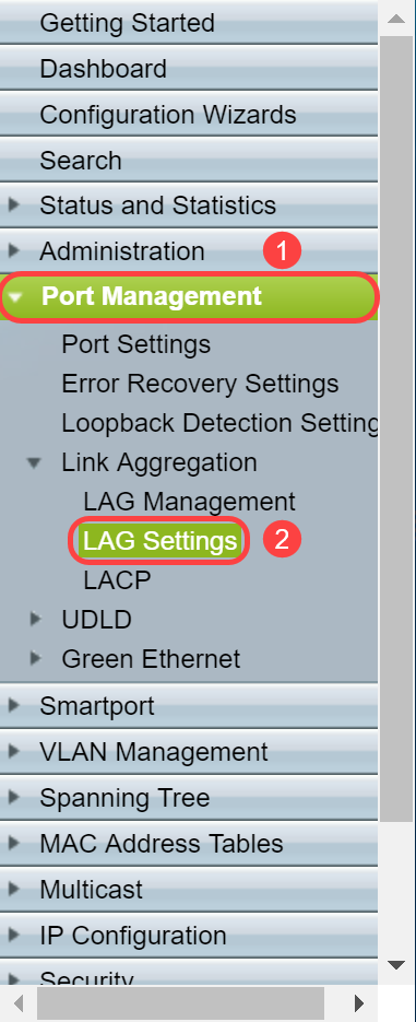
Step 1. Log in to the web configuration utility and choose Port Management > Link Aggregation > LAG Settings. The LAG Settings page opens:
Step 2. Click the LAG that needs to be modified.

Step 3. Click Edit to modify that LAG.

Step 4. The Edit LAG Settings window appears. Choose the LAG ID number from the LAG drop-down list.
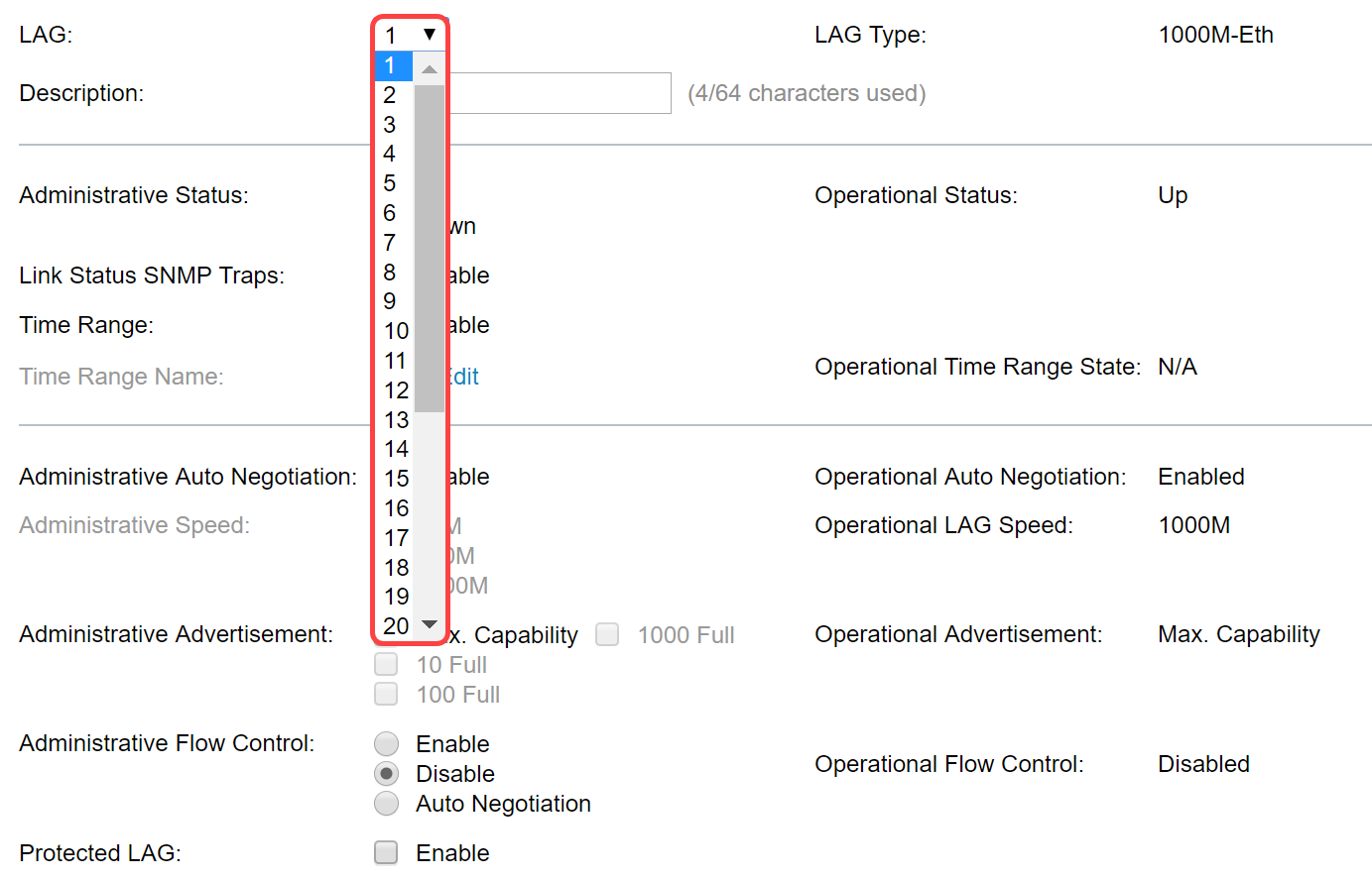
Step 5. In the Description field, enter the LAG name or a comment for identification. The LAG Type field will display the port type that comprises the LAG.

Step 6. Select the LAG to be administratively Up or Down in the Administrative Status field. The Operational Status field shows whether LAG is currently operating.

Step 7. Check the Enable checkbox in the Link Status SNMP traps field if you want to enable generation of SNMP traps notifying of changes to the link status of the ports in the LAG. Link status SNMP traps is enabled by default.

Step 8. (Optional) In the Time Range field, check the Enable checkbox to enable the time range during which the port is in up state. When the time range is not active, the port is in shutdown. If a time range is configured, it is effective only when the port is administratively up. Time range is not enabled by default. In this example, we will be leaving time range disabled.
Note: This field may vary depending on the switch model you are using.

Step 9. (Optional) If Time Range was enabled in the previous step, select the profile that specifies the time range in the Time Range Name field. If a time range is not yet defined, click Edit to go to the Time Range page.
Note: Time range needs to be enabled in order to select a time range name.

Step 10. Check the Enable checkbox in the Administrative Auto Negotiation field to enable or disable auto-negotiation on the LAG. Auto-negotiation is a protocol between two link partners that enables a LAG to advertise its transmission speed and flow control to its partner (the Flow Control default is disabled). The Operational Auto Negotiation field displays the auto-negotiation settings.
Note: It is recommended to keep auto-negotiation enabled on both sides of an aggregate link, or disabled on both sides, while ensuring that link speeds are identical.

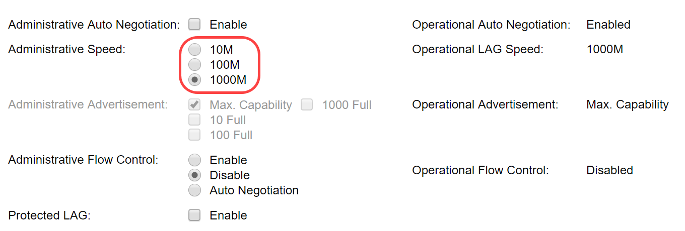
Step 11. (Optional) If Administrative Auto Negotiation is disabled in the previous step, select the Administrative Speed. The Operational Lag Speed displays the current speed at which the LAG is operating.
The available speeds are:
- 10M
- 100M
- 1000M
Note: The speed may vary depending on the model of your switch.
Step 12. In the Administrative Advertisement field, check the capabilities to be advertised by the LAG. The Operational Advertisement displays the administrative advertisement status. The LAG advertises its capabilities to its neighbor LAG to start the negotiation process. The possible values are:
- Max Capability - All LAG speeds and both duplex modes are available.
- 10 Full - The LAG advertises a 10 Mbps speed and the mode is full duplex.
- 100 Full - The LAG advertises a 100 Mbps speed and the mode is full duplex.
- 1000 Full - The LAG advertises a 1000 Mbps speed and the mode is full duplex.

Step 13. Select one of the options in the Administrative Flow Control field. Flow control is a feature that allows the receiving device to send a signal to the sending device that it's congested. This tells the sending device to temporarily stop transmitting to help ease the congestion. The Operational Flow Control shows the current flow control setting. In this example, we will be enabling flow control.
The options are:
- Enable
- Disable
- Auto Negotiation

Step 14. Check the Enable checkbox in the Protected LAG to make the LAG a protected port for Layer 2 isolation. In this example, we will enable protected LAG.

Step 15. Click Apply. The Running Configuration file is updated.
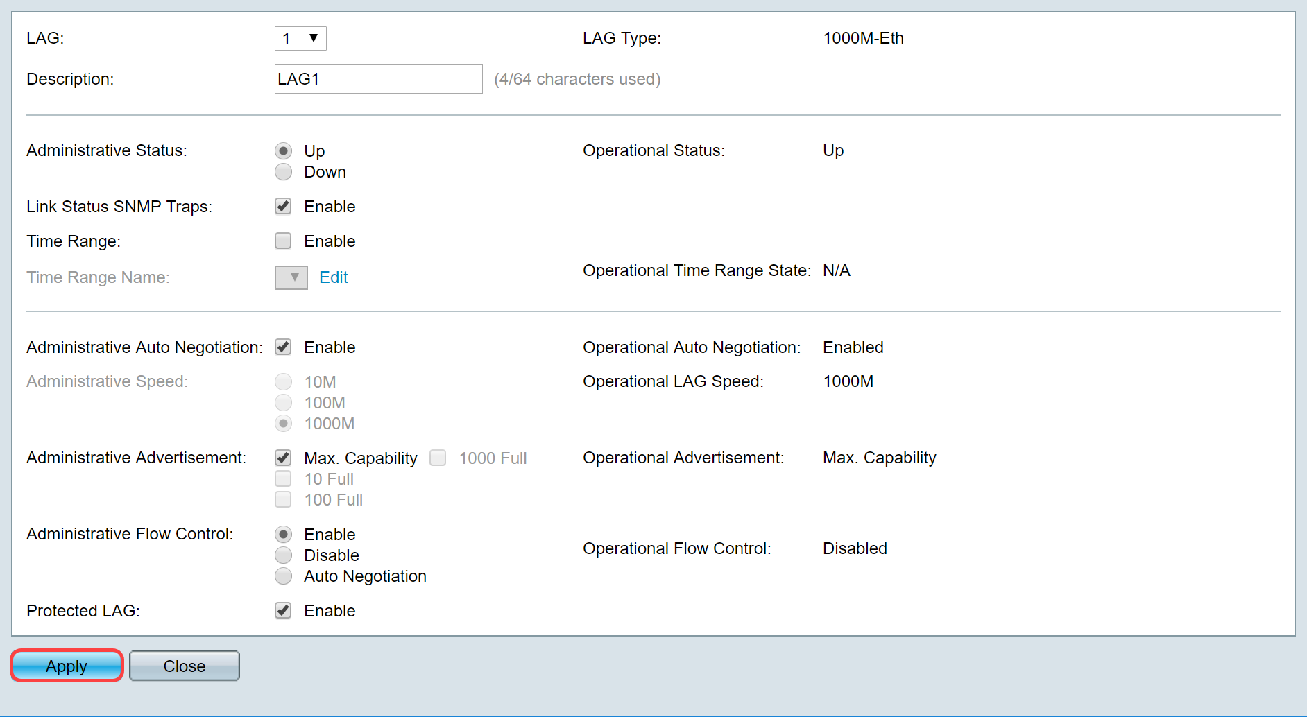
Note: The LAG Setting Table is updated with the modified configuration.

You have now learned the steps to configure the load balancing algorithm, LAG management, and LAG settings on a switch.
Revision History
| Revision | Publish Date | Comments |
|---|---|---|
1.0 |
13-Dec-2018 |
Initial Release |
 Feedback