Configure STP Settings on a Switch through the CLI
Available Languages
Objective
Spanning Tree Protocol (STP) protects Layer 2 broadcast domains from broadcast storms by selectively setting links to standby mode to prevent loops. In standby mode, these links temporarily stop transferring user data. After the topology changes, so that the data transfer is made possible, the links are automatically re-activated.
Network Loops occur when there are alternate routes between hosts. These loops cause Layer 2 switches to forward traffic across the network infinitely, reducing network efficiency. STP provides a unique path between endpoints on a network. These paths eliminate the possibility of network loops. STP is typically configured when there are redundant links to a host to prevent network loop.
The device supports the following Spanning Tree Protocol versions:
- Classic STP — Provides a single path between any two end stations, avoiding and eliminating loops.
- Rapid STP (RSTP) — Detects network topologies to provide faster convergence of the spanning tree. This is most effective when the network topology is naturally tree-structured, and therefore faster convergence might be possible. RSTP is enabled by default.
- Multiple STP (MSTP) — MSTP is based on RSTP. It detects Layer 2 loops, and attempts to mitigate them by preventing the involved port from transmitting traffic. Since loops exist on a per-Layer 2-domain basis, a situation can occur when a port is blocked to eliminate an STP loop. Traffic will be forwarded to the port that is not blocked, and no traffic will be forwarded to the port that is blocked. This is not an efficient usage of bandwidth as the blocked port will always be unused.
MSTP solves this problem by enabling several STP instances, so that it is possible to detect and mitigate loops separately in each instance. This enables a port to be blocked for one or more STP instances but non-blocked for other STP instances. If different VLANs are associated with different STP instances, then their traffic will be relayed based on the STP port state of their associated MST instances. This results to better bandwidth utilization.
This article aims to show you how to configure STP on a switch through the CLI.
Applicable Devices
- Sx300 Series
- Sx350 Series
- SG350X Series
- Sx500 Series
- Sx550X Series
Software Version
- 1.4.7.06 — Sx300, Sx500
- 2.2.8.04 — Sx350, SG350X, Sx550X
Configure Spanning Tree Properties
Step 1. Log in to the switch console. The default username and password is cisco/cisco. If you have configured a new username or password, enter the credentials instead.
Note: To learn how to access an SMB switch CLI through SSH or Telnet, click here.

Note: The commands may vary depending on the exact model of your switch. In this example, the SG350X-48MP switch is accessed through Telnet.
Step 2. From the Privileged EXEC mode of the switch, enter the Global Configuration mode by entering the following:

Step 3. To enable the STP functionality on the switch, enter the following:


Step 4. To configure the STP protocol to run on the switch, enter the following:

The options are:
- stp — Classic STP provides a single path between any two endpoints, eliminating and preventing networking loops.
- rstp — RSTP detects network topologies to provide faster convergence of the spanning tree. This option is enabled by default.
- mst — MSTP is based on RSTP. It detects Layer 2 loops, and attempts to mitigate them by preventing the involved port from transmitting traffic.

Note: In this example, rstp is used.
Step 5. To set the default path cost method, enter the following:

The options are:
- long — Specifies the value for port path costs. The range is from one up to 200000000.
- short — Specifies the value for port path costs. The range is from one to 65535.

Step 6. To configure the switch STP priority, which is used to determine which bridge is selected as the root bridge, enter the following:

- priority-number — Specifies the bridge priority. The range is from 0 up to 61440.

Note: In this example, 32768 is used.
Step 7. (Optional) To configure how often the switch broadcasts Hello messages to other devices, enter the following:

- seconds — Specifies the spanning tree Hello time in seconds. The range is from 1 up to 10 seconds. The default value is 2 seconds.

Note: In this example, the default Hello time of 2 seconds is used.
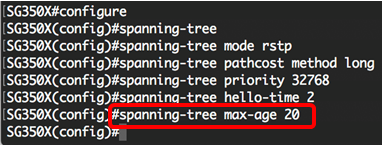
Step 8. (Optional) To configure the STP maximum age, enter the following:

- seconds — Specifies the spanning tree bridge maximum age in seconds. The range is from six up to 40 seconds. The default value is 20 seconds.

Note: In this example, the default value of 20 seconds is used.
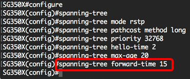
Step 9. (Optional) To configure the STP bridge forward time, which is the amount of time a port remains in the listening and learning states before entering the forwarding state, enter the following:

- seconds — Specifies the spanning tree forward time in seconds. The range is from four up to 30 seconds. The default value is 15 seconds.

Note: In this example, the default value of 15 seconds is used.
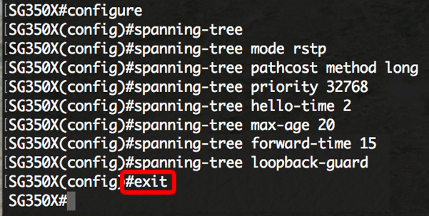
Step 10. (Optional) To enable STP Loopback Guard, enter the following:

Note: Enabling this feature checks if a root port or an alternate root port receives Bridge Protocol Data Units (BPDUs). In this example, STP Loopback Guard is enabled.

Step 11. Enter the exit command to go back to the Privileged EXEC mode:


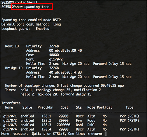
Step 12. (Optional) To display the STP settings on the switch, enter the following:


Step 13. (Optional) In the Privileged EXEC mode of the switch, save the configured settings to the startup configuration file by entering the following:


Step 14. (Optional) Press Y for Yes or N for No on your keyboard once the Overwrite file [startup-config]… prompt appears.

You should now have successfully configured the STP settings on your switch through the CLI.
Revision History
| Revision | Publish Date | Comments |
|---|---|---|
1.0 |
13-Dec-2018 |
Initial Release |
 Feedback