Configure Private VLAN Membership Settings on a Switch through the CLI
Available Languages
Introduction
A Virtual Local Area Network (VLAN) allows you to logically segment a Local Area Network (LAN) into different broadcast domains. In scenarios where sensitive data may be broadcast on a network, VLANs can be created to enhance security by designating a broadcast to a specific VLAN. Only users that belong to a VLAN are able to access and manipulate the data on that VLAN. VLANs can also be used to enhance performance by reducing the need to send broadcasts and multicasts to unnecessary destinations.
Note: To learn how to configure the VLAN settings on your switch through the web-based utility, click here. For CLI-based instructions, click here.
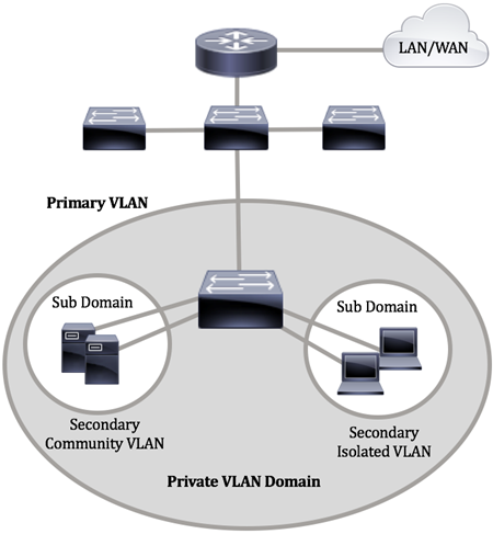
A Private VLAN domain consists of one or more pairs of VLANs. The primary VLAN makes up the domain; and each VLAN pair makes up a subdomain. The VLANs in a pair are called the primary VLAN and the secondary VLAN. All VLAN pairs within a private VLAN have the same primary VLAN. The secondary VLAN ID is what differentiates one subdomain from another.

A private VLAN domain has only one primary VLAN. Each port in a private VLAN domain is a member of the primary VLAN; the primary VLAN is the entire private VLAN domain.
Secondary VLANs provide isolation between ports within the same private VLAN domain. The following two types are secondary VLANs within a primary VLAN:
- Isolated VLANs — Ports within an isolated VLAN cannot communicate directly with each other at the Layer 2 level.
- Community VLANs — Ports within a community VLAN can communicate with each other but cannot communicate with ports in other community VLANs or in any isolated VLANs at the Layer 2 level.
Within a private VLAN domain, there are three separate port designations. Each port designation has its own unique set of rules which regulate the ability of one endpoint to communicate with other connected endpoints within the same private VLAN domain. The following are the three port designations:
- Promiscuous — A promiscuous port can communicate with all ports of the same private VLAN. These ports connect servers and routers.
- Community (host) — Community ports can define a group of ports that are member in the same Layer 2 domain. They are isolated at Layer 2 from other communities and from isolated ports. These ports connect host ports.
- Isolated (host) — An isolated port has complete Layer 2 isolation from the other isolated and community ports within the same private VLAN. These ports connect host ports.
Host traffic is sent on isolated and community VLANs, while server and router traffic is sent on the primary VLAN.
Objective
A Private VLAN provides layer-2 isolation between ports. This means that at the level of bridging traffic, as opposed to IP routing, ports that share the same broadcast domain cannot communicate with each other. The ports in a private VLAN can be located anywhere in the layer 2 network, which means they do not have to be on the same switch. The private VLAN is designed to receive untagged or priority-tagged traffic and transmit untagged traffic.
This article provides instructions on how to configure private VLAN settings on a switch.
Note: To configure the private VLAN using the web-based utility of the switch, click here.
Applicable Devices
- Sx300 Series
- Sx350 Series
- SG350X Series
- Sx500 Series
- Sx550X Series
Software Version
- 1.4.7.06 — Sx300, Sx500
- 2.2.8.04 — Sx350, SG350X, Sx550X
Configure Private VLAN Settings on the Switch through the CLI
Create a Private Primary VLAN
Step 1. Log in to the switch console. The default username and password is cisco/cisco. If you have configured a new username or password, enter the credentials instead.

Note: The commands may vary depending on the exact model of your switch. In this example, the SG350X switch is accessed through Telnet.
Step 2. From the Privileged EXEC mode of the switch, enter the Global Configuration mode by entering the following:

Step 3. In the Global Configuration mode, enter the Interface Configuration context by entering the following:

- vlan-id — Specifies the VLAN ID to be configured.

Note: In this example, VLAN 2 is used.
Step 4. In the Interface Configuration context, configure the VLAN interface as the primary private VLAN by entering the following:

Note: By default, there are no private VLANs configured on the switch.

Important: Make sure to remember the following guidelines in configuring a private VLAN:
- The VLAN type cannot be changed if there is a private VLAN port that is a member in the VLAN.
- The VLAN type cannot be changed if it is associated with other private VLANs.
- The VLAN type is not kept as a property of the VLAN when the VLAN is deleted.
Step 5. (Optional) To return the VLAN to its normal VLAN configuration, enter the following:

Step 6. (Optional) To go back to the Privileged EXEC mode of the switch, enter the following:


Step 7. (Optional) In the Privileged EXEC mode of the switch, save the configured settings to the startup configuration file, by entering the following:


Step 8. (Optional) Press Y for Yes or N for No on your keyboard once the Overwrite file [startup-config]… prompt appears.

You should now have successfully created the primary VLAN on your switch through the CLI.
Create a Secondary VLAN
Step 1. In the Privileged EXEC mode of the switch, enter the Global Configuration mode by entering the following:

Step 2. In the Global Configuration mode, enter the Interface Configuration context by entering the following:


Note: In this example, VLAN 10 is used.
Step 3. In the Interface Configuration context, configure the VLAN interface as the secondary private VLAN by entering the following:

The options are:
- community — Designate the VLAN as a community VLAN.
- isolated — Designate the VLAN as an isolated VLAN.

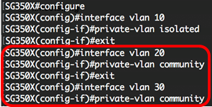
Note: In this example, VLAN 10 is configured as an isolated VLAN.
Step 4. (Optional) Repeat steps 2 and 3 to configure additional secondary VLAN for your private VLAN.

Note: In this example, VLAN 20 and VLAN 30 are configured as community VLANs.
Step 5. (Optional) To return the VLAN to its normal VLAN configuration, enter the following:

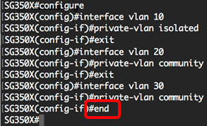
Step 6. (Optional) To go back to the Privileged EXEC mode of the switch, enter the following:


You should now have successfully created secondary VLANs on your switch through the CLI.
Associate the Secondary VLAN to the Primary Private VLAN
Step 1. In the Privileged EXEC mode of the switch, enter the Global Configuration mode by entering the following:

Step 2. Enter the VLAN Interface Configuration context of the primary VLAN by entering the following:


Note: In this example, the primary VLAN is VLAN 2.
Step 3. To configure the association between the primary VLAN and secondary VLANs, enter the following:

The options are:
- add secondary-vlan-list — List of VLAN IDs of type secondary to add to a primary VLAN. Separate nonconsecutive VLAN IDs with a comma and no spaces. Use a hyphen to designate a range of IDs. This is the default action.
- remove secondary-vlan-list — List of VLAN IDs of type secondary to remove association from a primary VLAN. Separate nonconsecutive VLAN IDs with a comma and no spaces. Use a hyphen to designate a range of IDs.

Note: In this example, secondary VLANs 10, 20, and 30 are added to the primary VLAN.
Step 4. To go back to the Privileged EXEC mode of the switch, enter the following:


You should now have successfully associated the secondary VLANs to the primary private VLAN on your switch through the CLI.
Configure Ports to the Primary and Secondary Private VLANs
Step 1. In the Privileged EXEC mode of the switch, enter the Global Configuration mode by entering the following:

Step 2. In the Global Configuration mode, enter the Interface Configuration context by entering the following:

The options are:
- interface-id — Specifies an interface ID to be configured.
- range vlan vlan-range — Specifies a list of VLANs. Separate nonconsecutive VLANs with a comma and no spaces. Use a hyphen to designate a range of VLANs.

Note: In this example, an interface ge1/0/10 is entered.
Step 3. In the Interface Configuration context, use the switchport mode command to configure the VLAN membership mode.

- promiscuous — Specifies a private VLAN promiscuous port. If this option is used, skip to Step 5.
- host — Specifies a private VLAN host port. If this option is used, skip to Step 6.
Note: In this example, the port is defined as promiscuous.

Step 4. (Optional) To return the port or range of ports to the default configuration, enter the following:

Step 5. To configure the association of a promiscuous port with primary and secondary VLANs of the private VLAN, enter the following:

The options are:
- primary-vlan-id — Specifies the VLAN ID of the primary VLAN.
- secondary-vlan-id — Specifies the VLAN ID of the secondary VLAN.
Note: In this example, the promiscuous interface is mapped to primary VLAN 2 and added to secondary VLAN 30.

Step 6. To configure the association of a host port with primary and secondary VLANs of the private VLAN, enter the following:

The options are:
- primary-vlan-id — Specifies the VLAN ID of the primary VLAN.
- secondary-vlan-id — Specifies the VLAN ID of the secondary VLAN.
Note: In this example, the host interface range 40 to 45 are mapped to primary VLAN 2 and added to secondary VLAN 20.

Step 7. To exit the Interface Configuration context, enter the following:

Step 8. (Optional) Repeat steps 2 to 7 to configure more promiscuous and host ports and assign to the corresponding primary and secondary private VLANs.
Note: In this example, the host interface range 36 to 39 are mapped to primary VLAN 2 and added to secondary VLAN 10.

Step 9. Enter the end command to go back to the Privileged EXEC mode:


Step 10. (Optional) To verify the configured private VLANs on your switch, enter the following:


Step 11. (Optional) In the Privileged EXEC mode of the switch, save the configured settings to the startup configuration file, by entering the following:


Step 12. (Optional) Press Y for Yes or N for No on your keyboard once the Overwrite file [startup-config]… prompt appears.

You should now have successfully configured the association of host and promiscuous ports with primary and secondary private VLANs on your switch through the CLI.
Revision History
| Revision | Publish Date | Comments |
|---|---|---|
1.0 |
13-Dec-2018 |
Initial Release |
 Feedback