Configure Green Ethernet Port Settings on a Switch through the Command Line Interface (CLI)
Available Languages
Objective
Green Ethernet is a common name for a set of features that is designed to be environmentally friendly and reduce the power consumption of a device. Unlike Energy Efficient Ethernet (EEE), Green Ethernet energy-detection is enabled on all ports whereas only devices with gigabyte ports are enabled with EEE.
The Green Ethernet feature can reduce overall power usage in the following ways:
- Energy Detect Mode — On an inactive link, the port moves into inactive mode and saves power while keeping the Administrative status of the port Up. Recovery from this mode to full operational mode is fast, transparent, and no frames are lost. This mode is supported on both Gigabit Ethernet (GE) and Fast Ethernet (FE) ports. This mode is disabled by default.
- Short Reach Mode — This feature provides power savings on a short length of cable. After cable length is analyzed, the power usage is adjusted for various cable lengths. If the cable is shorter than 30 meters for Ten-Gigabit ports and 50 meters for other type of ports, the device uses less power to send frames over the cable, thus saving energy. This mode is only supported on RJ45 GE ports and does not apply to Combo ports. This mode is disabled by default.
Green Ethernet settings can be configured globally and/or per switch interface. This article provides instructions on how to configure the Green Ethernet port settings on a switch through the Command Line Interface (CLI).
Note: To learn how to configure the Green Ethernet port settings on a switch through the web-based utility, click here for instructions.
Applicable Devices
- Sx300 Series
- Sx350 Series
- SG350X Series
- Sx500 Series
- Sx550X Series
Software Version
- 1.4.7.05 — Sx300, Sx500
- 2.2.8.4 — Sx350, SG350X, Sx550X
Configure Green Ethernet Port Settings on a Switch through the CLI
View Green Ethernet Port Settings on a Switch
Step 1. Log in to the switch console. The default username and password is cisco/cisco.

Note: The available commands or options may vary depending on the exact model of your device. In this example, the SG350X switch is accessed through Telnet.
Step 2. To display the current Green Ethernet configuration and information on the switch, enter the following command in the Privileged EXEC mode:

The options are:
- interface-id — (Optional) Displays the current Green Ethernet information on a specific Ethernet port.
- detailed — (Optional) Displays the current Green Ethernet information for the switch and its ports.
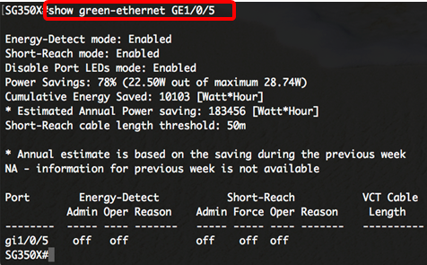
Note: In this example, show green-ethernet GE1/0/5 command is used to display the Green Ethernet information on a specific interface.

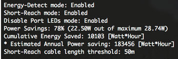
The Energy-Detect mode area displays current status of Energy Detect Mode in the switch. This is used to conserve power when the device is not connected to an active link partner.
The Short-Reach mode area displays current status of Short Reach in the switch. This allows you to run the links with less power than the link can normally handle.
The Disable Port LEDs mode area displays the current status of the Port Light-emitting Diodes (LEDs) in the switch. When this option is disabled, the LEDs do not display link status, activity, and so on. The Disable Port LEDs feature saves power consumed by device LEDs. Since the devices are often in an unoccupied room, having these LEDs lit is a waste of energy. The Green Ethernet feature allows you to disable the port LEDs for link, speed, and Power over Ethernet (PoE) when they are not required. It also allows you to enable the LEDs if they are needed for debugging, connecting additional devices, and so on. The default setting is Disabled.
The Power Savings area displays the amount of power saved when Green Ethernet and Short Reach modes are run. EEE power savings is not taken into account since it is dynamic and corresponds to port utilization.
The Cumulative Energy Saved area shows the amount of energy saved from the last switch reboot. This value is updated each time there is an event that affects power saving.
The Short-Reach cable length threshold area displays the minimum cable length for the Short Reach mode to function. The default setting is 50m.

The Port Setting Table displays the following:

- Port — The port number.
- Energy Detect — State of energy detect mode on the port.
- Admin — Shows whether energy detect mode is enabled or not.
- Oper — Shows whether energy detect mode is currently operational or not.
- Reason — The reason why energy detect mode is not operational. Possible values are Link Up (LU) and Link Down (LD).
- Short Reach — State of short reach mode on the port.
- Admin — Shows whether short reach mode is enabled or not.
- Force — Shows whether short reach force mode is enabled in the interface or not.
- Oper — Shows whether short reach mode is currently operational or not.
- Reason — The reason why short reach mode is not operational. Possible values are Link Up (LU) and Link Down (LD).
- VCT Cable Length — The Virtual Cable Tester (VCT) cable length in meters.
You should now have successfully viewed the Green Ethernet settings of the specific port on your switch through the CLI.
Configure Green Ethernet Port Settings on a Switch
Step 1. Enter the Global Configuration mode of the switch by entering the following:

Step 2. Enter the interface that you want to configure by entering the following:

Note: In this example, the interface used is GE1/0/5.

Step 3. (Optional) To enable Energy Detect mode on the interface, enter the following:

Note: In this example, Energy Detect mode is enabled. To disable this feature on the interface, enter the no green-ethernet energy-detect command. If the interface you are configuring is active, you will receive notification messages regarding the port activities.

Important: If you want to enable Short Reach Mode, the EEE mode must be disabled first.
Step 4. (Optional) To disable EEE on your switch, enter the following:

Note: In this example, EEE is disabled. To enable this feature, enter the eee enable command.

Step 5. (Optional) To enable Short Reach mode on the interface, enter the following:

Note: In this example, Short Reach mode is enabled. To disable this feature on the interface, enter the no green-ethernet short-reach command.

Step 6. Enter the end command to go back to the Privileged EXEC mode of the switch.

You should now have successfully configured the Green Ethernet settings on a specific port on your switch through the CLI.
Verify the Green Ethernet Port Settings on a Switch
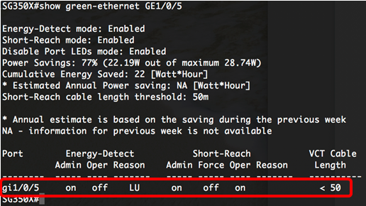
Step 1. In the Privileged EXEC mode, verify the configured Green Ethernet settings on the interface by entering the following:

Note: In this example, show green-ethernet GE1/0/5 command is used.

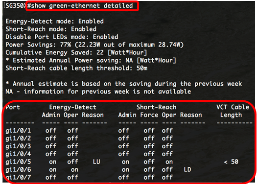
Step 2. (Optional) To check the port settings of all interfaces, enter the following:


Step 3. (Optional) To save the configured settings to the startup configuration file, enter the following:


Step 4. (Optional) Press Y for Yes or N for No on your keyboard once the Overwrite file [startup-config]… prompt appears.

Note: In this example, Y is pressed.
You should now have successfully verified the Green Ethernet settings of the ports on your switch through the CLI.
Revision History
| Revision | Publish Date | Comments |
|---|---|---|
1.0 |
13-Dec-2018 |
Initial Release |
 Feedback