View the Link Layer Discovery Protocol (LLDP) Local Information on a Switch
Available Languages
Objective
Link Layer Discovery Protocol (LLDP) Media Endpoint Discovery (MED) provides additional capabilities to support media endpoint devices such as to enable the advertisement of network policies for applications like voice or video, device location discovery, and troubleshooting information. LLDP and Cisco Discovery Protocol (CDP) are both similar protocols, and the difference is that LLDP facilitates vendor interoperability and CDP is Cisco proprietary. LLDP can be used in scenarios where the user needs to work between devices which are not Cisco proprietary and devices which are Cisco proprietary.
The LLDP protocol is useful to network administrators for troubleshooting purposes. The switch gives all the information about the current LLDP status of ports. The network administrator can use this information to fix connectivity problems within the network.
Note: To know how to configure LLDP properties on a switch, click here for instructions.
This article provides instructions on how to view the LLDP local information on your switch.
Applicable Devices
- Sx250 Series
- Sx300 Series
- Sx350 Series
- SG350X Series
- Sx500 Series
- Sx550X Series
Software Version
- 1.4.7.05 — Sx300, Sx500
- 2.2.8.04 — Sx250, Sx350, SG350X, Sx550X
View LLDP Local Information
Step 1. Choose Administration > Discover – LLDP > LLDP Local Information.
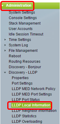
Note: The available menu options may vary depending on the device model. In this example, SG350X-48MP is used.
Step 2. Choose the desired interface type from the Interface drop-down lists.

Note: In this example, Port GE10 of Unit 1 is chosen.
Global
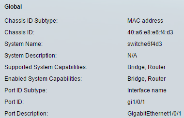
- Chassis ID Subtype — Type of chassis ID. (For example, the MAC address.)
- Chassis ID — Identifier of chassis. Where the chassis ID subtype is a MAC address, the MAC address of the device appears.
- System Name — Name of device.
- System Description — Description of the device (in alpha-numeric format).
- Supported System Capabilities — Primary functions of the device, such as Bridge, WLAN AP, or Router.
- Enabled System Capabilities — Primary enabled function(s) of the device.
- Port ID Subtype — Type of the port identifier that is shown.
- Port ID — Identifier of port.
- Port Description — Information about the port, including manufacturer, product name and hardware/software version.
Management Address
Displays the table of addresses of the local LLDP agent. Other remote managers can use this address to obtain information related to the local device. The address consists of the following elements:
On Sx250, Sx350, SG350X, and Sx550X Series switches:

- IPv4 Address — The IPv4 address of the switch.
- IPv6 Global Address — The IPv6 global address of the switch.
- IPv6 Link Local Address — The IPv6 link local address of the switch.
On Sx200, Sx300, and Sx500 Series switches:
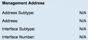
- Address Subtype — Type of management IP address that is listed in the Management Address field; for example, IPv4.
- Address — Returned address most appropriate for management use.
- Interface Subtype — Numbering method used for defining the interface number.
- Interface Number — Specific interface associated with this management address.
MAC/PHY Details
Note: This area is only available on Sx250, Sx350, SG350X, and Sx550X Series switches.
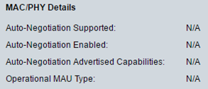
- Auto-Negotiation Supported — Port speed auto-negotiation support status.
- Auto-Negotiation Enabled — Port speed auto-negotiation active status.
- Auto-Negotiation Advertised Capabilities — Port speed auto-negotiation capabilities; for example, 1000BASE-T half duplex mode, 100BASE-TX full duplex mode.
- Operational MAU Type — Medium Attachment Unit (MAU) type. The MAU performs physical layer functions, including digital data conversion from the Ethernet interfaces' collision detection and bit injection into the network; for example, 100BASE-TX full duplex mode.
802.3 Details

- 802.3 Maximum Frame Size — The maximum supported IEEE 802.3 frame size.
802.3 Link Aggregation

- Aggregation Capability — Indicates if the interface can be aggregated.
- Aggregation Status — Indicates if the interface is aggregated.
- Aggregation Port ID — Advertised aggregated interface ID.
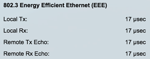
802.3 Energy Efficient Ethernet (EEE)
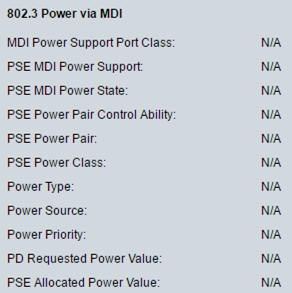
- MDI Power Support Port Class — Advertised power support port class.
- PSE MDI Power Support — Indicates if MDI power is supported on the port.
- PSE MDI Power State — Indicates if MDI power is enabled on the port.
- PSE Power Pair Control Ability — Indicates if power pair control is supported on the port.
- PSE Power Pair — Power pair control type supported on the port.
- PSE Power Class — Advertised power class of the port.
- Power Type — Type of pod device connected to the port.
- Power Source — Port power source.
- Power Priority — Port power priority.
- PD Requested Power Value — Amount of power allocated by the PSE to the PD.
- PSE Allocated Power Value — Amount of power allocated to the sourcing equipment (PSE).
802.3 Power via MDI
Note: This area is only available on Sx250, Sx350, SG350X, and Sx550X Series switches.
- Local Tx — Indicates the time (in micro seconds) that the transmitting link partner waits before it starts transmitting data after leaving Low Power Idle (LPI mode).
- Local Rx — Indicates the time (in micro seconds) that the receiving link partner requests that the transmitting link partner waits before transmission of data following LPI mode:
- Remote Tx Echo — Indicates the reflection of the local link partner of the remote Tx value of the link partner.
- Remote Rx Echo — Indicates the reflection of the local link partner of the remote Rx value of the link partner.
4-Wire Power via MDI
Note: This area is only available on Sx250, Sx350, SG350X, and Sx550X Series switches.

- 4-Pair PoE Supported — Indicates system and port support enabling the 4-pair wire (true only for specific ports that have this HW ability).
- Spare Pair Detection/Classification Required — Indicates that the 4-pair wire is needed.
- PD Spare Pair Desired State — Indicates a pod device requesting to enable the 4-pair ability.
- PD Spare Pair Operational State — Indicates whether the 4-pair ability is enabled or disabled.
MED Details
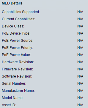
- Capabilities Supported — MED capabilities supported on the port.
- Current Capabilities — MED capabilities enabled on the port.
- Device Class — LLDP-MED endpoint device class. The possible device classes are:
- Endpoint Class 1 — Generic endpoint class, offering basic LLDP services.
- Endpoint Class 2 — Media endpoint class, offering media streaming capabilities, as well as all Class 1 features.
- Endpoint Class 3 — Communications device class, offering all Class 1 and Class 2 features plus location, 911, Layer 2 device support, and device information management capabilities.
- PoE Device Type — Port PoE type; for example, PD.
- PoE Power Source — Port power source.
- PoE Power Priority — Port power priority.
- PoE Power Value — Port power value.
- Hardware Revision — Hardware version.
- Firmware Revision — Firmware version.
- Software Revision — Software version.
- Serial Number — Device serial number.
- Manufacturer Name — Device manufacturer name.
- Model Name — Device model name.
- Asset ID — Asset ID.
Local Information

- Civic — Street address.
- Coordinates — Map coordinates: latitude, longitude, and altitude.
- ECS ELIN — Emergency Call Service (ECS) Emergency Location Identification Number (ELIN).
Network Policy Table

- Application Type — Network policy application type; for example, Voice.
- VLAN ID — VLAN ID for which the network policy is defined.
- VLAN Type — VLAN type for which the network policy is defined. The possible field values are:
- Tagged — Indicates the network policy is defined for tagged VLANs.
- Untagged — Indicates the network policy is defined for untagged VLANs.
- User Priority — Network policy user priority.
- DSCP — Network policy DSCP.
Step 3. (Optional) Click the LLDP Port Status Table button to view the LLDP Port Status Global Information. To learn more about this feature, click here for instructions.

You should now have viewed the local information of a port on your switch.
Revision History
| Revision | Publish Date | Comments |
|---|---|---|
1.0 |
10-Dec-2018 |
Initial Release |
 Feedback