Configure VRRP Virtual Routers on an SG550XG Switch
Available Languages
Introduction
If you are unfamiliar with the terms used in this article, check out Cisco Business: Glossary of New Terms.
Virtual Router Redundancy Protocol (VRRP) is an election and redundancy protocol that dynamically assigns the responsibility of a virtual router to one of the physical routers on a Local Area Network (LAN). This increases the availability and reliability of routing paths in the network.
In VRRP, one physical router in a virtual router is elected as the active router, with the other physical router of the same virtual router acting as standbys in case the active router fails. The physical routers are referred as VRRP routers.
The default gateway of a participating host is assigned to the virtual router instead of a physical router. If the physical router that is routing packets on behalf of the virtual router fails, another physical router is selected to automatically replace it. The physical router that is forwarding packets at any given time is called the active router router.
VRRP also enables load sharing of traffic. Traffic can be shared equitably among available routers by configuring VRRP in such a way that traffic to and from LAN clients are shared by multiple routers.
The benefits of VRRP are as follows:
- Redundancy — Enables you to configure multiple routers as the default gateway router, which reduces the possibility of a single point of failure in a network.
- Load sharing — Allows traffic to and from LAN clients to be shared by multiple routers. The traffic load is shared more equitably among available routers.
- Multiple VRRP groups — Supports up to 255 VRRP groups on a router physical interface if the platform supports multiple MAC addresses. Multiple VRRP groups enable you to implement redundancy and load sharing in your LAN topology.
- Multiple IP addresses — Allows you to manage multiple IP addresses, including secondary IP addresses. If you have multiple subnets configured on an Ethernet interface, you can configure VRRP on each subnet.
- Preemption — Enables you to preempt a standby router that has taken over for a failing active router with a higher priority standby router that has become available.
- Advertisement protocol — Uses a dedicated Internet Assigned Numbers Authority (IANA) standard multicast address (224.0.0.18) for VRRP advertisements. This addressing scheme minimizes the number of routers that must service the multicasts and allows test equipment to accurately identify VRRP packets on a segment. IANA has assigned the IP protocol number 112 to VRRP.
- VRRP tracking — Ensures that the best VRRP router is the active router for the group by altering VRRP priorities based on interface states.
The image below shows a basic VRRP topology. In this example, Routers A, B, and C form a VRRP group. The IP address of the group is the same address that was configured for the Ethernet interface of Router A (192.168.10.1).
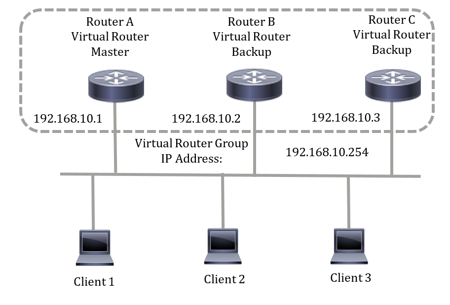
Because the virtual IP address uses the IP address of the physical Ethernet interface of Router A, Router A is the active router (also known as the IP address owner). As the active router, Router A owns the virtual IP address of the VRRP group and forwards packets sent to this IP address. Clients 1 through 3 are configured with the default gateway IP address of 192.168.10.254.
Note: The configuration can be made so that the active virtual router, not the IP address owner, can still respond or process the packets. An example is ping.
Routers B and C function as virtual router standbys. If the virtual active router fails, the router configured with the higher priority becomes the virtual active router and provides service to the LAN hosts with minimal interruption.
When Router A recovers, it becomes the virtual active router again. During the period that the active is recovering, both actives forwards packets and as a result, there is some duplication (regular behavior) but no interruption.
In this topology, two virtual routers are configured. For virtual router 1, Router A is the owner of IP address 192.168.10.1 and is the virtual active router, and Router B is the virtual router standby to Router A. Clients 1 and 2 are configured with the default gateway IP address of 192.168.10.254.
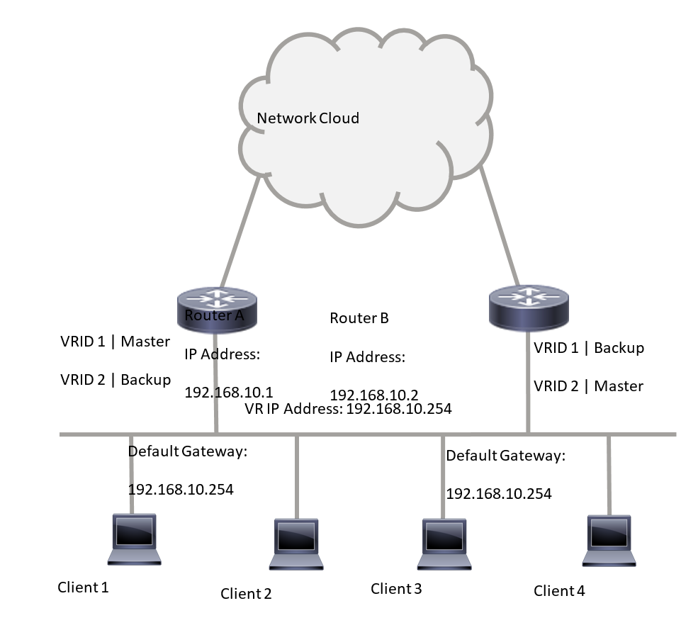
For virtual router 2, Router B is the owner of IP address 192.168.10.2 and virtual active router, and Router A is the virtual router standby to Router B. Clients 3 and 4 are configured with the default gateway IP address of 192.168.10.254.
Before configuring the VRRP settings on the switch, follow these guidelines:
- Configure VLANs. To learn how to configure VLAN on your switch, click here.
- Configure IP SLA Tracking on the switch. To learn more about this feature, click here.
Objective
A virtual router must be assigned with a unique virtual router identifier (VRID) among all the virtual routers on the same LAN. All VRRP routers supporting the same virtual router must be configured with all the information relating to the virtual router including its VRID. Virtual routers should be enabled on the device only when IP routing is also enabled on the device.
This article provides instructions on how to configure VRRP settings on your switch.
Applicable Devices
- SG550XG Series
Software Version
- 2.3.0.130
Configure VRRP Virtual Routers on a Switch
Step 1. Log in to the web-based utility of your switch then choose Advanced in the Display Mode drop-down list.
Note: The available menu options may vary depending on the device model. In this example, SG550XG-24T is used.

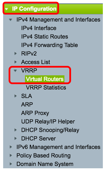
Step 2. Choose IP Configuration > VRRP > Virtual Routers.
Step 3. Click Add to add a new interface.

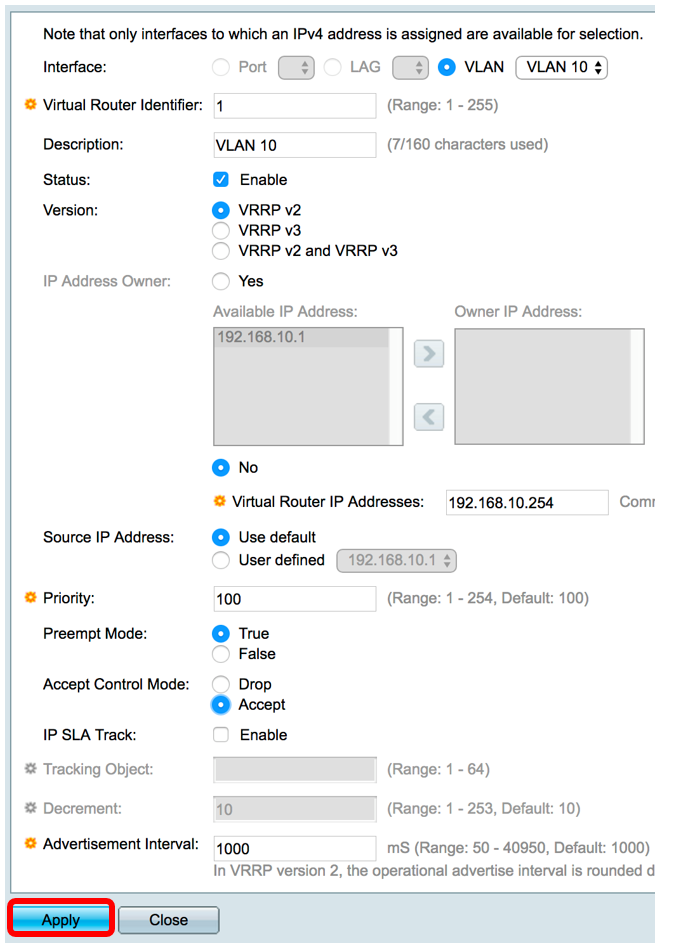
Step 4. Choose an interface from the Interface area. In this example, VLAN 10 is chosen.

Step 5. Enter a virtual router identifier in the Virtual Router Identifier field. The range is from one to 255.

Note: In this example, 1 is used.
Step 6. (Optional) Enter a description in the Description field.

Note: In this example, VLAN 10 is entered.
Step 7. Check the Enable Status check box to enable VRRP on the switch.

Step 8. Choose the VRRP version to be used. The options are:
- VRRP v2 — VRRPv2 specified by RFC3768 is supported. Received VRRPv3 messages are dropped by the VRRP virtual router. Only VRRPv2 advertisements are sent.
- VRRP v3 — VRRPv3 specified by RFC5798 is supported without VRRPv2 support (8.4, RFC5798). Received VRRPv2 messages are dropped by the VRRP virtual router. Only VRRPv3 advertisements are sent.
- VRRP v2 and VRRP v3 — VRRPv3 specified by RFC5798 is supported with VRRPv2 support (8.4, RFC5798). Received VRRPv2 messages are treated by the VRRP virtual router. VRRPv3 and VRRPv2 advertisements are sent.

Note: In this example, VRRP v2 is chosen.
Step 9. Click an option from the IP Address Owner area. The options are:
- Yes — If Yes is chosen, this indicates that the IP address of the device is the IP address of the virtual router. Choose the IP addresses of the owner from the Available IP Address list and move it to the Owner IP Address list.
- No — If No is chosen, you must enter the address or addresses of the virtual router in the Virtual Router IP Addresses field. If multiple IP addresses are added here, separate them as follows: 1.1.1.1, 2.2.2.2.
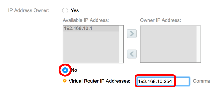
Note: In this example, No is chosen and the IP address entered is 192.168.10.254. This indicates the IP address on the virtual router.
Step 10. Choose the IP address to be used in VRRP messages. The default source IP address is the lowest of the IP addresses defined on the interface. If User defined is chosen, choose the IP address accordingly.

Note: In this example, Use default is chosen.
Step 11. If this device is the owner, this field gets the value 255, and this value cannot be changed. If not, enter the priority of this device, based on its ability to function as the active router. The default value for a non-owner device is 100.
Note: The VRRP router priority depends on the following: If the VRRP router is the owner, its priority is 255 (the highest). If it is not an owner, the priority is manually configured (always less than 255).

Note: In this example, 100 is used. If you are configuring a standby virtual router, enter a lesser priority.
Step 12. In the Preempt Mode area, choose from the following options:
- True — When a VRRP router is configured with higher priority than the current active is up, it replaces the current active.
- False — Even if a VRRP router with a higher priority than the current active is up, it does not replace the current active. Only the original active (when it becomes available) replaces the standby.

Note: In this example, True is chosen.
Step 13. In the Accept Control Mode area, choose from the following options:
- Accept — The virtual router in active state will accept packets addressed to the IP address of the virtual router as its own even if it is not the address owner.
- Drop — The virtual router in active state will drop packets addressed to the virtual router IP address if it is not the address owner.

Note: In this example, Accept is chosen.
Step 14. (Optional) Check the Enable IP SLA Track check box to enable tracking of connectivity from the router to the next hop of the default route. To learn more about this feature, click here.

Note: In this example, IP SLA Track is disabled.
Step 15. (Optional) If IP SLA Track is enabled, enter the number of the SLA track that verifies the connectivity in the Tracking Object field. This value was entered in the SLA Tracks page. You can use one up to 64.

Note: In this example, 1 is used.
Step 16. (Optional) IP SLA Track is enabled, enter the decrement value in the Decrement field. If the track object state is down, the VRRP priority of the router is decremented by this value. You can use one to 253 and the default is 10.
Note: In this example, 10 is used.

Step 17. Enter how frequently advertisement packets are sent in the Advertisement Interval field.

Note: In this example, 1000 is used.
Step 18. Click Apply then click Close.
Step 19. (Optional) Click Save to save the settings to the startup configuration file.

Note: The active/standby Status area of the IPv4 VRRP Virtual Router Table should display the status of the virtual router that you have configured. If you intend to configure a standby virtual router, the status should display as standby.

You should now have successfully configured the VRRP virtual router settings on your SG550XG switch.
Revision History
| Revision | Publish Date | Comments |
|---|---|---|
1.0 |
13-Dec-2018 |
Initial Release |
 Feedback