Configuring Link Aggregation Groups on the SG350XG and SG550XG
Available Languages
Objective
A Link Aggregation Group (LAG) is a collection of network connections that have been combined in parallel into one logical connection. Creating a LAG can allow for redundancy: if one link in the LAG fails, other links can be used as backups. LAGs can also greatly increase throughput by using all of its links to transmit data simultaneously.
Here's how it works: Link Aggregation Control Protocol (LACP) is a part of IEEE specification (802.3az) that can control the bundling of several physical ports together to form a single logical channel (LAG). Traffic load balancing over the active member ports of a LAG is managed by a hash-based distribution function that distributes unicast and multicast traffic based on Layer 2 or Layer 3 packet header information. LACP helps to form one single LAG by bundling many physical ports. It is also responsible for bandwidth multiplication, increase in port flexibility, and in providing redundancy on links between any 2 devices. Additionally this helps in changing the LAG speed, advertisement, flow control, and also protection which can be easily identified in LAG settings table.
The objective of this document is to show you how to configure LAGs on the SG350XG and SG550XG.
Applicable Devices
- SG350XG
- SG550XG
Software Version
- 2.0.0.73
LAG Management
Step 1. Log in to the web configuration utility and choose Port Management > Link Aggregation > LAG Management. The LAG Management page opens.
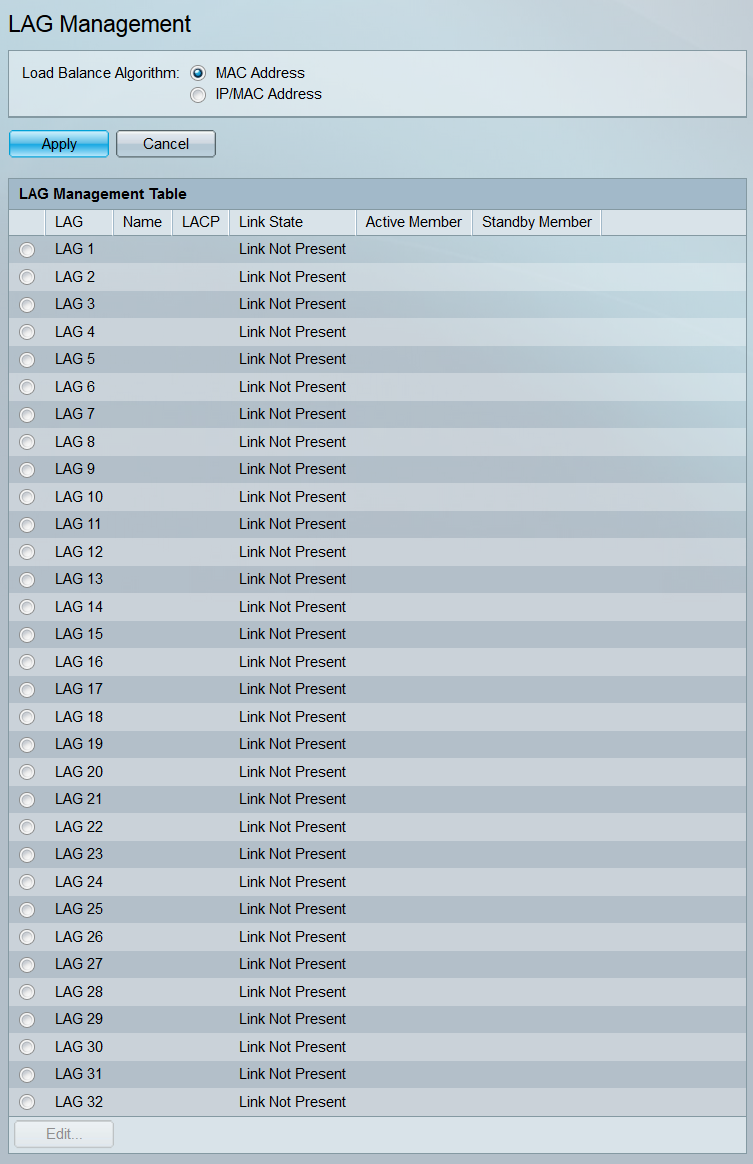
Note: The above screenshot is taken from the SG550XG, which has 32 different LAGs. The SG350XG only has 8 LAGs.
Step 2. In the Load Balance Algorithm field, choose a radio button to determine how the switch will handle load balancing on each LAG. Load balancing is used to send data across all links in a LAG, increasing throughput. Using the MAC Address has been found to be more effective in some networks.

The options are:
- MAC Address – Perform load balancing by using the source and destination MAC address on all packets.
- IP/MAC Address – Perform load balancing by using the source and destination IP address on IP packets, and the source and destination MAC address on all non-IP packets.
Step 3. Click Apply. The load balancing setting is saved to the running configuration file.

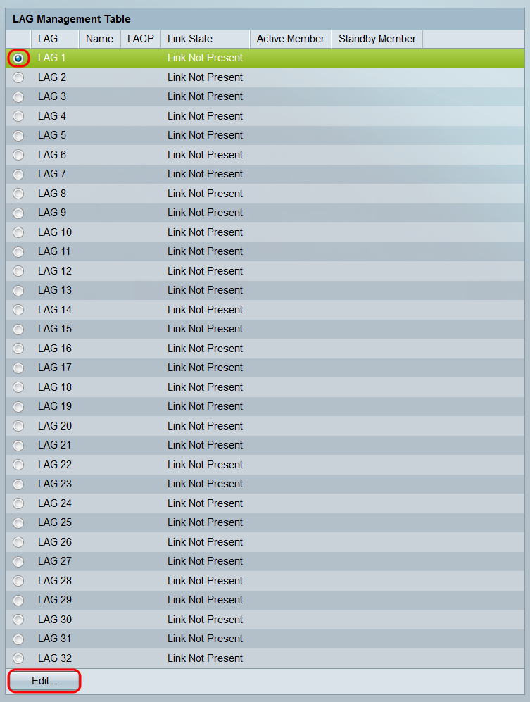
Step 4. The LAG Management Table displays information on all of the LAGs currently configured on the switch. Select a LAG’s radio button and click Edit… to edit its settings in the Edit LAG Membership window that appears.
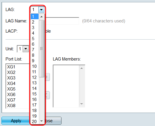
Step 5. In the LAG drop-down list, select the LAG whose settings you want to configure. The LAG you selected in the LAG Management Table will automatically be selected here. This field can be used for switching between LAGs and configuring their settings without returning to the LAG Management page.
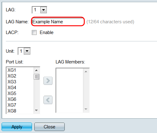
Step 6. In the LAG Name field, enter in a name or description of the LAG. This name will not impact the operation of the LAG, as it is only for easy identification.
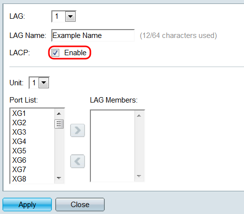
Step 7. In the LACP field, check the Enable checkbox to enable the Link Aggregation Control Protocol (LACP) for the LAG. The switch uses LACP to communicate with the other connected device (that also uses LACP) and coordinate LAG information, creating a dynamic LAG. Once ports have been added to a LAG, this field becomes unavailable; removing all ports from a LAG will allow this setting to be available again.
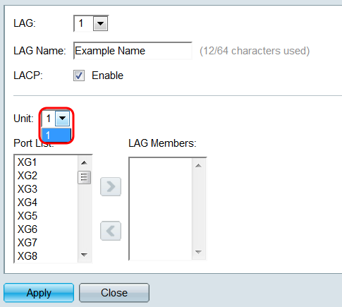
Step 8. In the Unit drop-down list, select the switch in the stack that contains the ports you want to add to the LAG. If the switch is not part of a stack, only 1 will be available.
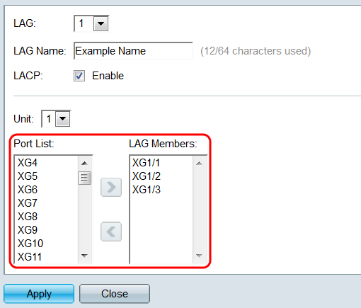
Step 9. Using the arrow buttons, select a port from the Port List and move it to the LAG Members area, or vice versa.
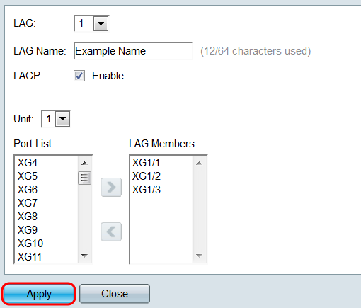
Step 10. Click Apply. The LAG settings are saved to the running configuration. Select another LAG to configure in the LAG field, or click Close to return to the LAG Management page.
LAG Settings
Step 1. Log in to the web configuration utility and choose Port Management > Link Aggregation > LAG Settings. The LAG Settings page opens.
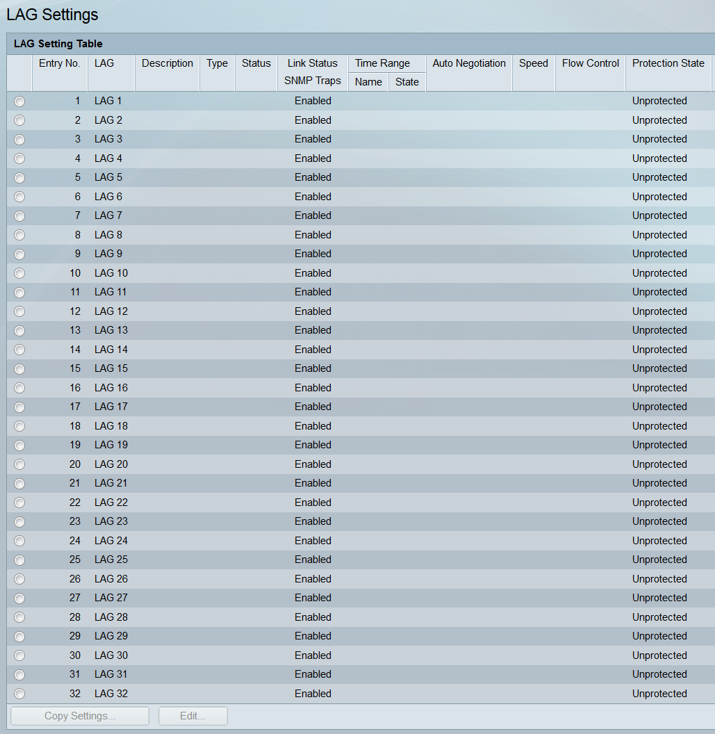
Step 2. The LAG Setting Table displays information on all LAGs currently configured on the switch. Select a LAG’s radio button and click Edit… to edit its settings in the Edit LAG Settings page.
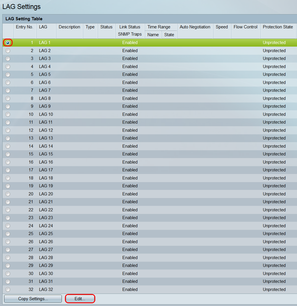
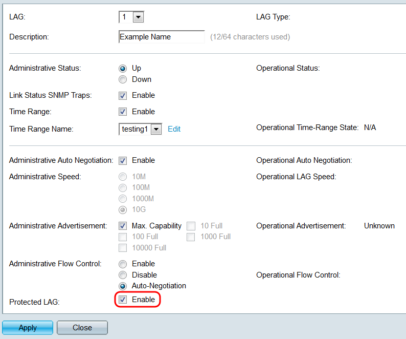
Step 3. In the LAG drop-down list, select the LAG whose settings you want to configure. The LAG you selected in the LAG Setting Table will automatically be selected here. This field can be used for switching between LAGs and configuring their settings without returning to the LAG Settings page. The LAG Type field displays the port type that makes up the LAG.
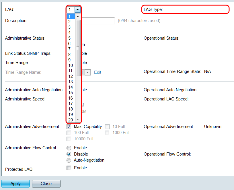
Step 4. In the Description field, enter in a name or comment for the LAG. This does not impact operation of the LAG, as it is only for identification purposes.
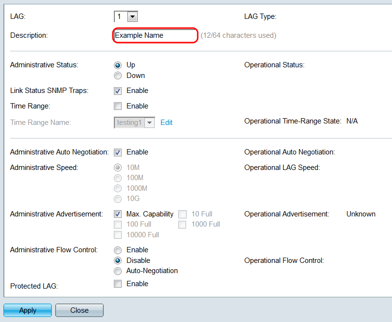
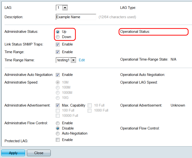
Step 5. In the Administrative Status field, select either the Up or Down radio button to determine if the LAG will be up (operational) or down (non-operational). The Operational Status field displays whether the LAG is currently up or down. If the current display mode is Basic, skip to Step 9.
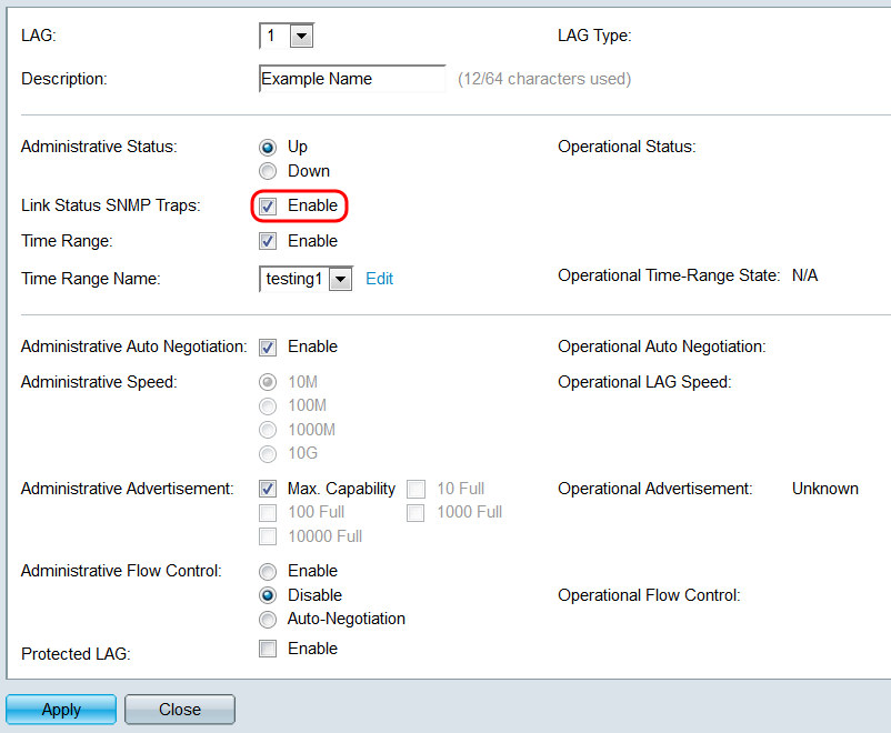
Step 6. In the Link Status SNMP Traps field, check the Enable checkbox to have the switch generate SNMP traps that notify of changes to the link status of the ports in the LAG.
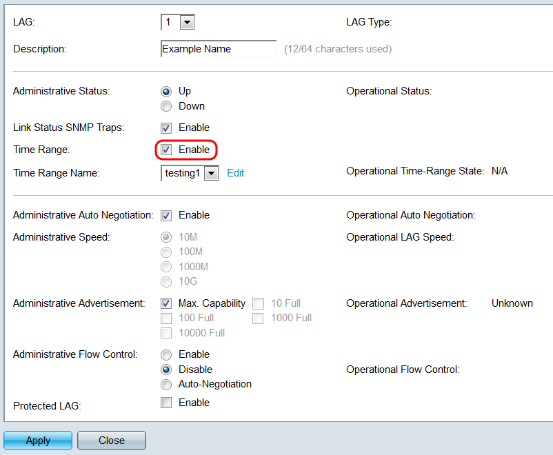
Step 7. In the Time Range field, check the Enable checkbox to have the LAG only be up during a preconfigured time range. When outside this time range, the LAG will be shut down. If there are no time range profiles available, this field is unavailable.
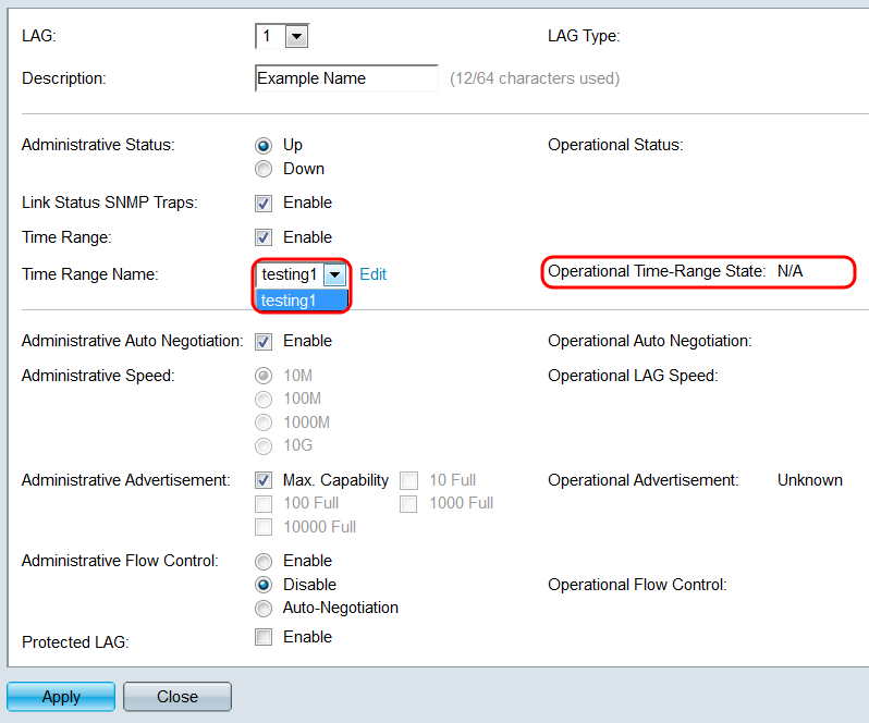
Step 8. In the Time Range Name drop-down list, select a time range profile to apply to the LAG. If there are no time range profiles defined, or if you wish to make changes to an existing one, click Edit to go to the Time Range page. The Operational Time-Range State field displays whether the time range is currently active or inactive. For more information about time ranges, please refer to the article Setting Up a Time Range on the SG550XG and SG350XG.
Step 9. In the Administrative Auto Negotiation field, check the Enable checkbox to turn on auto-negotiation for the LAG. This feature lets a LAG automatically transmit its transmission speed, duplex mode, and Flow Control abilities to the LAG partner. If this feature is enabled, skip to Step 11. The Operational Auto Negotiation field displays the current auto-negotiation status of the LAG.
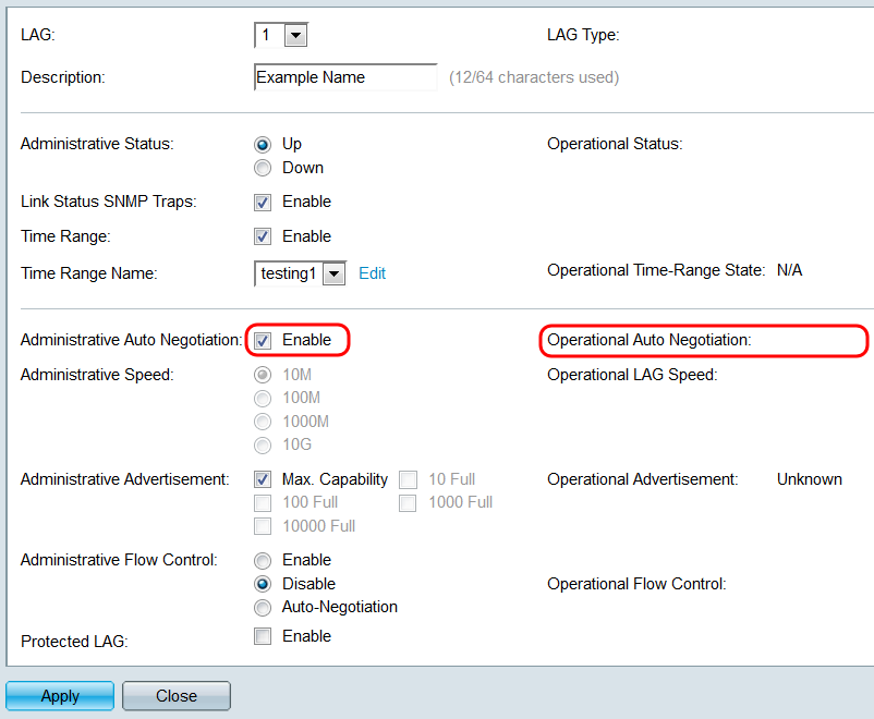
Step 10. If auto-negotiation is not enabled, the Administrative Speed field becomes available. Select a radio button to determine the speed of the LAG. The Operational LAG Speed field displays the current speed of the LAG.
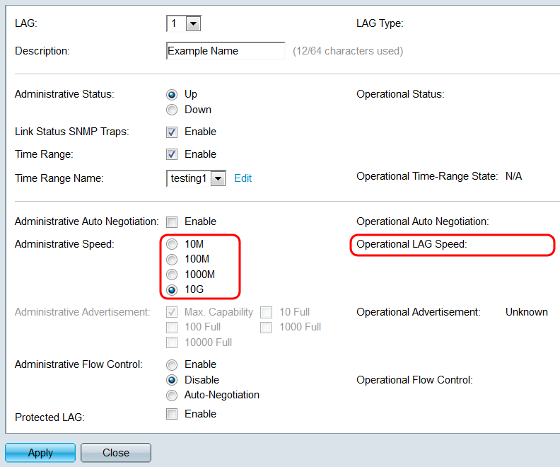
The options are:
- 10M – The LAG operates at a speed of 10 Mbps.
- 100M – The LAG operates at a speed of 100 Mbps.
- 1000M – The LAG operates at a speed of 1000 Mbps.
- 10G – The LAG operates at a speed of 10 Gbps.
Step 11. If auto-negotiation is enabled, the Administrative Advertisement field will be available. Check the appropriate checkboxes to indicate which capabilities are advertised during auto-negotiation. The Operational Advertisement field displays the capabilities currently being advertised by the LAG.
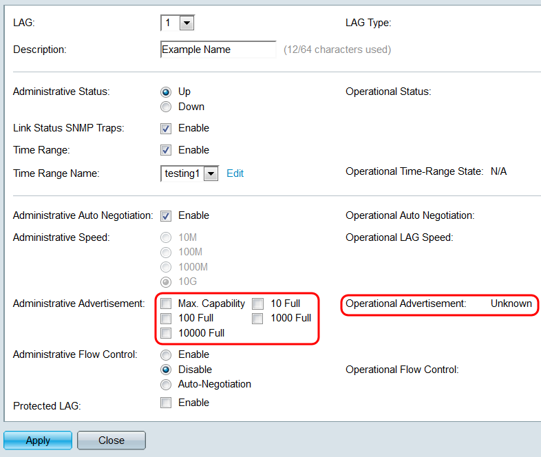
The options are:
- Max Capability – All speeds and duplex mode settings are accepted. This is checked by default. No other checkboxes can be selected if this option is selected.
- 10 Full – 10 Mbps speed and full duplex mode.
- 100 Full – 100 Mbps speed and full duplex mode.
- 1000 Full – 1000 Mbps speed and full duplex mode.
- 10000 Full – 10000 Mbps speed and full duplex mode.
Step 12. In the Administrative Flow Control field, select a radio button to Enable or Disable 802.3x flow control. You can also choose to enable Auto-Negotiation of flow control. Flow control is a protocol that the switch can use to halt the transmission of the remote LAG if the network becomes overwhelmed. The Operational Flow Control field displays the current flow control status of the LAG.
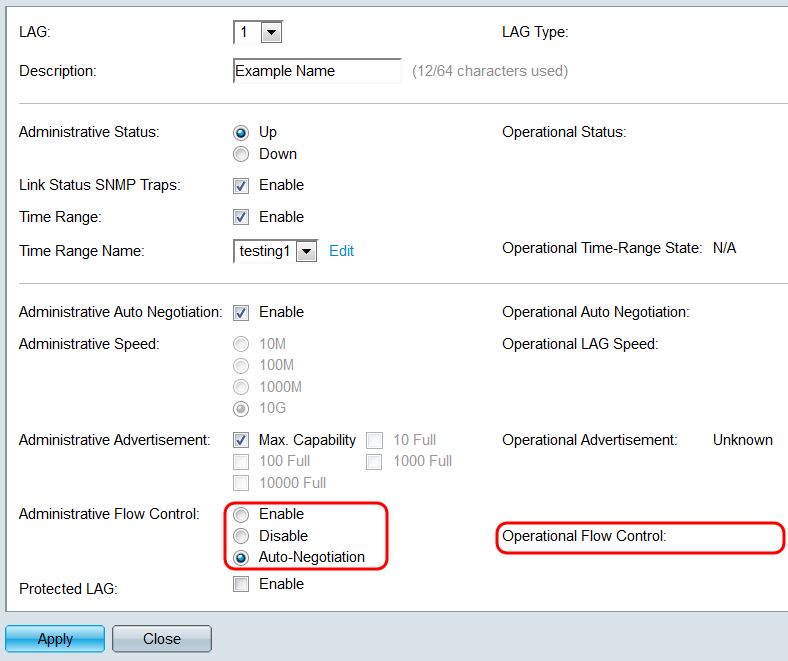
Step 13. In the Protected LAG field, check the Enable checkbox to make the LAG a protected LAG. A protected LAG provides layer 2 isolation between interfaces that share the same VLAN.
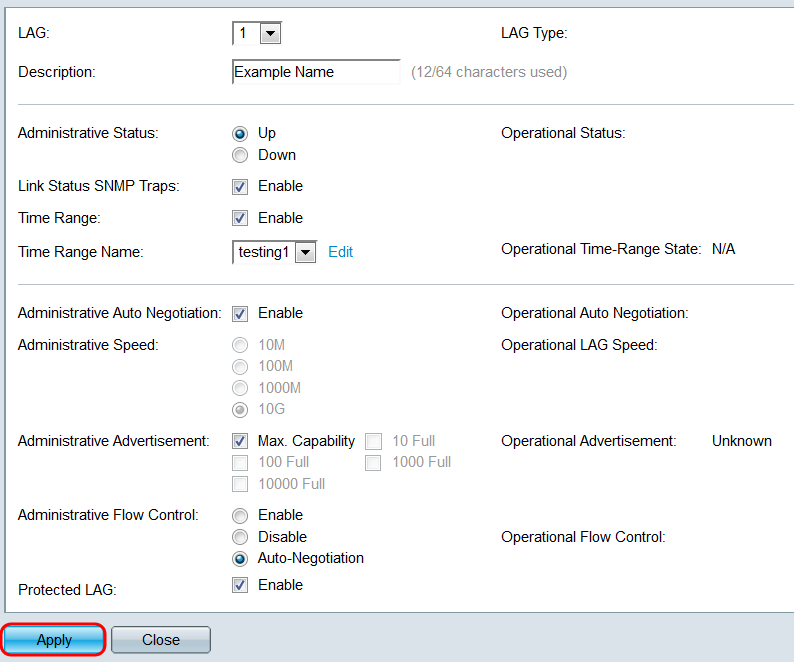
Step 14. Click Apply. The settings are saved to the running configuration file. Select another LAG to configure from the LAG field, or click Close to return to the LAG Settings page.
Step 15. If you want to quickly copy a LAG’s settings to another LAG, click its radio button, then the Copy Settings… button. The Copy Settings window appears.
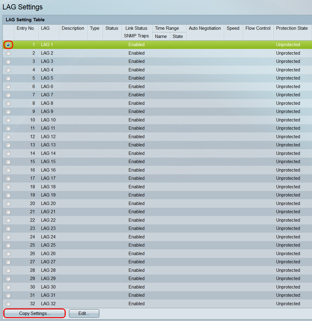
Step 16. In the text field, enter the LAG or range of LAGs that you want to copy the selected LAG’s settings to, and click Apply.
