Configure Multiple Spanning Tree Protocol (MSTP) on a Switch
Available Languages
Objective
Spanning Tree Protocol (STP) is a network protocol that ensures a loop-free topology for a bridged Local Area Network (LAN). Multiple Spanning Tree Protocol (MSTP) is a protocol that creates multiple spanning trees (instances) for each Virtual LAN (VLAN) on a single physical network. This allows for each VLAN to have a configured root bridge and forwarding topology. This reduces the number of Bridge Protocol Data Units (BPDUs) across the network and reduces stress on the Central Processing Units (CPUs) of the network devices.
MSTP is an extension to Rapid Spanning Tree Protocol (RSTP). MSTP further develops the usefulness of VLANs. MSTP configures a separate spanning tree for each VLAN group and blocks all but one possible alternate path within each spanning tree. MSTP allows formation of Multiple Spanning Tree (MST) regions that can run multiple MST instances (MSTI). Each VLAN can be mapped to an MSTI and for the devices to be in the same region they must have the same VLANs to MSTIs mapping.
This article provides instructions on how to configure MSTP on a switch.
Applicable Devices
-
Sx250 Series
-
Sx300 Series
-
Sx350 Series
-
SG350X Series
-
Sx550X Series
Software Version
- 1.4.5.02 – Sx300 Series
- 2.2.0.66 – Sx250 Series, Sx350 Series, SG350X Series, Sx550X Series
Configure MSTP on the Switch
Enable MSTP
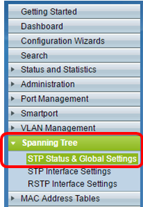
Step 1. Log in to the web-based utility then choose Spanning Tree > STP Status & Global Settings.
Important: To fully utilize the available features and functions of the switch, change to Advanced mode by clicking Advanced from the Display Mode drop-down list in the upper-right corner of the page.

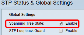
Step 2. In the Global Settings area, check the Spanning Tree State check box to enable STP on the switch.
Note: Spanning Tree State is enabled by default. MSTP can be configured before STP is enabled on the switch.
Step 3. Click the Multiple STP radio button in the STP Operation Mode area to configure the STP mode as MSTP.
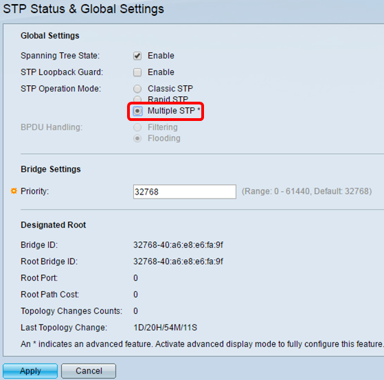
Step 4. Click Apply.
You should now have enabled MSTP on your switch.
Configure MSTP Properties
The MSTP Properties page is used to define what region the switch is in. For devices to be in the same region, they must have the same region name and revision value.
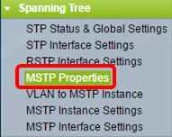
Step 1. Choose Spanning Tree > MSTP Properties from the menu.
Step 2. Enter a name for the MSTP region in the Region Name field. The region name defines the logical boundary of the network. All switches in an MSTP region must have the same configured region name.
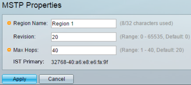
Step 3. Enter a revision number in the Revision field. This is a logical number that signifies a revision for the MSTP Configuration. All switches in an MSTP region must have the same revision number.
Step 4. Enter the maximum number of hops in the Max Hops field. Max Hops specifies the lifetime of BPDUs in hop counts. When a bridge receives a BPDU, it decrements the hop count by one and resends the BPDU with the new hop count. Once a bridge receives a BPDU with a hop count of zero, the BPDU is discarded.
Note: The IST Primary field displays the bridge priority and MAC address of the active switch of the region.
If you are unfamiliar with the terms used, check out Cisco Business: Glossary of New Terms.
Step 5. Click Apply.
Configure VLAN to MSTP Instance
The VLAN to MSTP Instance page is used to map VLANs to MST Instances. For devices to be in the same region, they must have identical mappings of VLANs to MST Instances. Multiple VLANs can be mapped to single MSTI, however a VLAN can have only a single MSTI. If a VLAN is not mapped to one of the MST Instances, the switch automatically maps the VLAN to the Core and Internal Spanning Tree (CIST). The CIST instance ID is instance ID 0.
Step 1. Choose Spanning Tree > VLAN to MSTP Instance from the menu.
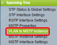
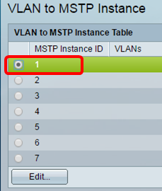
Step 2. Click the radio button that corresponds to the desired MSTP Instance that you want to configure then click Edit.
Step 3. (Optional) From the MSTP Instance ID drop-down list, choose an MSTP Instance to edit.
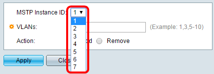
Step 4. Enter the VLANs that are to be mapped to the MSTI. VLANs can be mapped individually (separated by commas) or as a range (through the use of a hyphen).

Step 5. Click the radio button that corresponds to the desired action in the Action area.
-
Add — Add the VLAN(s) to the MSTI.
-
Remove — Remove the VLAN(s) from the MSTI.
Step 6. Click Apply.
Configure MSTP Instance Settings
The MSTP Instance Settings page is used to define specifications for each MST instance.
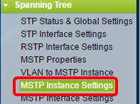
Step 1. Choose Spanning Tree > MSTP Instance Settings from the menu of the web-based utility.
Step 2. From the Instance ID drop-down list, choose an Instance to be configured.
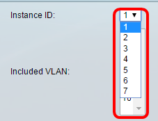
Note: The Included VLAN list displays the VLANs that are mapped to the instance.
Step 3. Enter the priority value of the switch in the Bridge Priority field. The switch with the highest priority (lowest priority value) will become the root bridge.
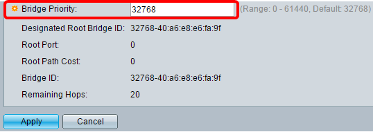
The field displays information about the MSTI.
-
Designated Root Bridge ID — The bridge priority and MAC address of the root bridge for the specified instance.
-
Root Port — The root port of the specified instance. The root port is the single port that the switch uses to reach the root bridge. This is decided based on the port that has the least path cost to the root bridge. If this value is zero, the switch is the root bridge.
-
Root Path Cost — The root path cost of the switch for this MST instance. Path cost is defined by the speed of the link between the switch and the next device in the network. The root path cost is the cumulative total of the path costs from the switch to the root bridge. If this value is zero, the switch is the root bridge.
-
Bridge ID — The bridge priority and MAC address of the switch for the specified instance.
-
Remaining Hops — The number of hops until the next destination.
Configure MSTP Interface Settings
The MSTP Interface settings page is used to configure MSTP settings per port for a selected MSTP instance.
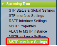
Step 1. Choose Spanning Tree > MSTP Interface Settings from the web-based utility menu.
Step 2. From the Instance equals to drop-down list, click an instance to be configured.
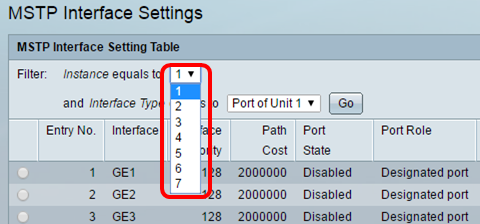
Step 3. From the Interface Type equal to drop-down list, click either Port or LAG then click Go.

Step 4. Click the radio button that corresponds to the desired interface you want to configure then click Edit.

Step 5. (Optional) From the Instance ID drop-down list, choose the instance to be configured.
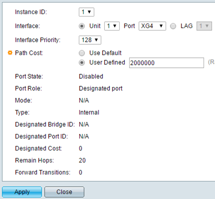
Step 6. (Optional) Click the radio button that corresponds to the desired Interface to be configured.
-
Port — From the Port drop-down list, choose the port to configure. This will only affect the single port chosen.
-
LAG — From the LAG drop-down list, choose the LAG to configure. This will affect the group of ports defined in the LAG configuration.
Step 7. From the Interface Priority drop-down list, choose the priority of the interface for the defined interface. The priority value determines the port choice when a bridge has two ports connected in a loop. The lower the value, the higher the priority the port will have on the bridge.
Step 8. Click the radio button that corresponds to the desired path cost in the Path Cost area. This is the path cost of the port which is added to the root path cost. The path cost is defined by the speed of the link between the switch and the next device in the network. The root path cost is the cumulative total of the path costs from the switch to the root bridge.
-
Use Default — Use the default cost generated by the system.
-
User Defined — Enter a value for the path cost.
The following field displays information of the interface.
-
Port State — Current state of the specified port.
– Disabled — STP is disabled on the port. The port forwards traffic and learns MAC addresses.
– Blocking — The port is blocked. This means the port is not allowed to forward traffic or learn MAC addresses, however the port can forward BPDU packets.
– Listening — The port is in listening mode. This means the port is not allowed to forward traffic and cannot learn MAC addresses.
– Learning — The port is in learning mode. This means the port is not allowed to forward traffic but it is allowed to learn new MAC addresses.
– Forwarding — The port is in forwarding mode. This means the port is allowed to forward traffic and can learn new MAC addresses.
-
Port Role — The role of the port or LAG that was assigned by the MSTP to provide STP paths.
– Root — The port that provides the lowest cost path for forwarding packets to the root device.
– Designated — The port through which the bridge is connected to the LAN. This provides the lowest root path cost from the LAN to the Root Bridge for the MST instance.
– Alternate — The port provides an alternate path to the root device from the root interface.
– Backup — The port provides a backup path to the designated port path toward the spanning tree. This is due to a configuration in which two ports are connected in a loop by a point to point link. Backup ports can be used when a LAN needs two or more connections to a shared segment of the network.
– Disabled — The port is not part of the spanning tree.
-
Mode — The current spanning tree mode (STP, RSTP, or MSTP).
-
Type — The MST type of the port.
– Boundary — The port is a boundary port. A boundary port is used to attach MST bridges to remote LANs. A boundary port indicates whether the connected device works in RSTP or STP mode.
– Internal — The port is an internal port in the MSTP instance.
-
Designated Bridge ID — The ID number of the bridge that connects the link to the root.
-
Designated Port ID — The port ID number on the designated bridge that connects the link to the root.
-
Designated Cost — The cost of the port participating in the STP topology.
-
Remain Hops — The number of hops until the next destination.
-
Forward Transitions — The number of occurrences that the port has changed from the forwarding state to the blocking state.
Step 9. Click Apply.
You should now have configured MSTP on your switch.
Revision History
| Revision | Publish Date | Comments |
|---|---|---|
1.0 |
13-Dec-2018 |
Initial Release |
 Feedback