Configure the PNP Settings on a Switch
Available Languages
Objective
The installation of new networking devices or replacement of devices can be expensive, time-consuming, and error-prone when performed manually. Typically, new devices are first sent to a central staging facility where the devices are unboxed, connected to a staging network, updated with the right licenses, configurations, and images, and then packaged and shipped to the actual installation location. After these processes are completed, experts must travel to the installation locations to perform the installation. Even in scenarios where the devices are installed in the No Objection Certificate (NOC) or Data Center itself, there may not be enough experts for the sheer number of devices. All these issues contribute to delays in deployment and add to the operational costs.
The Cisco Plug-n-Play solution reduces the costs associated with deployment and installation of network devices, increases the speed of their installation, and reduces the complexity of deployments without compromising the security. Using the Cisco Plug-n-Play solution, you can perform Zero Touch Installs of the switches in various deployment scenarios and deployment locations.
This article provides instructions on how to configure the PNP settings on your switch.
Applicable Devices
- Sx250 Series
- Sx350 Series
- SG350X Series
- Sx550X Series
Software Version
- 2.3.5.63
Configure PNP Settings
Step 1. Log in to the web-based utility and choose Advanced from the Display Mode drop-down list.

Note: The available menu options may vary depending on the device model. In this example, SG350X-48MP is used.
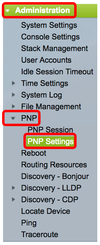
Step 2. Choose Administration > PNP > PNP Settings.

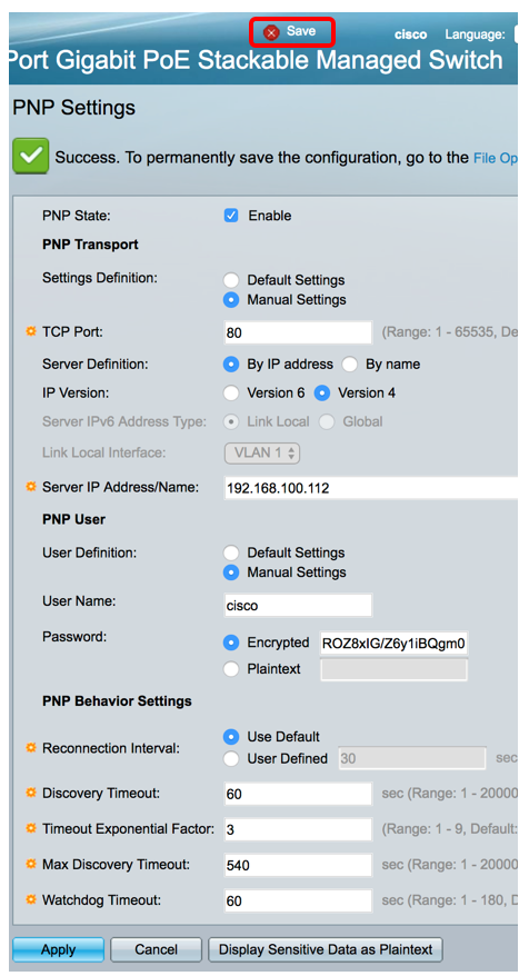
Step 3. (Optional) Check the Enable check box in the PNP State area to enable PNP.
Note: This feature is enabled by default.

Step 4. Choose one of the following options for locating configuration information regarding the transport protocol to use, the PNP server address, and the TCP port to use:
- Default Settings — If this option is chosen, the PNP settings are then taken from DHCP option 43. If some or all of the settings are not received from DHCP option 43, the following default values are used: default transport protocol HTTP, DNS name pnpserver for PNP server, and the port related to either HTTP or HTTPS.
Note: When selecting the Default Settings option, all fields in PNP Transport section are grayed out. If this option is chosen, skip to Step 11.
- Manual Settings — Manually set the protocol to use for PNP transport. The default is port 80 for HTTP. In this example, this option is chosen.

Step 5. (Optional) Enter the number of the TCP port in the TCP Port field. This is entered automatically by the system: 80 for HTTP and 443 for HTTPS. In this example, the default port of 80 is used.

Step 6. (Optional) Choose whether to specify the PNP server By IP address or By name.

Note: In this example, By IP address is chosen.
Step 7. (Optional) Click the desired IP Version radio button.
The options are:
- Version 6 — Denotes the IPv6 address type.
- Version 4 — Denotes the IPv4 address type. If this option is chosen, skip to Step 10.

Step 8. (Optional) If the Version 6 IP address type is chosen in Step 7, click the desired IPv6 address type.

The options are:
- Link Local — Denotes the IPv6 address uniquely identifies the host on a single network link.
- Global — Denotes the IPv6 address is a global unicast that is visible and reachable from other networks. If this option is chosen, skip to Step 10.
Note: In this example, Link Local is chosen.
Step 9. (Optional) If the Link Local IPv6 address type is chosen, choose a link local interface from the Link Local Interface drop-down list.

Note: In this example, VLAN 1 is chosen.
Step 10. Enter the SNTP server IP address or name. The format depends on which address type was selected.

Note: In this example, 192.168.100.112 is the IP address used.
Step 11. Configure the user information to be sent in PNP packets sent to the server. Select one of the following options:
- Default Settings — When selecting this option, the PNP username and password settings are taken from DHCP option 43. If this option is chosen, skip to Step 14.
- Manual Settings — Choose to manually configure PNP username and password. In this example, this option is chosen.

Step 12. In the User Name field, enter the username to be entered in the PNP packets. In this example, cisco is used.

Step 13. In the Password field, enter the password in either Encrypted or Plaintext form.

Note: In this example, Plaintext is chosen and Cisc01234$ password is entered.
Step 14. Configure the Reconnection Interval in seconds before attempting to reconnect the session after the connection is lost. In this example, Use Default is chosen which has the default value of 30 seconds.

Step 15. In the Discover Timeout field, enter the time to wait in seconds before attempting discovery again after a discovery of the PNP server failed. The default value is 60 seconds.

Step 16. In the Timeout Exponential Factor field, enter the value that triggers the discovery attempt exponentially by multiplying the previous timeout value by an exponential value and applying the result as timeout (if value is smaller than max timeout value). In this example, the default value of 3 is used.

Step 17. Enter the maximum value of timeout in the Max Discovery Timeout field. The value must be greater than the Discovery Timeout value.

Step 18. In the Watchdog Timeout field, enter the interval of time to wait for a reply from a PnP or file server during an active PNP session, such as during a file download process. In this example, 60 seconds is used.

Step 19. Click Apply to save the configured settings.
Step 20. (Optional) Click Save to save the configured settings to the startup configuration file.

You should now have successfully configured the PNP settings on your switch.
 Feedback