Configure the UDLD Settings on a Switch
Available Languages
Objective
Unidirectional Link Detection (UDLD) is a Layer 2 protocol that enables devices connected through fiber-optic or twisted-pair Ethernet cables to detect unidirectional links. A unidirectional link occurs whenever traffic from a neighboring device is received by the local device, but traffic from the local device is not received by the neighbor.
The purpose of UDLD is to detect ports on which the neighbor does not receive traffic from the local device (unidirectional link) and to shut down those ports. All connected devices must support UDLD for the protocol to successfully detect unidirectional links. If only the local device supports UDLD, it is not possible for the device to detect the status of the link. In this case, the status of the link is set to Undetermined. The user can configure whether ports in the Undetermined state are shut down or merely trigger notifications.
This article provides instructions on how to configure the UDLD settings on your switch.
Applicable Devices
- Sx250 Series
- Sx350 Series
- SG350X Series
- Sx550X Series
Software Version
- 2.3.5.63
Configure UDLD Settings
Configure UDLD Global Settings
Step 1. Log in to the web-based utility and choose Advanced from the Display Mode drop-down list.

Note: The available menu options may vary depending on the device model. In this example, SG550XG-8F8T is used.
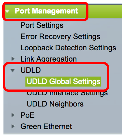
Step 2. Choose Port Management > UDLD > UDLD Global Settings.
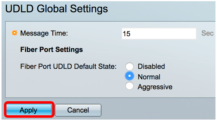
Step 3. In the Message Time field, enter the interval between sending UDLD messages. This field is relevant for both fiber and copper ports. The default value is 15 seconds.

Step 4. Choose one of the following options for the fiber port UDLD default state:
- Disabled — UDLD is disabled on all ports of the device. This option is chosen by default.
- Normal — The switch shuts down an interface if the link is unidirectional. If the link is undetermined, a notification is issued.
- Aggressive — The switch shuts down an interface if the link is unidirectional. If the link is bi-directional, the switch shuts down after the UDLD information times out. The port state is marked as undetermined.
Note: This area is only relevant for fiber ports. The UDLD state of copper ports must be configured individually in the UDLD Interface Settings page. For instructions, skip to the Configure UDLD Interface Settings section.

Note: In this example, Normal is chosen.
Step 5. Click Apply to save the configured settings.
You should now have successfully configured the UDLD global settings on your switch.
Configure UDLD Interface Settings
You can use the UDLD Interface Settings page of the web-based utility of the switch to change the UDLD state for a specific port. In this page, the state can be set for copper or fiber ports.
To configure UDLD for an interface, follow these steps:
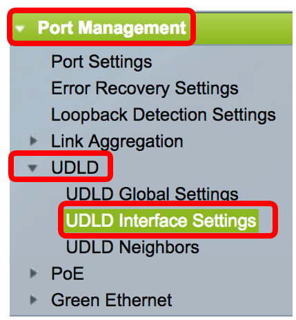
Step 1. Choose Port Management > UDLD > UDLD Interface Settings.
In the UDLD Port Setting Table, the information is displayed for all ports on which UDLD is enabled or if you have filtered only a certain group of ports, the information is displayed for that group of ports. The table displays the following information:
- Port — The port identifier.
- UDLD State — The possible states are:
- Bidirectional State — The possible states are:
- Number of Neighbors — The number of connected devices detected.
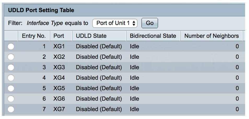
Step 2. (Optional) To choose a filter, choose a unit and click Go. In this example, Port of Unit 1 is chosen.

Note: If the switch is part of a stack, you can display the interfaces of other units in the stack by using this drop-down list.
Step 3. In the UDLD Port Setting Table, click the radio button of the interface you want to configure then click Edit.
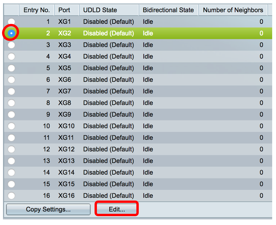
Note: In this example, port XG2 is chosen.
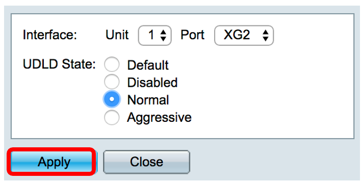
Step 4. The Interface area displays the chosen port in the UDLD Port Setting Table. You can use the Unit and Port drop-down lists to choose another unit and port to configure, respectively.

Note: In this example, port XG2 of Unit 1 is retained.
Step 5. Click the UDLD state of the chosen interface from the UDLD State area. If you choose Default, the port receives the value of the Fiber Port UDLD Default State in the UDLD Global Settings page.
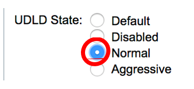
Note: In this example, Normal is chosen.
Step 6. Click Apply then click Close.
Step 7. (Optional) Click Save to save the configured settings to the startup configuration file.
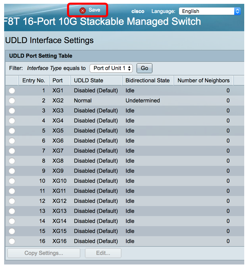
You should now have successfully configured the UDLD interface settings on your switch.
 Feedback