Configure Remote Log Server on a Switch
Available Languages
Objective
A System Log (Syslog) service simply accepts messages, and stores them in files or prints them according to a simple configuration file. This form of logging is the best available for Cisco devices because it can provide protected long-term storage for logs. This is useful both in routine troubleshooting and in incident handling.
The logs are saved on the local memory of the device and can also be forwarded over the network to a remote log server. Logs on the remote log server serve as a backup and are very useful for log merging and log analysis.
This article provides instructions on how you can configure remote log server on your switch.
Applicable Devices
- Sx250 Series
- Sx350 Series
- SG350X Series
- Sx500 Series
- Sx550X Series
Software Version
- 1.4.5.02 - Sx500 Series
- 2.2.0.66 - Sx250 Series, SG350 Series, Sx350X Series, Sx550X Series
Configure Remote Log Server
Configure Basic Remote Log Server
Step 1. Log in to the web-based utility and choose Administration > System Log > Remote Log Servers.
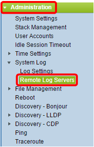
Step 2. Choose an option from the Server Definition radio buttons.
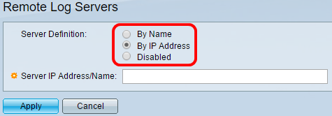
The options are:
- By Name - Indicates that the remote log server is identified by the name.
- By IP address - Indicates that the remote log server is identified by its IP address.
- Disabled - Disable Remote Log Server.
Note: In this example, By IP Address is chosen.
Step 3. Enter the server IP address or name in the Server IP Address/Name field.
Note: In this example, an IP address is entered.

Step 4. Click Apply.
You should now have configured the basic settings for the remote log server on your switch.
Configure Advanced Remote Log Server
Step 1. Log in to the web-based utility and choose Advanced in the Display Mode drop-down list.

Step 2. Choose Administration > System Log > Remote Log Servers.
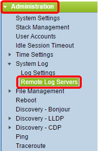
Step 3. (Optional) Choose the source interface whose IPv4 address will be used as the source IPv4 address of SYSLOG messages sent to SYSLOG servers.
Note: If the Auto option is chosen, the system takes the source IP address from the IP address defined on the outgoing interface. This is the default value.
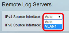
Note: In this example, VLAN1 is chosen.
Step 4. (Optional) Choose the source interface whose IPv6 address will be used as the source IPv6 address of SYSLOG messages sent to SYSLOG servers.
Note: If the Auto option is chosen, the system takes the source IP address from the IP address defined on the outgoing interface. This is the default value.
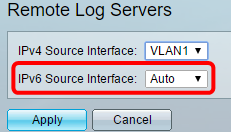
Note: In this example, Auto is chosen.
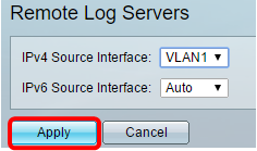
Step 5. Click Applyto save the configuration settings.
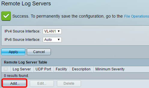
Step 6. In the Remote Log Server Table area, click Add.
Step 7. Choose a Receiver Definition radio button.
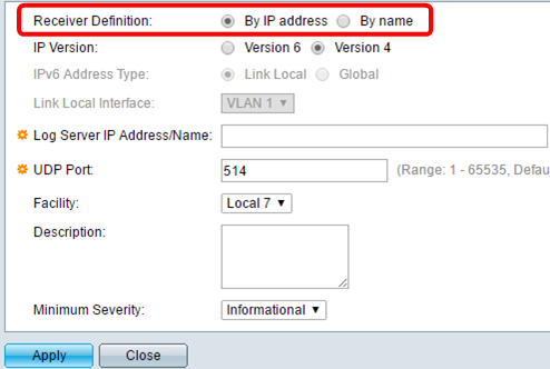
- By Name - Indicates that the remote log server is identified by the name.
- By IP address - Indicates that the remote log server is identified by its IP address.
Note: In this example, By IP address is chosen.
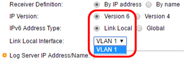
Step 8. Choose an IP version.
- Version 6 - Denotes the IPv6 address type.
- Version 4 - Denotes the IPv4 address type.
Step 9. (Optional) If the Version 6 IP address type is chosen in Step 8, click the desired IPv6 address Type.
- Link Local - Denotes the IPv6 address uniquely identifies hosts on a single network link.
- Global - Denotes the IPv6 address is a global unicast that is visible and reachable from other networks.
Step 10. (Optional) If the Link Local IPv6 Address Type is chosen in Step 9, choose the link local interface from the Link Local Interface drop-down list.
Step 11. Enter either the IP address or the name of the remote log server based upon your choice in the Server Definition field in the Log Server IP Address/Name field.
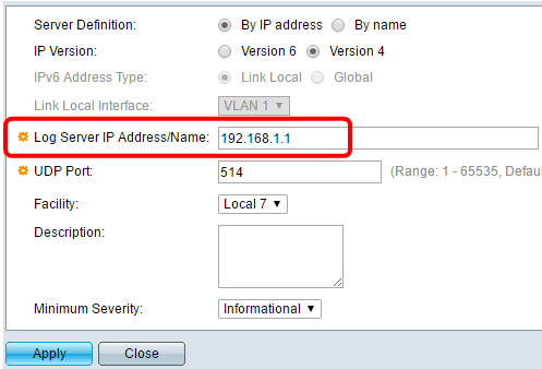
Step 12. Enter the UDP port number in the UDP Port field to which the log messages are sent. The default is 514.
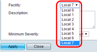
Step 13. Choose the desired facility value which describes the log messages that are sent to the server. Facility is a code name that is used to identify the remote syslog server targets. The Local 0 to Local 7 are available in the Facility drop-down list. Only one facility value can be assigned to a server. If a second facility code is assigned, the first facility value is overridden. The default is Local 7.
Step 14. Enter the user-defined description of the remote log server in the Description field.

Step 15. Choose the minimum severity level of the log messages that are to be sent to the remote server. The default value setting is Informational.
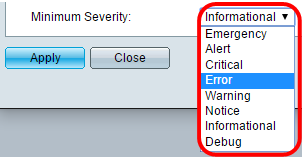
The Minimum Severity drop-down list has the following event severity levels which are listed from the highest severity to the lowest severity.
- Emergency - System is not usable.
- Alert - Action is needed.
- Critical - System is in a critical condition.
- Error - System is in error condition.
- Warning - System warning has occurred.
- Notice - System is functioning properly, but a system notice has occurred.
- Informational - Device Information.
Step 16. Click Apply to save the configuration settings.
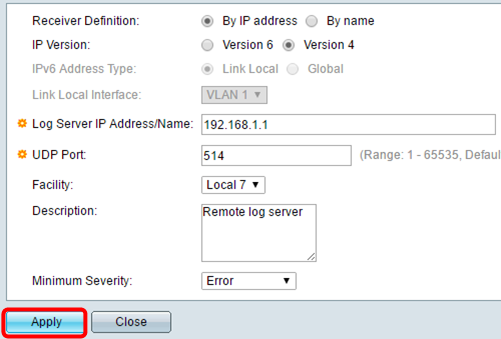
Step 17. Click Close. The Remote Log Server table area should display the new server.
Step 18. (Optional) Click Save to update the startup configuration file.
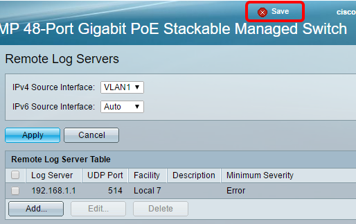
You should now have configured the advanced remote log server settings on your switch.
Revision History
| Revision | Publish Date | Comments |
|---|---|---|
1.0 |
13-Dec-2018 |
Initial Release |
 Feedback