Bandwidth Settings of Ingress and Egress Interfaces on SG/SF 250 Switches
Available Languages
Objective
Bandwidth refers to the amount of data that can be transferred through a network path. Bandwidth settings can be made different for incoming traffic and outgoing traffic. Ingress interfaces refer to interfaces with incoming traffic while egress interfaces refer to interfaces with outgoing traffic.
The objective of this document is to explain how to configure bandwidth settings on SG250 and SF250 switches.
Applicable Devices
- SF250
- SG250
- SG250X
Software Version
- 2.4.5.71
Configure Bandwidth Settings
Step 1. Log in to the web configuration utility of the switch.

Step 2. Choose Advanced from the drop-down menu of the Display Mode located at the top of the page.

Step 3. Click on Quality of Service > General > Bandwidth from the menu.
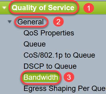
The Bandwidth page opens:
The Bandwidth Table contains the following fields for each interface:
• Ingress Rate Limit - Ingress traffic refers to the incoming traffic. When enabled, it shows the rate limit for Ingress (incoming) interfaces. For FE (Fast Ethernet) port the bandwidth assigned will be in the range 62 - 100,000 Kbps whereas for GE (Gigabit Ethernet) ports the bandwidth range will be in the range 62 - 1,000,000 Kbps.
- Status - Displays whether Ingress Rate Limit is enabled.
- Rate Limit (KBits/sec) - Displays the ingress rate limit for the port.
- % - Displays the ingress rate limit for the port divided by the total port bandwidth.
- CBS (Bytes) - Committed Burst Size (CBS) is the maximum burst size of data for the ingress interface in bytes of data that a network accepts. The CBS can be in the range of 3000 to 19,173,960 bytes.
• Egress Shaping Rate - Shows statistics of the Egress (outgoing) traffic.
- Status - Displays whether Egress Shaping Rates is enabled.
- CIR (KBits/sec) - Committed Information Rate (CIR) displays the maximum bandwidth for the egress interface. It specifies amount of guaranteed bandwidth on a frame relay service. This guarantees that frames which are within CIR level will be delivered but it is not guaranteed when frames exceed this limit. For FE ports the shaping rate is in the range 64 to 1,00,000 Kbps while for GE ports it is in the range 64 to 1,000,000 Kbps.
- CBS (Bytes) - Maximum burst size of data for the egress interface in bytes of data.

Step 4. Select an interface by clicking the appropriate
radio button of the interface for which you want to configure bandwidth
settings and click Edit.

A new window appears.
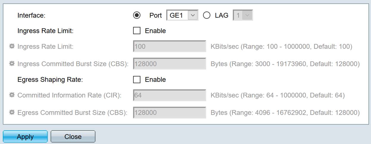
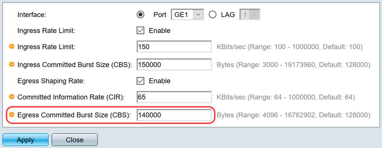
Step 5. Select Port interface if you want to apply bandwidth settings on a particular port or click LAG (Link Aggregation) if you want to apply bandwidth settings on a bundle of a few or all individual ports. Then choose a particular value from the drop-down list next to it.
Note: To configure LAG settings you can navigate to Port Management > Link Aggregation > LAG Management from the menu; select a LAG that you want to edit and add ports to that LAG.
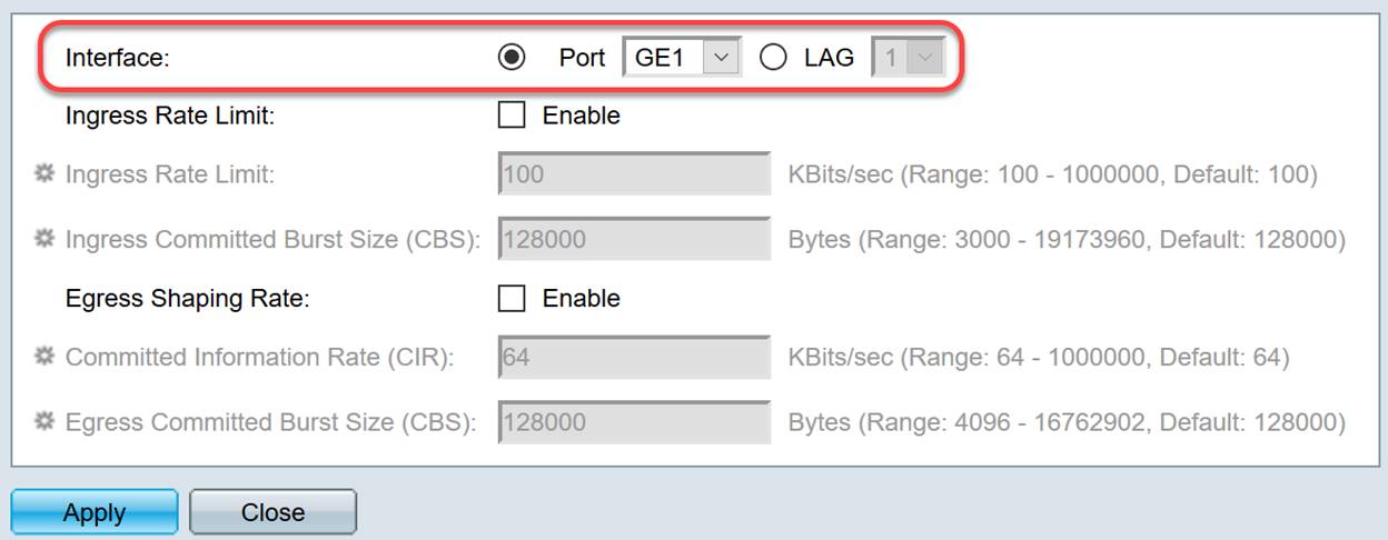
Step 6. (Optional) Check the Ingress Rate Limit check box if you want to define incoming traffic bandwidth.
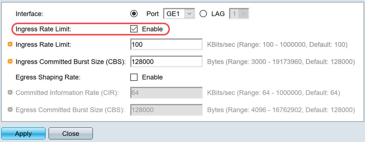
Note: If you did not check Ingress Rate Limit in Step 6 then skip to Step 9.
Step 7. Enter the value in the Ingress Rate Limit field.
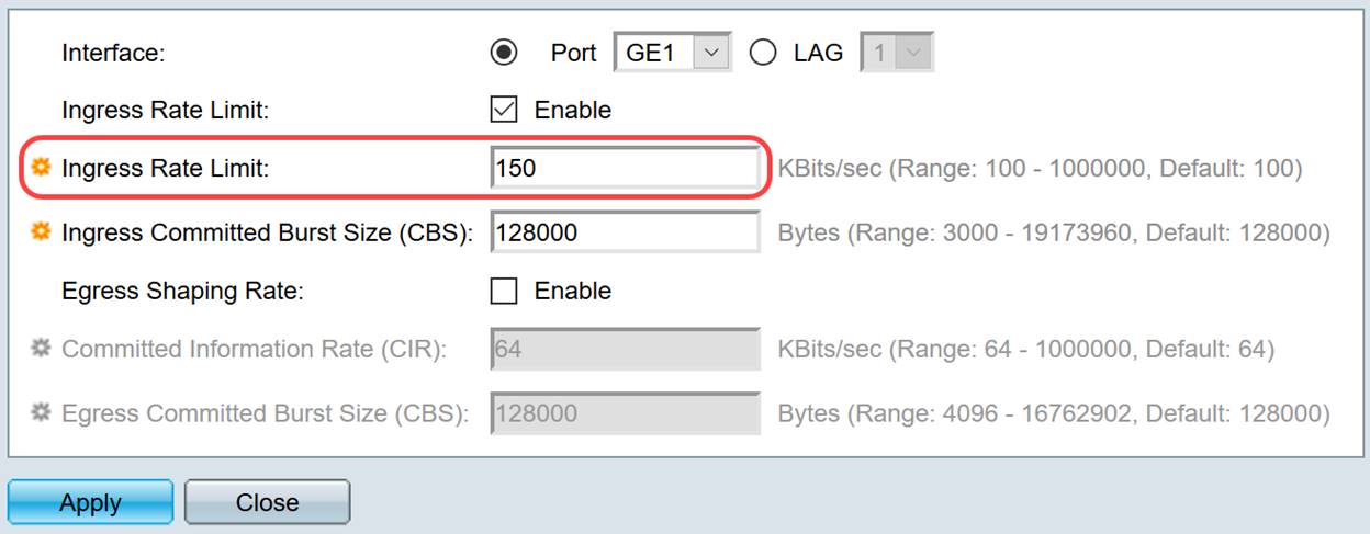
Note: The two Ingress Rate Limit fields do not appear when the interface type is LAG.
Step 8. Enter the value in the Ingress Committed Burst Size (CBS) field.
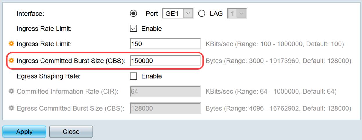
Note: Ingress Rate Limit and Ingress Committed Burst Size (CBS) fields get auto populated with the default values when the Ingress Rate Limit check box is enabled.
Step 9. (Optional) Check the Egress Shaping Rate check box if you want to define outgoing traffic bandwidth. Shaping Rate refers to the maximum bandwidth allowed on egress interfaces.
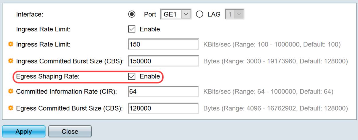
Note: If you did not check Egress Shaping Rate in Step 9 then skip to Step 12.
Step 10. Enter the value in the Committed Information Rate (CIR) field.
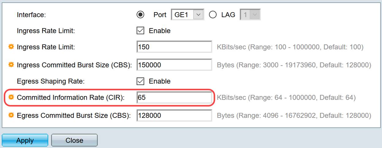
Step 11. Enter the required value in the Egress Committed Burst Size (CBS) field.
Note: This amount can be sent even if it temporarily increases the bandwidth beyond the allowed limit.
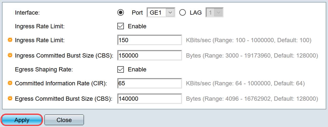
Step 12. Click Apply to save the settings.
Copy Settings
Step 1. To copy the settings of one interface to another or multiple interfaces, click the radio button of the source interface.

Step 2. Click Copy Settings.
A new window appears:

Step 3. In the provided field, enter the destination interface. To copy the same settings to multiple interfaces, separate the destination interfaces or ranges of interfaces with commas.

Step 4. Click Apply to copy the settings.

You should now have successfully configured bandwidth settings on the SG250 or SF250 switch.
Contact Cisco
- Open a Support Case

- (Requires a Cisco Service Contract)
 Feedback