Use TheGreenBow VPN Client to Connect with RV34x Series Router
Available Languages
Special Notice: Licensing Structure - Firmware versions 1.0.3.15 and later. Moving forward, AnyConnect will incur a charge for client licenses only.
For additional information on AnyConnect licensing on the RV340 series routers, check out the article AnyConnect Licensing for the RV340 Series Routers.
Introduction
A Virtual Private Network (VPN) connection allows users to access, send, and receive data to and from a private network by means of going through a public or shared network such as the Internet but still ensuring a secure connection to an underlying network infrastructure to protect the private network and its resources.
A VPN tunnel establishes a private network that can send data securely using encryption and authentication. Corporate offices mostly use VPN connection since it is both useful and necessary to allow their employees to have access to their private network even if they are outside the office.
The VPN allows a remote host to act as if they were located on the same local network. The router supports up to 50 tunnels. A VPN connection can be set up between the router and an endpoint after the router has been configured for Internet connection. The VPN client is entirely dependent on the settings of the VPN router to be able to establish a connection.
TheGreenBow VPN Client is a third-party VPN client application that makes it possible for a host device to configure a secure connection for site-to-site IPSec tunnel with the RV34x Series Router.
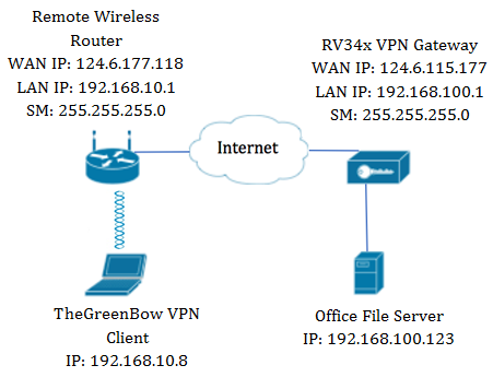
In the diagram, the computer will connect to the file server in the office outside its network to access its resources. To do this, TheGreenBow VPN Client in the computer will be configured in such a way that it would pull the settings from the RV34x VPN gateway.
Benefits of using a VPN connection
- Using a VPN connection helps protect confidential network data and resources.
- It provides convenience and accessibility for remote workers or corporate employees since they will be able to easily access the main office without having to be physically present and yet, still maintain the security of the private network and its resources.
- Communication using a VPN connection provides a higher level of security compared to other methods of remote communication. Advanced level of technology nowadays makes this possible, thus, protecting the private network from unauthorized access.
- Actual geographic location of the users are protected and not exposed to the public or shared networks like the Internet.
- Adding new users or group of users to the network is easy since VPNs are easily scalable. It is possible to make the network grow without the need for additional components or complicated configuration.
Risks of using a VPN connection
- Security risk due to misconfiguration. Since the design and implementation of a VPN can be complicated, it is necessary to entrust the task of configuring the connection to a highly knowledgeable and experienced professional in order to make sure that the security of the private network would not be compromised.
- Reliability. Since a VPN connection requires an Internet connection, it is important to have a provider with a proven and tested reputation to provide excellent Internet service and guarantee minimal to no downtime.
- Scalability. If it comes to a situation where there is a need to add new infrastructure or a new set of configurations, technical issues may arise due to incompatibility especially if involves different products or vendors other than the ones you are already using.
- Security issues for mobile devices. When initiating the VPN connection on a mobile device, security issues may arise especially when the mobile device is connected to the local network wirelessly.
- Slow connection speeds. If you are using a VPN client which provides free VPN service, it may be expected that your connection would also be slow since these providers do not prioritize connection speeds.
Prerequisites for Using TheGreenBow VPN Client
The following items must be configured on the VPN router first and will be applied to TheGreenBow VPN Client by clicking here to establish a connection.
- Create a Client-to-Site Profile on the VPN Gateway
- Create a User Group on the VPN Gateway
- Create User Account on the VPN Gateway
- Create an IPSec Profile on the VPN Gateway
- Configure the Phase I and Phase II Settings on the VPN Gateway
Applicable Devices
- RV34x Series
Software Version
- 1.0.01.17
Use TheGreenBow VPN Client
Create a Client-to-Site Profile on the Router
Step 1. Log in to the web-based utility of the RV34x Router and choose VPN > Client-to-Site.
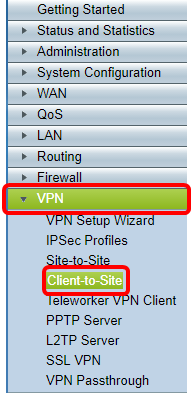
Note: The images in this article are taken from the RV340 Router. Options may vary, depending on the model of your device.
Step 2. Click Add.

Step 3. Click 3rd Party Client.
Note: AnyConnect is an example of a Cisco VPN Client, while TheGreenBow VPN Client is an example of a third-party VPN Client.

Note: In this example, 3rd Party Client is chosen.
Step 4. Under the Basic Settings tab, check the Enable check box to ensure that the VPN profile is active.

Step 5. Enter a name for the VPN connection in the Tunnel Name field.

Note: In this example, Client is entered.
Step 6. Choose the Interface to be used from the Interface drop-down list. The options are WAN1, WAN2, USB1, and USB2 which will use the corresponding interface on the router for the VPN connection.

Note: The options depend on the model of router you are using. In this example, WAN1 is chosen.
Step 7. Choose an IKE authentication method. The options are:
- Preshared Key — This option will let us use a shared password for the VPN connection.
- Certificate — This option uses a digital certificate that contains information such as the name, or IP address, serial number, expiration date of the certificate, and a copy of the public key of the bearer of the certificate.
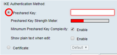
Note: In this example, Preshared Key is chosen.
Step 8. Enter the connection password in the Preshared Key field.
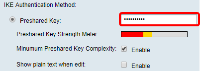
Step 9. (Optional) Uncheck the Minimum Preshared Key Complexity Enable check box to be able to use a simple password.
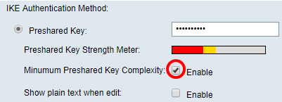
Note: In this example, Minimum Preshared Key Complexity is left enabled.
Step 10. (Optional) Check the Show plain text when edit Enable check box to show the password in plain text.
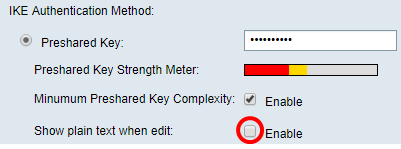
Note: In this example, Show plain text when the edit is left disabled.
Step 11. Choose a local identifier from the Local Identifier drop-down list. The options are:
- Local WAN IP — This option uses the IP address of the Wide Area Network (WAN) Interface of the VPN gateway.
- IP Address — This option allows you to manually enter an IP address for the VPN connection.
- FQDN — This option is also known as Fully Qualified Domain Name (FQDN). It lets you use a complete domain name for a specific computer on the Internet.
- User FQDN — This option lets you use a complete domain name for a specific user on the Internet.

Note: In this example, Local WAN IP is chosen. With this option, the Local WAN IP is automatically detected.
Step 12. (Optional) Choose an identifier for the remote host. The options are:
- IP Address — This option uses the WAN IP address of the VPN client.
- FQDN — This option lets you use a complete domain name for a specific computer on the Internet.
- User FQDN — This option lets you use a complete domain name for a specific user on the Internet.

Note: In this example, IP Address is chosen.
Step 13. Enter the remote identifier in the Remote Identifier field.

Note: In this example, 124.6.115.177 is entered.
Step 14. (Optional) Check the Extended Authentication check box to activate the feature. When activated, this will provide an additional level of authentication that will require remote users to key in their credentials before being granted access to the VPN.

Note: In this example, Extended Authentication is left unchecked.
Step 15. Under Group Name, click Add.

Step 16. Choose the group that will be using extended authentication from the Group Name drop-down list.

Note: In this example, VPN is chosen.
Step 17. Under Pool Range for Client LAN, enter the first IP address that can be assigned to a VPN client in the Start IP field.

Note: In this example, 10.10.100.100 is entered.
Step 18. Enter the last IP address that can be assigned to a VPN client in the End IP field.

Note: In this example, 10.10.100.245 is entered.
Step 19. Click Apply.

Step 20. Click Save.

You should now have configured the Client-to-Site Profile on the router for TheGreenBow VPN Client.
Step 1. Log in to the web-based utility of the router and choose System Configuration > User Groups.
Note: The images in this article are from an RV340 Router. Options may vary depending on the model of your device.
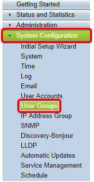
Step 2. Click Add to add a User Group.
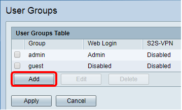
Step 3. In the Overview area, enter the name of the group in the Group Name field.
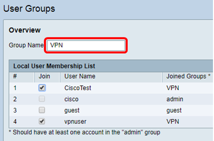
Note: In this example, VPN is used.
Step 4. Under Local Membership List, check the check boxes of the user names that need to be in the same group.

Note: In this example, CiscoTest and vpnuser are chosen.
Step 5. Under Services, choose a permission to be granted to the users in the group. The options are:
- Disabled — This option means that members of the group are not permitted to access the web-based utility through a browser.
- Read Only — This option means that the members of the group can only read the status of the system after they log in. They cannot edit any of the settings.
- Administrator — This option gives the members of the group read and write privileges, and be able to configure the system status.

Note: In this example, Read Only is chosen.
Step 6. In the EzVPN/3rd Party Profile Member In-use Table, click Add.

Step 7. Choose a profile from the Select a Profile drop-down list. The options may vary, depending on the profiles that have been configured on the VPN gateway.
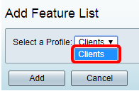
Note: In this example, Clients is chosen.
Step 8. Click Add.

Step 9. Click Apply.
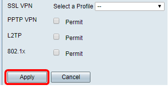
Step 10. Click Save.

You should now have successfully created a user group on the RV34x Series Router.
Step 1. Log in to the web-based utility of the router and choose System Configuration > User Accounts.
Note: The images in this article are taken from an RV340 Router. Options may vary depending on the model of your device.
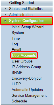
Step 2. In the Local User Membership List area, click Add.
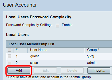
Step 3. Enter a name for the user in the User Name field.
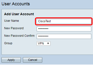
Note: In this example, CiscoTest is entered.
Step 4. Enter the user password in the New Password field.

Step 5. Confirm the password in the New Password Confirm box.

Step 6. Choose a group from the Group drop-down list. This is the group that the user will be associated to.
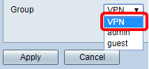
Note: In this example, VPN is chosen.
Step 7. Click Apply.
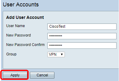
Step 8. Click Save.

You should now have created a User Account on your RV34x Series Router.
Step 1. Log in to the web-based utility of the RV34x Router and choose VPN > IPSec Profiles.
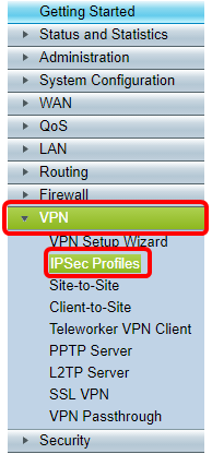
Note: The images in this article are taken from the RV340 Router. Options may vary depending on the model of your device.
Step 2. The IPSec Profiles Table shows the existing profiles. Click Add to create a new profile.
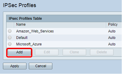
Note: Amazon_Web_Services, Default, and Microsoft_Azure are default profiles.
Step 3. Create a name for the profile in the Profile Name field. The profile name must contain only alphanumeric characters and an underscore (_) for special characters.

Note: In this example, Client is entered.
Step 4. Click a radio button to determine the key exchange method the profile will use to authenticate. The options are:
- Auto — Policy parameters are set automatically. This option uses an Internet Key Exchange (IKE) policy for data integrity and encryption key exchanges. If this is chosen, the configuration settings under the Auto Policy Parameters area are enabled. If this option is chosen, skip to Configure Auto Settings.
- Manual — This option allows you to manually configure the keys for data encryption and integrity for the VPN tunnel. If this is chosen, the configuration settings under the Manual Policy Parameters area are enabled. If this option is chosen, skip to Configure Manual Settings.

Note: For this example, Auto was chosen.
Configure the Phase I and Phase II Settings
Step 1. In the Phase 1 Options area, choose the appropriate Diffie-Hellman (DH) group to be used with the key in Phase 1 from the DH Group drop-down list. Diffie-Hellman is a cryptographic key exchange protocol which is used in the connection to exchange pre-shared key sets. The strength of the algorithm is determined by bits. The options are:
- Group2-1024 bit — This option computes the key slower, but is more secure than Group 1.
- Group5-1536 bit — This option computes the key the slowest, but is the most secure.

Note: In this example, Group5-1536 bit is chosen.
Step 2. From the Encryption drop-down list, choose an encryption method to encrypt and decrypt Encapsulating Security Payload (ESP) and Internet Security Association and Key Management Protocol (ISAKMP). The options are:
- 3DES — Triple Data Encryption Standard.
- AES-128 — Advanced Encryption Standard uses a 128-bit key.
- AES-192 — Advanced Encryption Standard uses a 192-bit key.
- AES-256 — Advanced Encryption Standard uses a 256-bit key.

Note: AES is the standard method of encryption over DES and 3DES for its greater performance and security. Lengthening the AES key will increase security with a drop in performance. In this example, AES-128 is chosen.
Step 3. From the Authentication drop-down list, choose an authentication method that will determine how ESP and ISAKMP are authenticated. The options are:
- MD5 — Message-Digest Algorithm has a 128-bit hash value.
- SHA-1 — Secure Hash Algorithm has a 160-bit hash value.
- SHA2-256 — Secure Hash Algorithm with a 256-bit hash value.
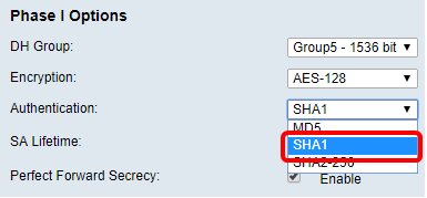
Note: MD5 and SHA are both cryptographic hash functions. They take a piece of data, compact it, and create a unique hexadecimal output that typically cannot be reproduced. In this example, SHA1 is chosen.
Step 4. In the SA Lifetime field, enter a value between 120 and 86400. This is the length of time the Internet Key Exchange (IKE) Security Association (SA) will remain active in the phase. The default value is 28800.
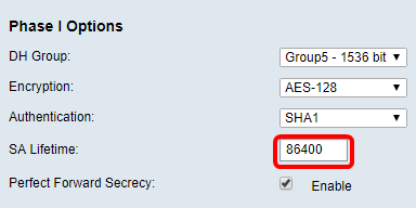
Note: In this example, 86400 is entered.
Step 5. (Optional) Check the Enable Perfect Forward Secrecy check box to generate a new key for IPSec traffic encryption and authentication.
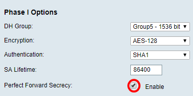
Note: In this example, Perfect Forward Secrecy is enabled.
Step 6. From the Protocol Selection drop-down list in the Phase II Options area, choose a protocol type to apply to the second phase of the negotiation. The options are:
- ESP — This option encapsulates the data to be protected. If this option is chosen, proceed to Step 7 to choose an encryption method.
- AH — This option is also known as Authentication Header (AH). It is a security protocol which provides data authentication and optional anti-replay service. AH is embedded in the IP datagram to be protected. If this option is chosen, skip to Step 8.
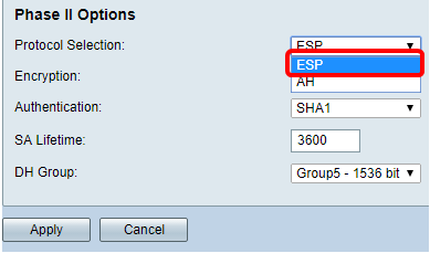
Note: In this example, ESP is chosen.
Step 7. If ESP was chosen in Step 6, choose an authentication method that will determine how ESP and ISAKMP are authenticated. The options are:
- 3DES — Triple Data Encryption Standard
- AES-128 — Advanced Encryption Standard uses a 128-bit key.
- AES-192 — Advanced Encryption Standard uses a 192-bit key.
- AES-256 — Advanced Encryption Standard uses a 256-bit key.

Note: In this example, AES-128 is chosen.
Step 8. From the Authentication drop-down list, choose an authentication method that will determine how ESP and ISAKMP are authenticated. The options are:
- MD5 — Message-Digest Algorithm has a 128-bit hash value.
- SHA-1 — Secure Hash Algorithm has a 160-bit hash value.
- SHA2-256 — Secure Hash Algorithm with a 256-bit hash value.
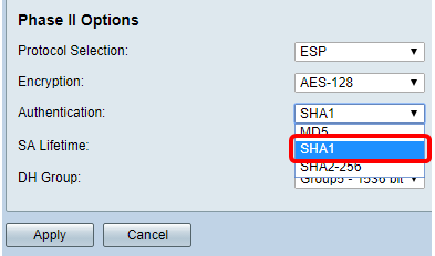
Note: In this example, SHA1 is chosen.
Step 9. In the SA Lifetime field, enter a value between 120 and 28800. This is the length of time the IKE SA will remain active in this phase. The default value is 3600.
Step 10. From the DH Group drop-down list, choose a DH group to be used with the key in Phase 2. The options are:
- Group2-1024 bit — This option computes the key slower, but is more secure than Group1.
- Group5-1536 bit — This option computes the key the slowest, but is the most secure.
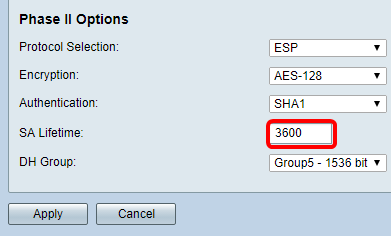
Note: In this example, 3600 is entered.
Step 11. Click Apply.
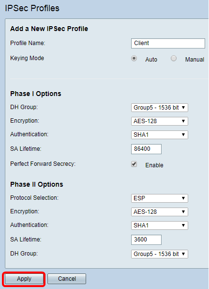
Step 12. Click Save to save the configuration permanently.

You should now have successfully configured an Automatic IPSec Profile on your RV34x Series Router.
Step 1. In the SPI-Incoming field, enter a hexadecimal value from 100 to FFFFFFF for the Security Parameter Index (SPI) tag for incoming traffic on the VPN connection. The SPI tag is used to distinguish the traffic of one session from the traffic of other sessions.

Note: In this example, 0xABCD is entered.
Step 2. In the SPI-Outgoing field, enter a hexadecimal value from 100 to FFFFFFF for the SPI tag for outgoing traffic on the VPN connection.

Note: In this example, 0x1234 is entered.
Step 3. Choose an encryption value from the drop-down list. The options are:
- 3DES — Triple Data Encryption Standard
- AES-128 — Advanced Encryption Standard uses a 128-bit key.
- AES-192 — Advanced Encryption Standard uses a 192-bit key.

Note: In this example, AES-256 is chosen.
Step 4. In the Key-In field, enter a key for the inbound policy. The length of the key will depend on the algorithm chosen in Step 3.

Note: In this example, 123456789123456789123… is entered.
Step 5. In the Key-Out field, enter a key for the outgoing policy. The length of the key will depend on the algorithm chosen in Step 3.

Note: In this example, 1a1a1a1a1a1a1a12121212… is entered.
Step 6. Choose an authentication method from the Authentication drop-down list. The options are:
- MD5 — Message-Digest Algorithm has a 128-bit hash value.
- SHA-1 — Secure Hash Algorithm has a 160-bit hash value.
- SHA2-256 — Secure Hash Algorithm with a 256-bit hash value.

Note: In this example, MD5 is chosen.
Step 7. In the Key-In field, enter a key for the inbound policy. The length of the key will depend on the algorithm chosen in Step 6.

Note: In this example, 123456789123456789123… is entered.
Step 8. In the Key-Out field, enter a key for the outgoing policy. The length of the key will depend on the algorithm chosen in Step 6.

Note: In this example, 1a1a1a1a1a1a1a12121212… is entered.
Step 9. Click  .
.
Step 10. Click Save to save the configuration permanently.

You should now have successfully configured a Manual IPSec Profile on an RV34x Series Router.
Configure TheGreenBow VPN Client Software
Configure Phase 1 Settings
Step 1. Right-click TheGreenBow VPN Client icon and choose Run as administrator.

Step 2. On the left pane under VPN configuration, right-click IKE V1 and choose New Phase 1.
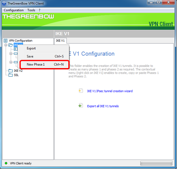
Step 3. In the Authentication tab under Addresses, verify that the IP address in the Interface area is the same as the WAN IP address of the computer where TheGreenBow VPN Client is installed.
Note: In this example, the IP address is 124.6.177.118.

Step 4. Enter the address of the remote gateway in the Remote Gateway field.
Note: In this example, the IP address of the remote RV34x Router is 124.6.115.177.

Step 5. Under Authentication, choose the authentication type. The options are:
- Preshared Key — This option will let the user use a password that has been configured on the VPN gateway. The password has to be matched by the user to be able to establish a VPN tunnel.
- Certificate — This option will utilize a certificate to complete the handshake between the VPN Client and the VPN Gateway.
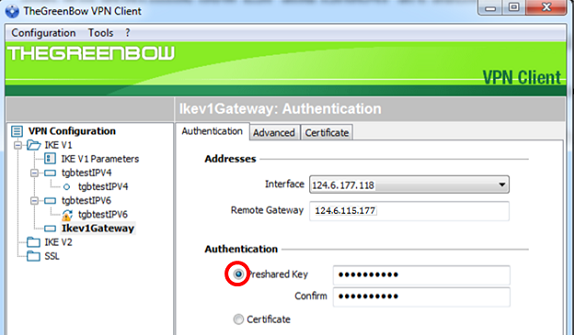
Note: In this example, Preshared Key is chosen to match the configuration of the RV34x VPN Gateway.
Step 6. Enter the Preshared Key configured in the router.
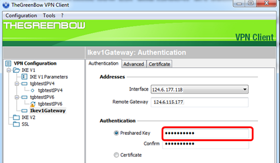
Step 7. Enter the same Preshared Key in the Confirm field.

Step 8. Under IKE, set the Encryption, Authentication, and Key Group settings to match the configuration of the router.
Step 9. Click the Advanced tab.

Step 10. (Optional) Under Advanced features, check the Mode Config and Aggressive Mode check boxes and set the NAT-T setting to Automatic.
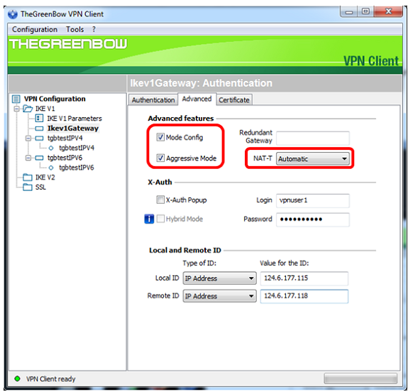
Note: With Mode Config enabled, TheGreenBow VPN Client will pull settings from the VPN gateway to attempt to establish a tunnel while enabling Aggressive Mode and NAT-T make establishing a connection faster.
Step 11. (Optional) Under X-Auth, check the X-Auth Popup check box to automatically pull up the login window when starting a connection. The login window is where the user enters his credentials to be able to complete the tunnel.
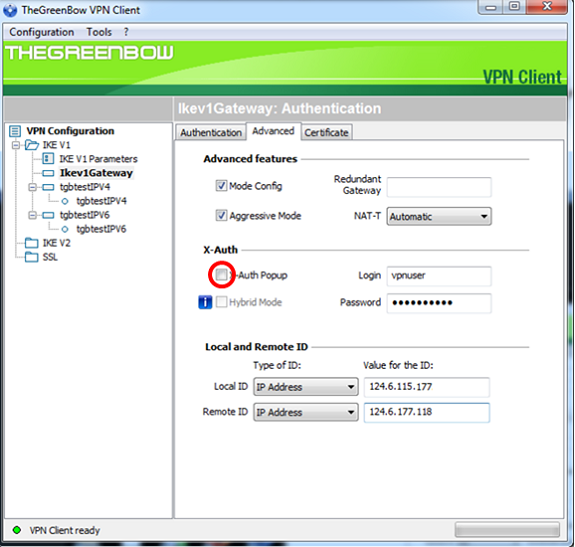
Note: In this example, X-Auth Popup is not checked.
Step 12. Enter your username in the Login field. This is the user name configured for creating a user group in the VPN gateway.

Step 13. Enter your password in the Password field.

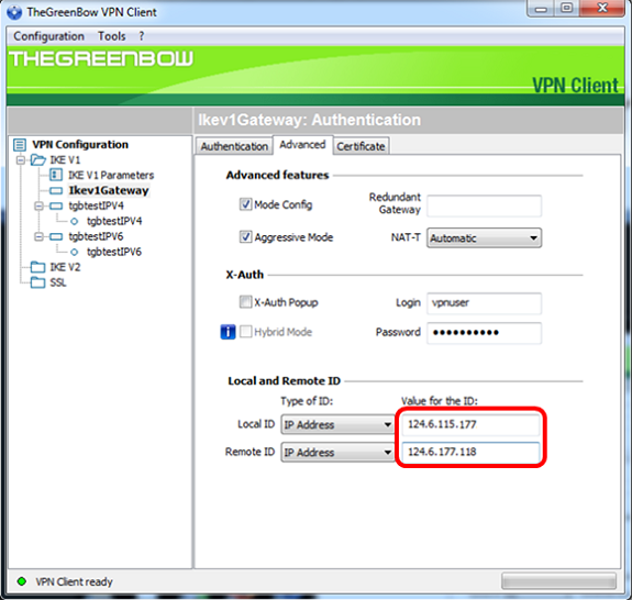
Step 14. Under Local and Remote ID, set the Local ID and the Remote ID to match the settings of the VPN gateway.

Note: In this example, both Local ID and Remote ID are set to IP Address to match the settings of the RV34x VPN gateway.
Step 15. Under Value for the ID, enter the local ID and remote ID in their respective fields.
Step 16. Click Configuration > Save to save the settings.

Configure Phase 2 Settings
Step 1. Right-click Ikev1Gateway.
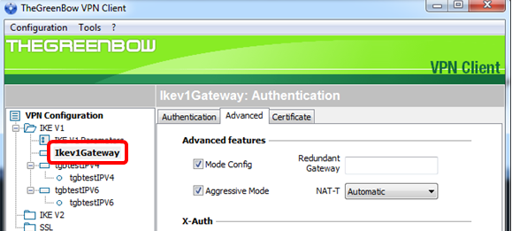
Step 2. Choose New Phase 2.

Step 3. Click the IPsec tab.
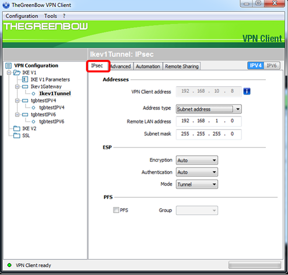
Step 4. Choose the address type that the VPN client can access from the Address type drop-down list.
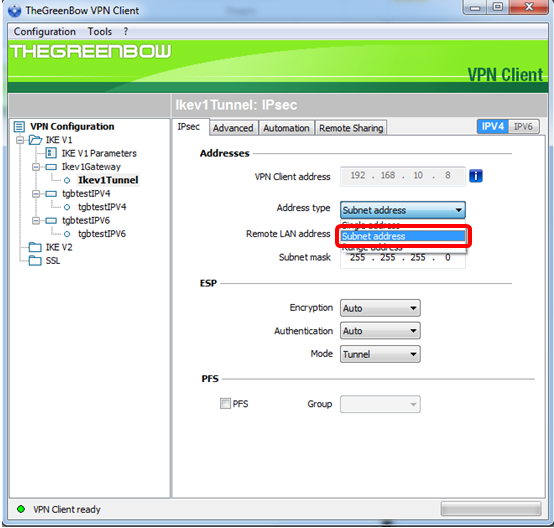
Note: In this example, Subnet address is chosen.
Step 5. Enter the network address that should be accessed by the VPN tunnel in the Remote LAN address field.
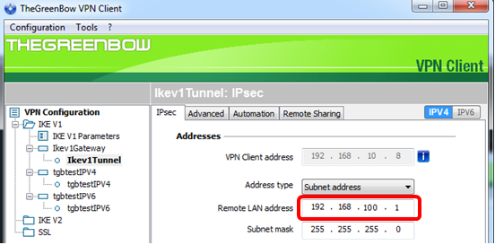
Note: In this example, 192.168.100.1 is entered.
Step 6. Enter the subnet mask of the remote network in the Subnet mask field.
Note: In this example, 255.255.255.0 is entered.
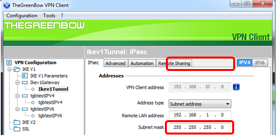
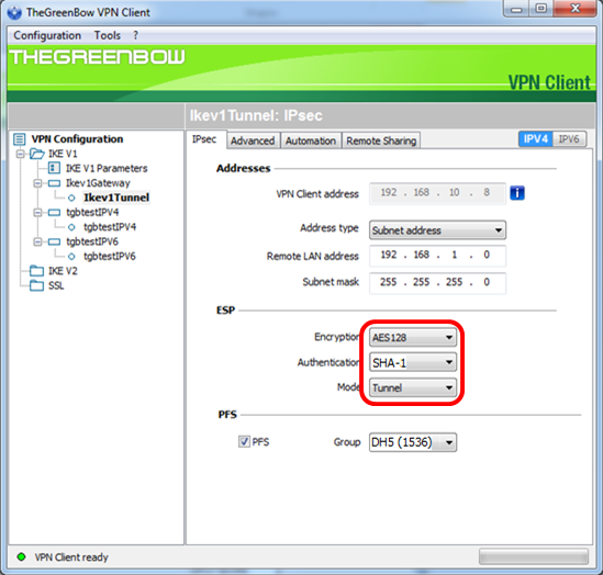
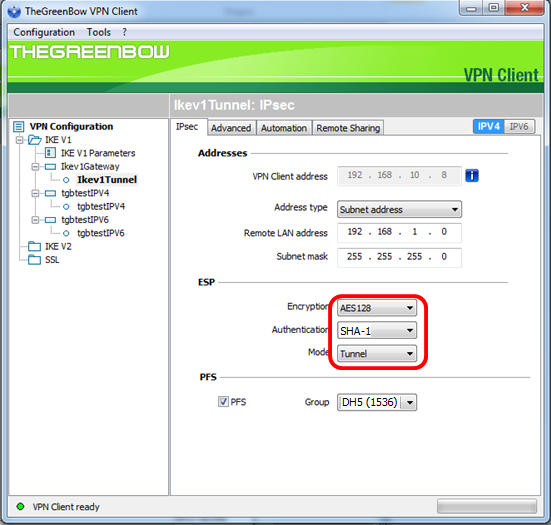
Step 7. Under ESP, set the Encryption, Authentication, and Mode to match the settings of the VPN gateway.
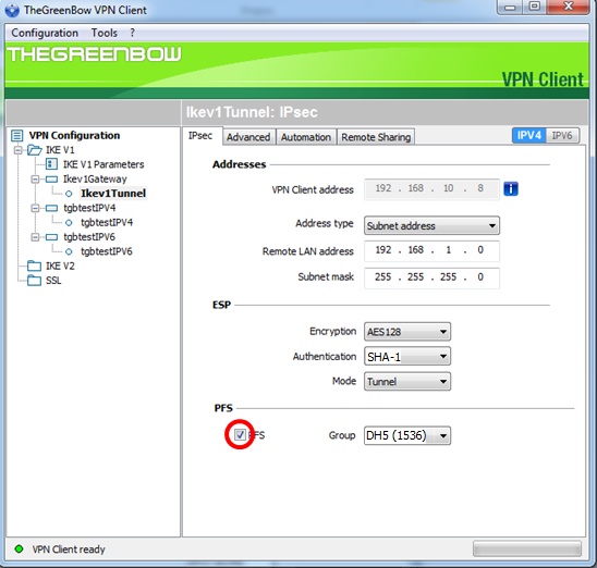
Step 8. (Optional) Under PFS, check the PFS check box to enable Perfect Forward Secrecy (PFS). PFS generates random keys for encrypting the session.
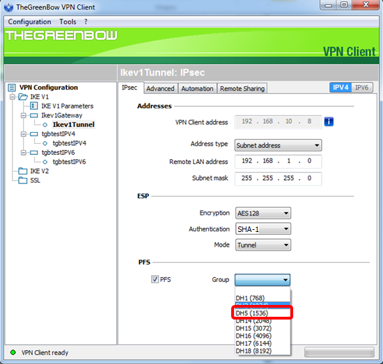
Step 9. Choose a PFS group setting from the Group drop-down list.
Note: In this example, DH5 (1536) is chosen to match the DH Group setting of the router.
Step 10. Right-click Configuration and choose Save.
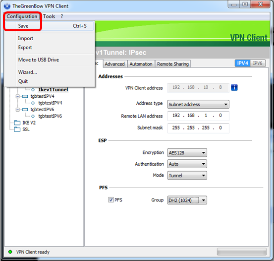
You should now have successfully configured TheGreenBow VPN Client to connect to the RV34x Series Router through VPN.
Start a VPN Connection
Step 1. Right-click TheGreenBow VPN Client and choose Run as administrator.
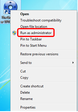
Step 2. Choose the VPN connection that you need to use and then click OPEN. The VPN connection should start automatically.

Note: In this example, the configured Ikev1Gateway was chosen.
Verify the VPN Status
Step 1. Login to the web-based utility of the VPN gateway.
Step 2. Choose Status and Statistics > VPN Status.
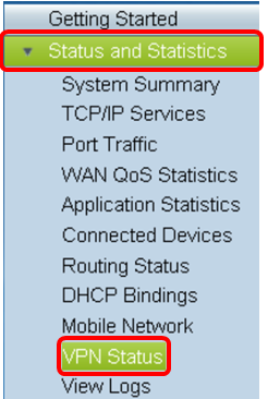
Step 3. Under Client-to-Site Tunnel Status, check the Connections column of the Connection Table.
Note: In this example, one VPN connection has been established.

You should now have successfully verified the VPN connection status on the RV34x Series Router. TheGreenBow VPN Client is now configured to connect to the router through VPN.
 Feedback