Introduction
This document describes the step-by-step configuration of a Site-to-Site Secure Internet Gateway (SIG) VPN tunnel on Secure Firewall Threat Defense.
Prerequisites
Requirements
Cisco recommends that you have knowledge of these topics:
- Umbrella Admin Portal
- Secure Firewall Management Center (FMC)
Components Used
The information in this document is based on these software and hardware versions.
- Umbrella Admin Portal
- Secure Firewall Version 7.2
The information in this document was created from the devices in a specific lab environment. All of the devices used in this document started with a cleared (default) configuration. If your network is live, ensure that you understand the potential impact of any command.
Network Diagram
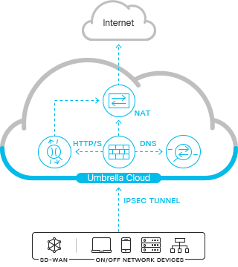
Umbrella Network Tunnel Configuration
Network Tunnel
Login to Umbrella Dashboard:

Navigate to Deployments > Network Tunnels > Add.
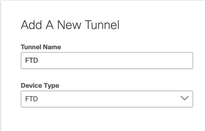
Add a New Tunnel, choose the device type as FTD, and name it appropriately.
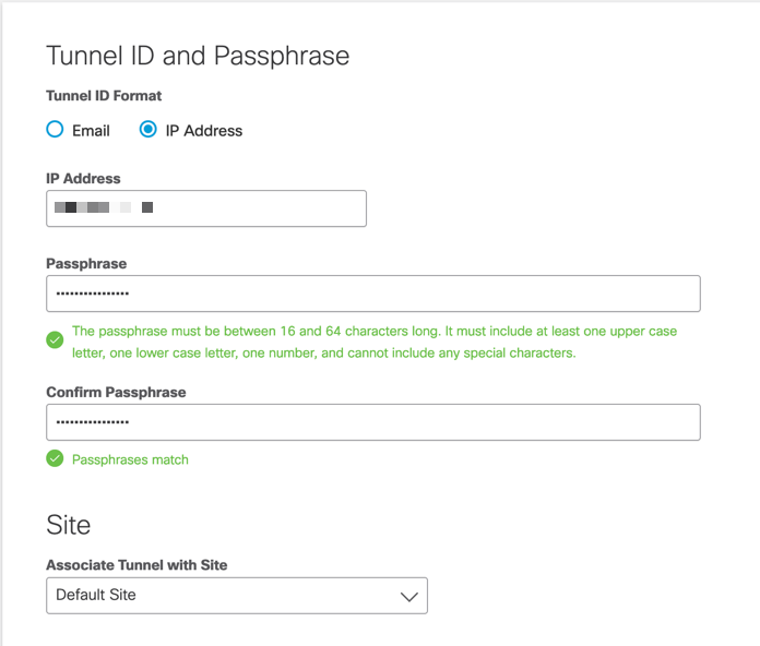
Enter the Public IP address of the FTD along with a secure pre-shared key.
Attach the tunnel to the appropriate site for firewalling and traffic inspection policies.
Configuration from Umbrella Portal is now complete.
Navigate to Umbrella Portal when the tunnel is connected in order to confirm the VPN status.
Secure Firewall Management Center Configuration
Configure Site-to-Site
Navigate to Devices > Site-to-Site :
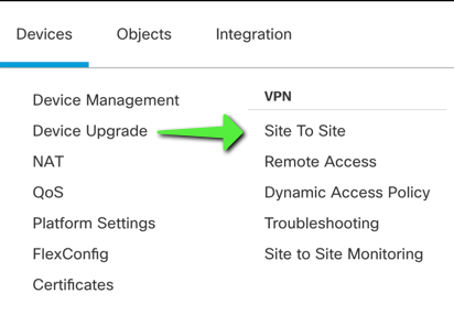
Add New Site-to-Site Tunnel
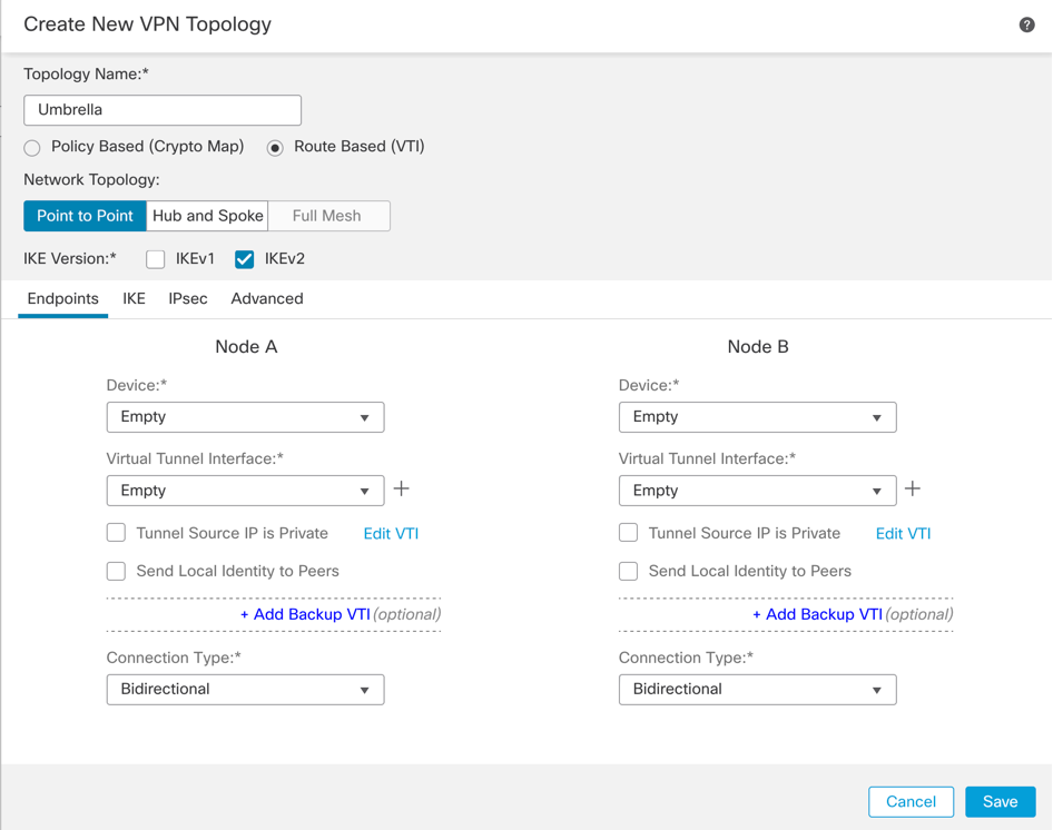
Name the Topology and choose Route-based VTI:
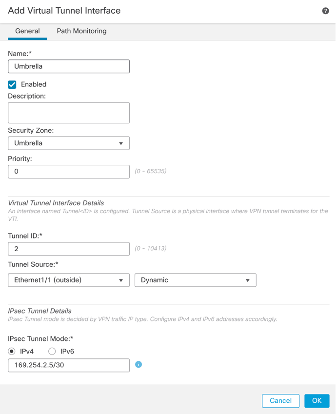
Add a New Virtual Tunnel Interface
- Name the Tunnel Interface
- Apply a New Security Zone to the Interface
- Assign a Tunnel ID number between 0-10413
- Choose Tunnel source (Interface with Public IP defined in Umbrella Portal)
- Create a non-routable/30 subnet for use with the VPN. For example, 169.254.72.0/30
Configure Topology Nodes
Assign FTD to Node A and Umbrella to Extranet Node B:
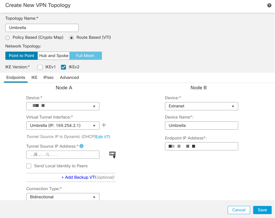
Endpoint IP addresses for use with Umbrella Data Centers can be found here.
Choose the Data Center that is closest to the physical location of the device.
Define IKEv2 Phase 1 Parameters:
Acceptable parameters for tunnel negotiation can be found here.
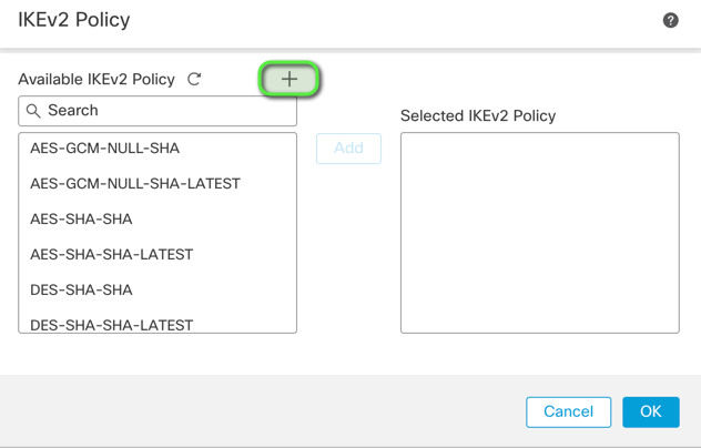
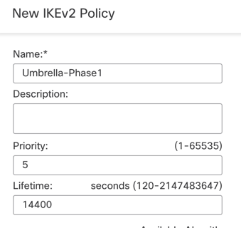
Navigate to the IKE tab and create a new IKEv2 Policy:
- Assign appropriate priority to avoid it from conflicting with the existing policies.
- Phase 1 lifetime is 14400 seconds.
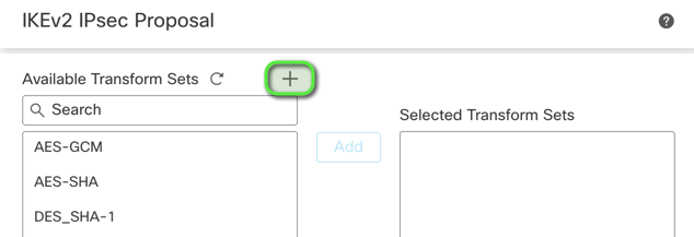
Define IPsec Phase 2 Parameters:
- Acceptable parameters for tunnel negotiation can be found here.
- Navigate to the
IPsec tab and create a new IPsec Proposal.
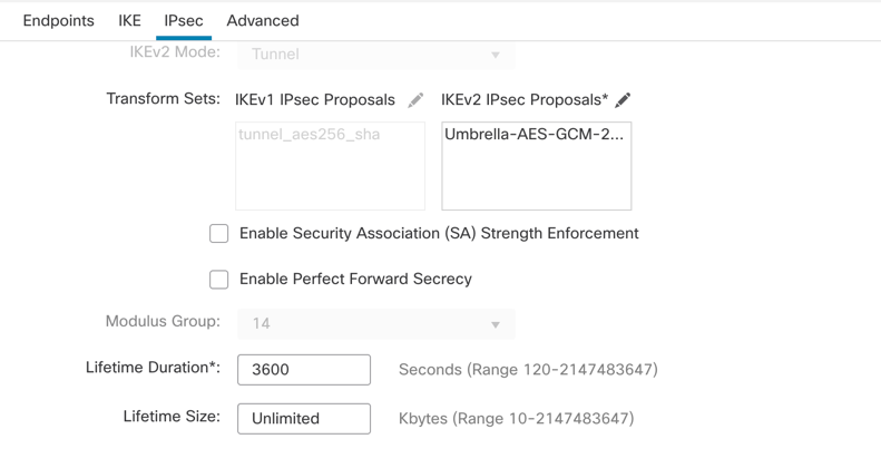
Ensure that Phase 2 parameters match this:
Save Topology and Deploy to the Firewall.
Configure Policy Based Routing (PBR)
Navigate to Devices > Device Management > Select the FTD/HA Pair > Routing > Policy Based Routing.
Add New Policy.

Configure the Forwarding Actions:
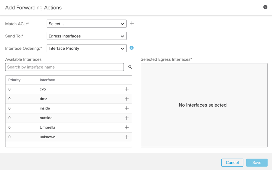
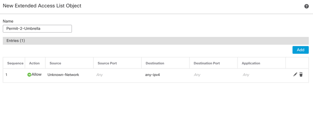
Create the Match ACL for the traffic that must navigate through the SIG tunnel:

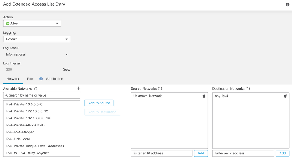
Add Access Control Entries defining the Umbrella SIG traffic:
-
- Source Networks define internal traffic.
- Destination Networks are the remote networks that must be inspected by Umbrella.
Completed Extended ACL:
Configure Send To:
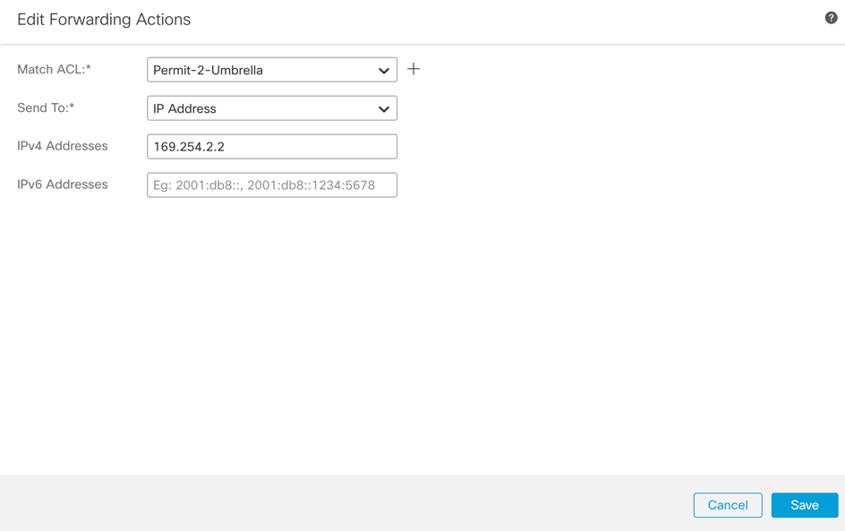
Define the Send To IPv4 address as the second available IP in the /30 subnet.

Note: This IP address is not defined in Umbrella. It is only needed for traffic forwarding.
Completed PBR:

Make note of the ingress interface, this is needed later for Access Control Policy (ACP) and Network Address Translation (NAT) configuration.
Save Configuration and Deploy to the Firewall.
Configure NAT and ACP
Navigate to Devices > NAT.
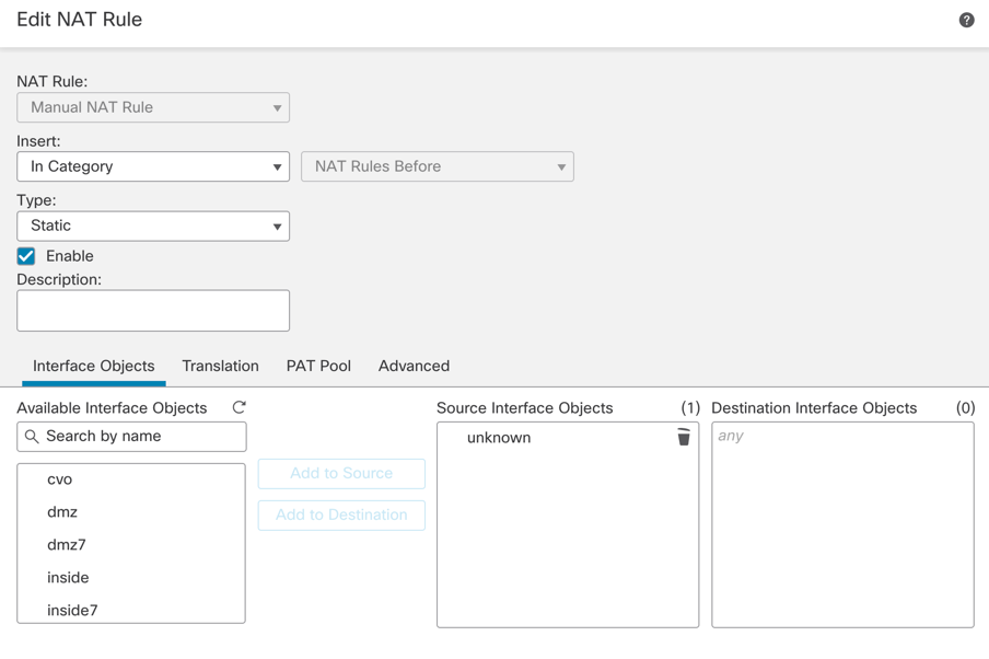
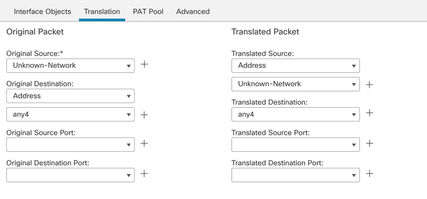
Create a new manual NAT rule like this:
-
- Source Interface – Internal protected source.
- Destination Interface – Any – This allows the traffic to be diverted to the VTI.
Translation:
-
- Original and Translated Source - Internal protected network object
- Original and Translated Destination – any4 – 0.0.0.0/0
Navigate to Policy > Access Control.
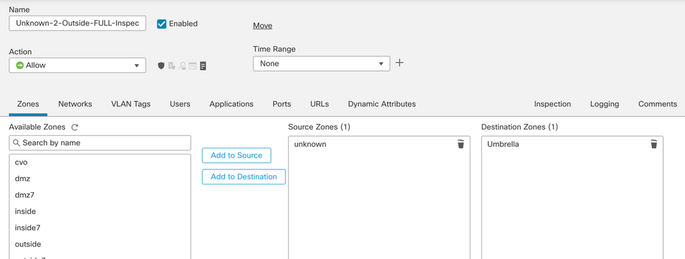
Create a new ACP rule like this:
-
- Source Zone – Internal Protected Source.
- Destination Zone – VTI Zone – This allows the traffic to be diverted to the VTI.
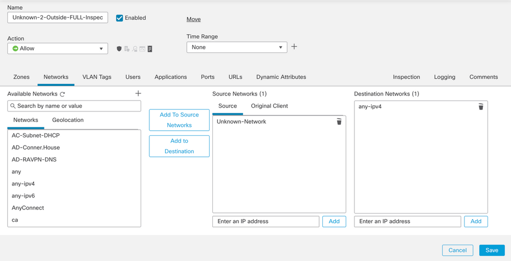
Networks:
-
- Source Networks - Internal protected network object(s)
- Destination Networks – any4 – 0.0.0.0/0
Save the configuration and deploy it to the Firewall.
Verify
Site-to-Site Monitoring
Verify tunnel status with the Secure Firewall Management Center (FMC) Site-to-Site Monitoring tool.
Navigate to Devices > Site to Site Monitoring.
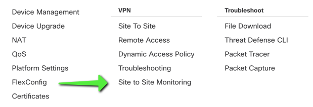
Verify that the tunnel status is now connected:

Hovering the cursor over the topology displays more detailed options. This can be used to inspect packets moving in and out of the tunnel along with tunnel up time and various other tunnel stats.
Umbrella Dashboard
From the Dashboard, navigate to Active Network Tunnels. There must be a blue ring indicating that the tunnel is connected.

Expand the appropriate tunnel in order to see more details about traffic flowing through the tunnel:
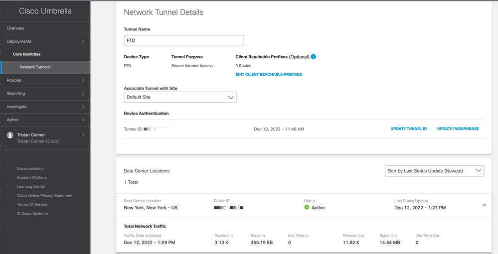
Tunnel showing as Active with data traversing the tunnel.
Internal Host
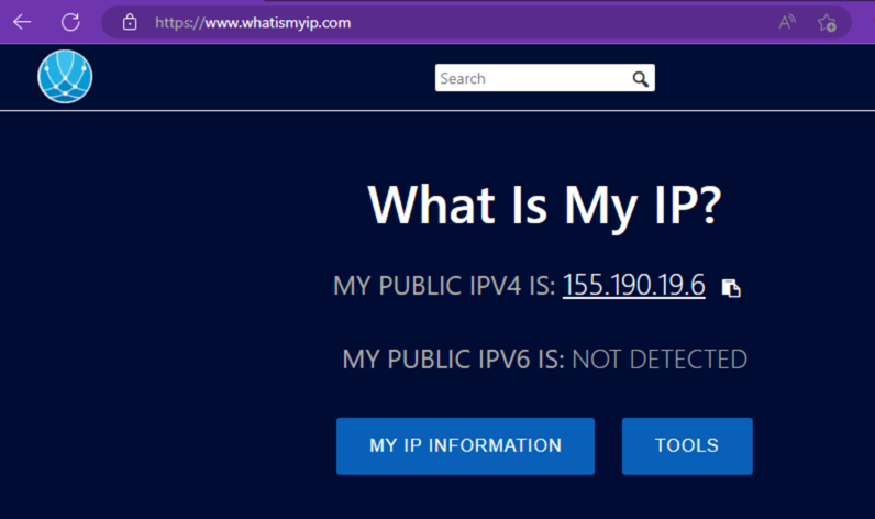
From an internal host that has its traffic traverse the tunnel, perform a public IP lookup from a web browser. If the public IP shown falls inside these two ranges, the device is now protected by SIG.
Firewall Threat Defense CLI
Show commands:
show crypto ikev2 sashow crypto ipsec sashow vpn-sessiondb l2l filter ipaddress Umbrella-DC-IP
Troubleshoot
Firewall Threat Defense CLI
IKEv2 Debugs:
Debug crypto ikev2 protocol 255Debug crypto ikev2 platform 255Debug crypto ipsec 255
ISAKMP Captures:
ISAKMP capture can be used in order to determine what is causing tunnel connectivity issues without the need for debugs. The suggested capture syntax is: capture name type isakmp interface FTD-Tunnel-Source match ip host FTD-Public-IP host Umbrella-DC-IP.


 Feedback