Configure Secure Firewall Device Manager in High Availability
Available Languages
Download Options
Bias-Free Language
The documentation set for this product strives to use bias-free language. For the purposes of this documentation set, bias-free is defined as language that does not imply discrimination based on age, disability, gender, racial identity, ethnic identity, sexual orientation, socioeconomic status, and intersectionality. Exceptions may be present in the documentation due to language that is hardcoded in the user interfaces of the product software, language used based on RFP documentation, or language that is used by a referenced third-party product. Learn more about how Cisco is using Inclusive Language.
Contents
Introduction
This document describes how to configure and verify Secure Firewall Device Manager (FDM) High Availability (HA) on Secure Firewall Devices.
Prerequisites
Requirements
Components Used
The information in this document is based on these software and hardware versions:
- 2xCisco Secure Firewall 2100 Security Appliance
- Running FDM version 7.0.5 (build 72)
The information in this document was created from the devices in a specific lab environment. All of the devices used in this document started with a cleared (default) configuration. If your network is live, ensure that you understand the potential impact of any command.
Task 1. Verify Conditions
Task requirement:
Verify that both FDM appliances meet the note requirements and can be configured as HA units.
Solution:
Step 1. Connect to the appliance Management IP using SSH and verify the module hardware.
Verify with the show version command the Primary device hardware and software version:
> show version
-------------------[ FPR2130-1 ]--------------------
Model : Cisco Firepower 2130 Threat Defense (77) Version 7.0.5 (Build 72)
UUID : 6197946e-2747-11ee-9b20-ead7c72f2631
VDB version : 338
----------------------------------------------------
Verify the Secondary Device hardware and software version:
> show version
-------------------[ FPR2130-2 ]--------------------
Model : Cisco Firepower 2130 Threat Defense (77) Version 7.0.5 (Build 72)
UUID : 6ba86648-2749-11ee-b7c9-c9e434a6c9ab
VDB version : 338
----------------------------------------------------
Task 2. Configure Secure Firewall Device Manager in High Availability
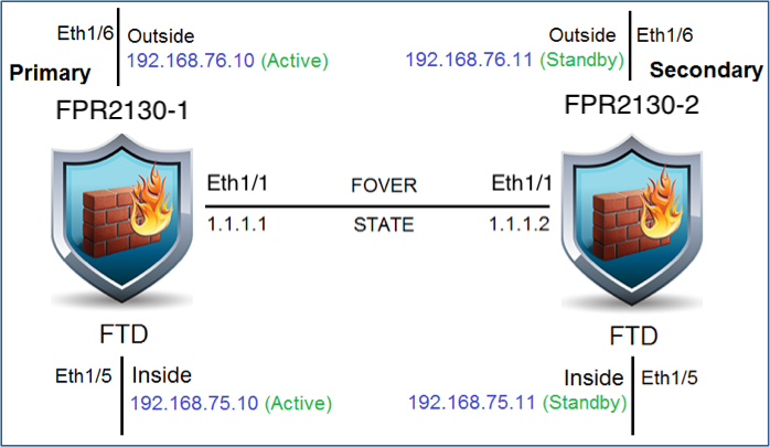
Network Diagram
Configure Active/Standby High Availability (HA) as per this diagram:
Enable High Availability on Secure Firewall Device Manager in Primary Unit
Step 1. In order to configure FDM Failover, navigate to Device and click Configure next to the High Availability group:

Step 2. On the High Availability page, click the Primary Device box:

Warning: Ensure to select the correct unit as the primary unit. All configurations on the selected primary unit are replicated to the selected secondary FTD unit. As a result of replication, the current configuration on the secondary unit can be replaced.
Step 3. Configure the failover link and the state link settings:
In this example, the state link has the same settings as the Failover link.
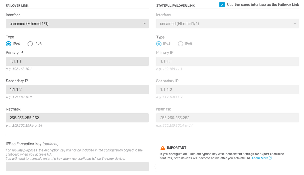
Step 4. Click on Activate HA
Step 5. Copy the HA configuration to the clipboard on the confirmation message, to paste it on the Secondary unit.
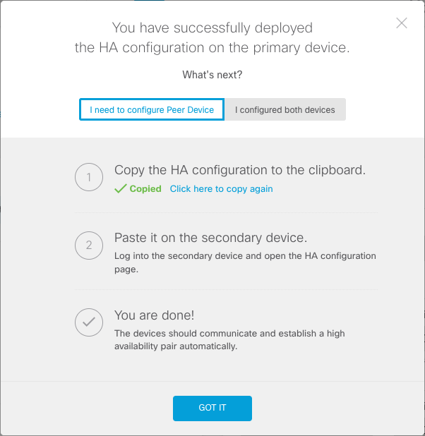
The system immediately deploys the configuration to the device. You do not need to start a deployment job. If you do not see a message saying that your configuration was saved and deployment is in progress, scroll to the top of the page to see the error messages.
The configuration is also copied to the clipboard. You can use the copy to quickly configure the secondary unit. For added security, the encryption key is not included in the clipboard copy.
At this point, you must be on the High Availability page, and your device status must be “Negotiating.” The status must transition to Active even before you configure the peer, which must appear as Failed until you configure it.

Enable High Availability on Secure Firewall Device Manager in Secondary Unit
After you configure the primary device for active/standby high availability, you must then configure the secondary device. Log into the FDM on that device and run this procedure.
Step 1. In order to configure FDM Failover, navigate to Device and click Configure next to the High Availability group:

Step 2. On the High Availability page, click the Secondary Device box:

Step 3. Choose one of these options:
-
Easy method—Click the Paste from Clipboard button, paste in the configuration, and click OK. This updates the fields with the appropriate values, which you can then verify.
-
Manual method—Configure the failover and stateful failover links directly. Enter the exact same settings on the secondary device that you entered on the primary device.
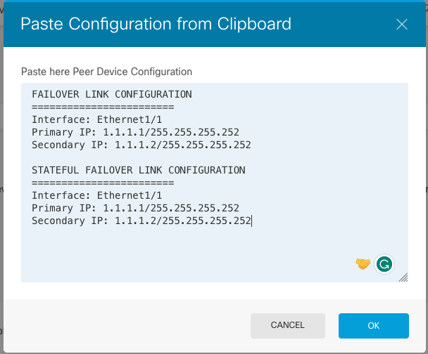
Step 4. Click Activate HA
The system immediately deploys the configuration to the device. You do not need to start a deployment job. If you do not see a message saying that your configuration was saved and deployment is in progress, scroll to the top of the page to see the error messages.
After the configuration completes, you get a message saying that you have configured HA. Click Got It to dismiss the message.
At this point, you must be on the High Availability page, and your device status must indicate that this is the secondary device. If the join with the primary device was successful, the device synchronize with the primary, and eventually, the mode must be Standby and the peer must be Active.

Complete The Interfaces Configuration
Step 1. In order to configure FDM Interfaces, navigate to Device and click View All Interfaces:
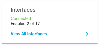
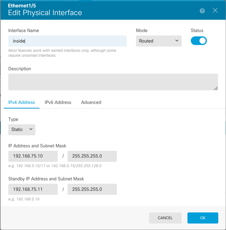
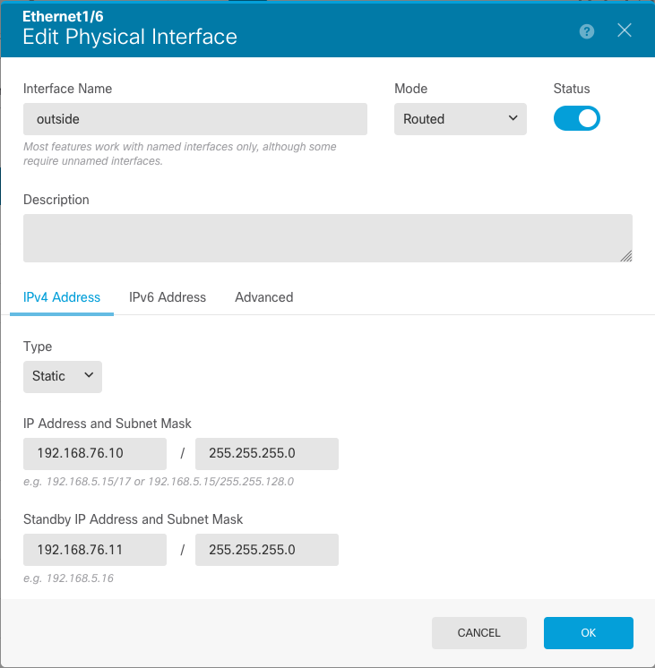
Step 2. Select and Edit the Interfaces settings as shown in the images:
Ethernet 1/5 Interface:
Ethernet 1/6 Interface
Step 3. After you configure the changes, click on Pending Changes and Deploy Now.
Task 3. Verify FDM High Availability
Task requirement:
Verify the High Availability settings from the FDM GUI and from FDM CLI.
Solution:
Step 1. Navigate to Device and check the High Availability settings:
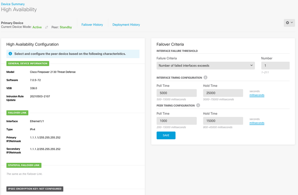
Step 2. Connect to the FDM Primary Device CLI using SSH and validate with the show high-availability config command:
> show high-availability config
Failover On
Failover unit Primary
Failover LAN Interface: failover-link Ethernet1/1 (up)
Reconnect timeout 0:00:00
Unit Poll frequency 1 seconds, holdtime 15 seconds
Interface Poll frequency 5 seconds, holdtime 25 seconds
Interface Policy 1
Monitored Interfaces 4 of 1293 maximum
MAC Address Move Notification Interval not set
failover replication http
Version: Ours 9.16(4)200, Mate 9.16(4)200
Serial Number: Ours JAD231510ZT, Mate JAD2315110V
Last Failover at: 00:01:29 UTC Jul 25 2023
        This host: Primary - Active
                Active time: 4927 (sec)
                slot 0: FPR-2130 hw/sw rev (1.3/9.16(4)200) status (Up Sys)
                  Interface diagnostic (0.0.0.0): Normal (Waiting)
                  Interface eth2 (0.0.0.0): Link Down (Shutdown)
                  Interface inside (192.168.75.10): No Link (Waiting)
                  Interface outside (192.168.76.10): No Link (Waiting)
                slot 1: snort rev (1.0)  status (up)
                slot 2: diskstatus rev (1.0)  status (up)
        Other host: Secondary - Standby Ready
                Active time: 0 (sec)
                slot 0: FPR-2130 hw/sw rev (1.3/9.16(4)200) status (Up Sys)
                  Interface diagnostic (0.0.0.0): Normal (Waiting)
                  Interface eth2 (0.0.0.0): Link Down (Shutdown)
                  Interface inside (192.168.75.11): No Link (Waiting)
                  Interface outside (192.168.76.11): No Link (Waiting)
                slot 1: snort rev (1.0)  status (up)
                slot 2: diskstatus rev (1.0)  status (up)

Stateful Failover Logical Update Statistics
        Link : failover-link Ethernet1/1 (up)
        Stateful Obj    xmit       xerr       rcv        rerr
        General         189        0          188        0
        sys cmd         188        0          188        0
        up time         0          0          0          0
        RPC services    0          0          0          0
        TCP conn        0          0          0          0
        UDP conn        0          0          0          0
        ARP tbl         0          0          0          0
        Xlate_Timeout   0          0          0          0
        IPv6 ND tbl     0          0          0          0
        VPN IKEv1 SA    0          0          0          0
        VPN IKEv1 P2    0          0          0          0
        VPN IKEv2 SA    0          0          0          0
        VPN IKEv2 P2    0          0          0          0
        VPN CTCP upd    0          0          0          0
        VPN SDI upd     0          0          0          0
        VPN DHCP upd    0          0          0          0
        SIP Session     0          0          0          0
        SIP Tx  0          0          0          0
        SIP Pinhole     0          0          0          0
        Route Session   0          0          0          0
        Router ID       0          0          0          0
        User-Identity   1          0          0          0
        CTS SGTNAME     0          0          0          0
        CTS PAC         0          0          0          0
        TrustSec-SXP    0          0          0          0
        IPv6 Route      0          0          0          0
        STS Table       0          0          0          0
        Rule DB B-Sync  0          0          0          0
        Rule DB P-Sync  0          0          0          0
        Rule DB Delete  0          0          0          0

        Logical Update Queue Information
                        Cur     Max     Total
        Recv Q:         0       10      188
        Xmit Q:         0       11      957
Step 3. Do the same on the Secondary device.
Step 4. Validate the current state with the show failover state command:
> show failover state

               State          Last Failure Reason      Date/Time
This host  -   Primary
               Active         None
Other host -   Secondary
               Standby Ready  Comm Failure             00:01:45 UTC Jul 25 2023

====Configuration State===
        Sync Done
====Communication State===
        Mac set
Step 5. Verify the configuration from the Primary unit with the show running-config failover and show running-config interface:
> show running-config failover
failover
failover lan unit primary
failover lan interface failover-link Ethernet1/1
failover replication http
failover link failover-link Ethernet1/1
failover interface ip failover-link 1.1.1.1 255.255.255.252 standby 1.1.1.2

> show running-config interface
!
interface Ethernet1/1
 description LAN/STATE Failover Interface
 ipv6 enable
!
interface Ethernet1/2
 shutdown
 no nameif
 no security-level
 no ip address
!
interface Ethernet1/3
 shutdown
 no nameif
 no security-level
 no ip address
!
interface Ethernet1/4
 shutdown
 no nameif
 no security-level
 no ip address
!
interface Ethernet1/5
 nameif inside
 security-level 0
 ip address 192.168.75.10 255.255.255.0 standby 192.168.75.11
!
interface Ethernet1/6
 nameif outside
 security-level 0
 ip address 192.168.76.10 255.255.255.0 standby 192.168.76.11
!
interface Ethernet1/7
 shutdown
 no nameif
 no security-level
 no ip address
!
interface Management1/1
 management-only
 nameif diagnostic
 cts manual
  propagate sgt preserve-untag
  policy static sgt disabled trusted
 security-level 0
 no ip address
Task 4. Switch the Failover Roles
Task requirement:
From the Secure Firewall Device Manager Graphic Interface, switch the failover roles from Primary/Active, Secondary/Standby to Primary/Standby, Secondary/Active
Solution:
Step 1. Click on Device

Step 2. Click the High Availability link on the right side of the device summary.

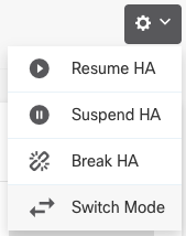
Step 3. From the gear icon ( ), choose Switch Mode.
Step 4. Read the confirmation message and click OK.
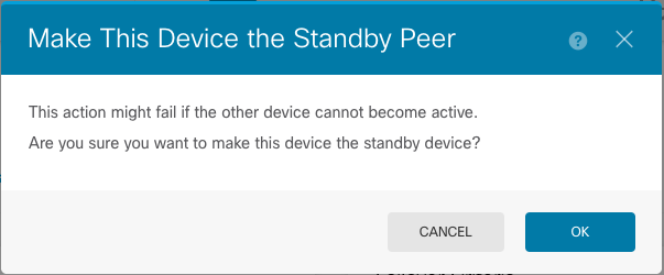
The system forces failover so that the active unit becomes standby, and the standby unit becomes the new active unit.
Step 5. Verify the result as shown in the image:

Step 6. It is also possible to verify using the Failover History link and the CLI Console pop-up must show the results:
==========================================================================
From State                 To State                   Reason
==========================================================================
21:55:37 UTC Jul 20 2023
Not Detected               Disabled                   No Error

00:00:43 UTC Jul 25 2023
Disabled                   Negotiation                Set by the config command

00:01:28 UTC Jul 25 2023
Negotiation                Just Active                No Active unit found

00:01:29 UTC Jul 25 2023
Just Active                Active Drain               No Active unit found

00:01:29 UTC Jul 25 2023
Active Drain               Active Applying Config     No Active unit found

00:01:29 UTC Jul 25 2023
Active Applying Config     Active Config Applied      No Active unit found

00:01:29 UTC Jul 25 2023
Active Config Applied      Active                     No Active unit found

18:51:40 UTC Jul 25 2023
Active                     Standby Ready              Set by the config command

==========================================================================
PEER History Collected at 18:55:08 UTC Jul 25 2023
===========================PEER-HISTORY===================================
From State                 To State                   Reason
===========================PEER-HISTORY===================================
22:00:18 UTC Jul 24 2023
Not Detected               Disabled                   No Error

00:52:08 UTC Jul 25 2023
Disabled                   Negotiation                Set by the config command

00:52:10 UTC Jul 25 2023
Negotiation                Cold Standby               Detected an Active mate

00:52:11 UTC Jul 25 2023
Cold Standby               App Sync                   Detected an Active mate

00:53:26 UTC Jul 25 2023
App Sync                   Sync Config                Detected an Active mate

01:00:12 UTC Jul 25 2023
Sync Config                Sync File System           Detected an Active mate

01:00:12 UTC Jul 25 2023
Sync File System           Bulk Sync                  Detected an Active mate

01:00:23 UTC Jul 25 2023
Bulk Sync                  Standby Ready              Detected an Active mate

18:45:01 UTC Jul 25 2023
Standby Ready              Just Active                Other unit wants me Active

18:45:02 UTC Jul 25 2023
Just Active                Active Drain               Other unit wants me Active

18:45:02 UTC Jul 25 2023
Active Drain               Active Applying Config     Other unit wants me Active

18:45:02 UTC Jul 25 2023
Active Applying Config     Active Config Applied      Other unit wants me Active

18:45:02 UTC Jul 25 2023
Active Config Applied      Active                     Other unit wants me Active

===========================PEER-HISTORY===================================
Step 7. After the verification, make the Primary unit Active again.
Task 5. Suspending or Resuming High Availability
You can suspend a unit in a high availability pair. This is useful when:
-
Both units are in an active-active situation and fixing the communication on the failover link does not correct the problem.
-
You want to troubleshoot an active or standby unit and do not want the units to fail over during that time.
-
You want to prevent failover while installing a software upgrade on the standby device.
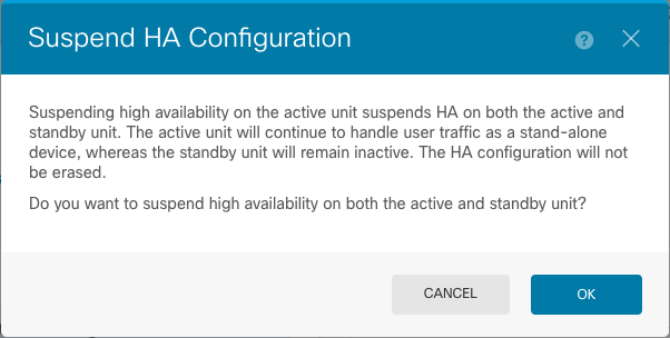
The key difference between suspending HA and breaking HA is that on a suspended HA device, the high availability configuration is retained. When you break HA, the configuration is erased. Thus, you have the option to resume HA on a suspended system, which enables the existing configuration and makes the two devices function as a failover pair again.
Task requirement:
From the Secure Firewall Device Manager Graphic Interface, suspend the Primary unit and Resume High Availability on the same unit.
Solution:
Step 1. Click Device.

Step 2. Click the High Availability link on the right side of the device summary.

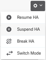
Step 3. From the gear icon ( ), choose Suspend HA.
Step 4. Read the confirmation message and click OK.
Step 5. Verify the result as shown in the image:

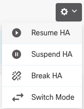
Step 6. To Resume the HA, from the gear icon ( ), choose Resume HA.
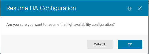
Step 7. Read the confirmation message and click OK.
Step 5. Verify the result as shown in the image:

Task 6. Breaking High Availability
If you no longer want the two devices to operate as a high-availability pair, you can break the HA configuration. When you break HA, each device becomes a standalone device. Their configurations must change as:
-
The active device retains the full configuration as it is prior to the break, with the HA configuration removed.
-
The standby device has all interface configurations removed in addition to the HA configuration. All physical interfaces are disabled, although subinterfaces are not disabled. The management interface remains active, so you can log into the device and reconfigure it.
Task requirement:
From the Secure Firewall Device Manager Graphic Interface, break the High Availability pair.
Solution:
Step 1. Click Device.

Step 2. Click the High Availability link on the right side of the device summary.

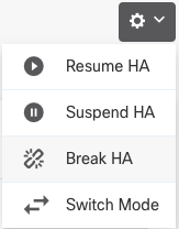
Step 3. From the gear icon ( ), choose Break HA.
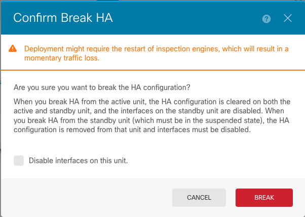
Step 4. Read the confirmation message, decide whether to select the option to disable interfaces, and click Break.
You must select the option to disable interfaces if you are breaking HA from the standby unit.
The system immediately deploys your changes on both this device and the peer device (if possible). It can take a few minutes for deployment to complete on each device and for each device to become independent.
Step 5. Verify the result as shown in the image:

Related Information
- All versions of the Cisco Secure Firewall Device Manager configuration guide can be found here
- Cisco Global Technical Assistance Center (TAC) strongly recommends this visual guide for in-depth practical knowledge on Cisco Firepower Next-Generation Security Technologies:
https://www.ciscopress.com/store/cisco-firepower-threat-defense-ftd-configuration-and-9781587144806
- For all Configuration and Troubleshoot TechNotes that pertain to the Firepower technologies
https://www.cisco.com/c/en/us/support/security/defense-center/series.html
Revision History
| Revision | Publish Date | Comments |
|---|---|---|
1.0 |
27-Jul-2023 |
Initial Release |
Contributed by Cisco Engineers
- Armando Lozada AlcantarSecurity Escalation Engineer
Contact Cisco
- Open a Support Case

- (Requires a Cisco Service Contract)
 Feedback