L2 Switch on FPR1010, Architecture, Verification and Troubleshooting
Available Languages
Download Options
Bias-Free Language
The documentation set for this product strives to use bias-free language. For the purposes of this documentation set, bias-free is defined as language that does not imply discrimination based on age, disability, gender, racial identity, ethnic identity, sexual orientation, socioeconomic status, and intersectionality. Exceptions may be present in the documentation due to language that is hardcoded in the user interfaces of the product software, language used based on RFP documentation, or language that is used by a referenced third-party product. Learn more about how Cisco is using Inclusive Language.
Contents
Introduction
This document describes the L2 switch on FP1010 devices. Specifically, it covers mainly the Security Services Platform (SSP)/Firepower eXtensive Operation System (FXOS) part of the implementation. In the 6.5 release, the Firepower 1010 (Desktop model) enabled switching capabilities on the built-in L2 hardware switch. This helps you to avoid extra hardware switches and the cost is reduced.
Prerequisites
Requirements
There are no specific requirements for this document.
Components Used
The information in this document was created from the devices in a specific lab environment. All of the devices used in this document started with a cleared (default) configuration. If your network is live, ensure that you understand the potential impact of any command.
Background Information
- FP1010 is a desktop model Small-Office Home-Office (SOHO) which comes as a replacement for ASA5505 and ASA5506-X platforms.
- Software support for FTD images (6.4+) managed by either Firepower Management Center (FMC), Firepower Device Manager (FDM), or Cloud Defense Orchestrator (CDO).
- Software support for ASA images (9.13+) managed by either CSM, ASDM, or CLI.
- The Operating System (OS), ASA or FTD, is FXOS bundled (similar to FP21xx).
- 8 x 10/100/1000 Mbps data ports.
- Ports E1/7, E1/8 support PoE+.
- Hardware switch allows line rate communication between ports (e.g: a camera feed into the local server).

Firepower 6.5 Additions
- Introduction of a new type of Interface called Switched Virtual Interface (SVI).
- Mixed Mode: Interfaces can be configured in either switched (L2) or non-switched (L3) mode.
- L3 mode interfaces forwards all packets to the security application.
- L2 mode ports can switch in hardware if two ports are part of the same VLAN which improves throughput and latency. And packets that need to be routed or bridged reach the security application (e.g: a camera downloading a new firmware from the Internet) and undergo security inspection as per the configuration.
- L2 physical interface can be associated with one or multiple SVI interfaces.
- L2 mode interfaces can be in access or trunk mode.
- Access mode L2 interface allows only untagged traffic.
- Trunk mode L2 interface allows tagged traffic.
- Native VLAN support for trunk mode L2 interface.
- ASA CLIs, ASDM, CSM, FDM, FMC are enhanced to support new features.
FMC Additions
- A new interface mode called switchport has been introduced for a physical interface which is used to identify if a physical interface is an L3 or L2 interface.
- L2 physical interface can be associated with one or multiple VLAN interfaces based on access or trunk mode.
- Firepower 1010 supports Power Over Ethernet (PoE) configuration on the last two data interfaces i.e. Ethernet1/7 and Ethernet1/8.
- Interface change between switched and non-switched clears all the configurations except the PoE and Hardware configuration.
How It Works
This feature is just an enhancement of existing Interface support on FMC (Device Management > Interface Page).

Physical Interface view (L2 and L3)

FP1010 Architecture
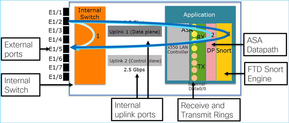
- 8 External Data ports.
- 1 Internal Switch.
- 3 Uplink ports (2 of them shown in the picture), one for Data-Plane, one for Control-Plane, one for Configuration.
- x550 LAN Controller (the interface between the application and the uplinks).
- 4 Receive (RX) and 4 Transmit (TX) rings.
- Datapath process (on ASA and FTD).
- Snort process (on FTD).
Packet Processing
Two main factors can affect packet processing:
1. Interface/port mode
2. Applied policy
A packet can traverse an FP1010 in 3 different ways:
1. Only processed by the internal switch
2. Forwarded up to the application (ASA/FTD) and processed by the datapath process only
3. Forwarded up to the application (FTD) and processed by the datapath and Snort engine
FP1010 Port Modes
The UI examples are for FMC, the CLI examples are for FTD. Most of the concepts are also fully applicable to an ASA.
FP1010 Case 1. Routed Ports (IP Routing)
Configuration and Operation

Key Points
- From a design point of view, the 2 ports belong to 2 different L2 subnets.
- When the ports are configured in Routed mode, the packets are processed by the application (ASA or FTD).
- In the case of FTD, based on the rule action (e.g. ALLOW), the packets can be even inspected by the Snort engine.
FTD interface configuration
interface Ethernet1/3
 nameif NET203
 cts manual
  propagate sgt preserve-untag
  policy static sgt disabled trusted
 security-level 0
 ip address 10.10.203.2 255.255.255.0
!
interface Ethernet1/4
 nameif NET204
 cts manual
  propagate sgt preserve-untag
  policy static sgt disabled trusted
 security-level 0
 ip address 10.10.204.2 255.255.255.0
FP1010 Routed Port Verification
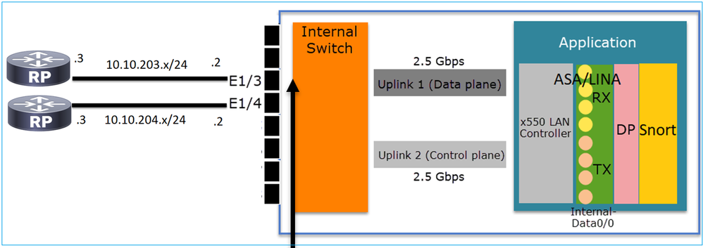
From FXOS CLI you can check the physical interface counters. This example shows the ingress unicast and egress unicast counters on the E1/3 port:
FP1010(local-mgmt)# show portmanager counters ethernet 1 3 | egrep "stats.ing_unicastframes\|stats.egr_unicastframes"
stats.ing_unicastframes        = 3521254
stats.egr_unicastframes        = 604939
FTD datapath captures can be applied and packets can be traced:
FP1010# show capture
capture CAP203 type raw-data trace interface NET203 [Capturing - 185654 bytes]
This is a capture snippet. As expected, the packet is forwarded based on a ROUTE LOOKUP:
FP1010# show capture CAP203 packet-number 21 trace

21: 06:25:23.924848       10.10.203.3 > 10.10.204.3 icmp: echo request
…
Phase: 3
Type: ROUTE-LOOKUP
Subtype: Resolve Egress Interface
Result: ALLOW
Config:
Additional Information:
found next-hop 10.10.204.3 using egress ifc  NET204
FP1010 Case 2. Bridge-Group mode (Bridging)
Configuration and Operation


Key Points
- From a design point of view, the 2 ports are connected to the same L3 subnet (similar to a transparent firewall), but different VLAN.
- When the ports are configured in Bridging mode, the packets are processed by the application (ASA or FTD).
- In the case of FTD, based on the rule action (e.g. ALLOW), the packets can be even inspected by the Snort engine.
FTD interface configuration
interface Ethernet1/3
 bridge-group 34
 nameif NET203
 cts manual
  propagate sgt preserve-untag
  policy static sgt disabled trusted
 security-level 0
!
interface Ethernet1/4
 bridge-group 34
 nameif NET204
 cts manual
  propagate sgt preserve-untag
  policy static sgt disabled trusted
 security-level 0
!
interface BVI34
 nameif NET34
 security-level 0
 ip address 10.10.203.1 255.255.255.0
FP1010 Bridge-Group Port Verification
This command shows the interface members of BVI 34:
FP1010# show bridge-group 34
 Interfaces:
 Ethernet1/3
 Ethernet1/4
 Management System IP Address:  10.10.203.1 255.255.255.0
 Management Current IP Address: 10.10.203.1 255.255.255.0
 Management IPv6 Global Unicast Address(es):    N/A
 Static mac-address entries:  0
 Dynamic mac-address entries: 13
This command shows the ASA/FTD datapath Content Addressable Memory (CAM) table:
FP1010# show mac-address-table
interface                  mac  address     type       Age(min)    bridge-group
------------------------------------------------------------------
NET203                     0050.5685.43f1   dynamic      1             34
NET204                     4c4e.35fc.fcd8   dynamic      3             34
NET203                     0050.56b6.2304   dynamic      1             34
NET204                     0017.dfd6.ec00   dynamic      1             34
NET203                     0050.5685.4fda   dynamic      1             34
A packet trace snippet shows that the packet is forwarded based on Destination MAC L2 Lookup:
FP1010# show cap CAP203 packet-number 1 trace

2 packets captured

1: 11:34:40.277619 10.10.203.3 > 10.10.203.4 icmp: echo request
Phase: 1
Type: L2-EGRESS-IFC-LOOKUP
Subtype: Destination MAC L2 Lookup
Result: ALLOW
Config:
Additional Information:
DestinationMAC lookup resulted in egress ifc NET204
In the case of FTD, FMC Connection Events can also provide information about the flow inspection and the transit bridge-group interfaces:

FP1010 Case 3. Switchports (HW switching) in Access Mode
Configuration and Operation
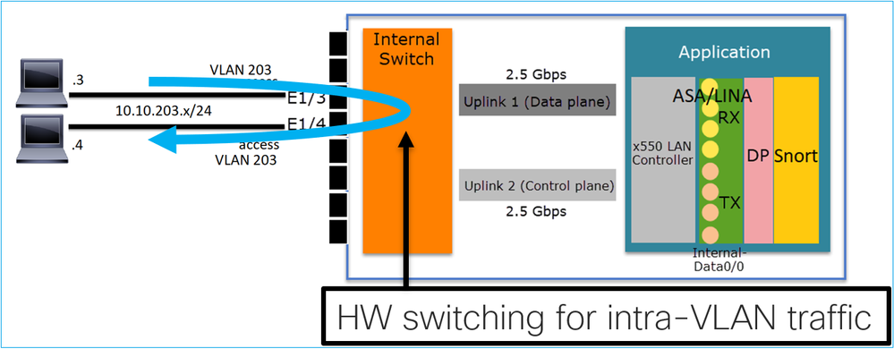

Key Points
- HW Switching is an FTD 6.5+ and ASA 9.13+ feature.
- From a design point of view, the 2 ports are connected to the same L3 subnet and the same VLAN.
- The ports in this scenario are operating in Access mode (untagged traffic only).
- The firewall ports configured in SwitchPort mode do not have a logical name (nameif) configured.
- When the ports are configured in Switching mode and belong to the same VLAN (intra-VLAN traffic) the packets are processed by the FP1010 internal switch only.
FTD interface configuration
From a CLI point of view, the configuration looks very similar to a L2 switch:
interface Ethernet1/3
 switchport
 switchport access vlan 203
!
interface Ethernet1/4
 switchport
 switchport access vlan 203
Filtering Intra-VLAN Traffic
The challenge: An ACL cannot filter intra-VLAN traffic!
The solution: Protected ports
The principle is very simple: 2 ports that are configured as Protected cannot talk to each other.
FMC UI in case of Protected ports:

FTD interface configuration
The command switchport protected is configured under the interface:
interface Ethernet1/3
 switchport
 switchport access vlan 203
 switchport protected
!
interface Ethernet1/4
 switchport
 switchport access vlan 203
 switchport protected
FP1010 Switchport Verification
In this example, there are 1000 unicast packets (ICMP) sent with a specific size (1100 Bytes):
router# ping 10.10.203.4 re 1000 timeout 0 size 1100
To check the ingress and egress unicast counters of the transit interfaces use this command:
FP1010(local-mgmt)# show portmanager counters ethernet 1 3 | egrep "stats.ing_unicastframes\|stats.bytes_1024to1518_frames"
stats.ing_unicastframes        = 146760
stats.bytes_1024to1518_frames  = 0
FP1010(local-mgmt)# show portmanager counters ethernet 1 4 | egrep "stats.egr_unicastframes\|stats.bytes_1024to1518_frames"
stats.bytes_1024to1518_frames  = 0
stats.egr_unicastframes        = 140752
FP1010(local-mgmt)# show portmanager counters ethernet 1 3 | egrep "stats.ing_unicastframes\|stats.bytes_1024to1518_frames"
stats.ing_unicastframes        = 147760                         <------------------ Ingress Counters got increased by 1000
stats.bytes_1024to1518_frames  = 1000                           <------------------ Ingress Counters got increased by 1000
FP1010(local-mgmt)# show portmanager counters ethernet 1 4 | egrep "stats.egr_unicastframes\|stats.bytes_1024to1518_frames"
stats.bytes_1024to1518_frames  = 0                              <------------------ No egress increase
stats.egr_unicastframes        = 140752                         <------------------ No egress increase
This command shows the Internal switch VLAN status:
FP1010# show switch vlan
VLAN Name           Status    Ports
---- -------------- --------- ----------------------
1     -             down
203   -             up        Ethernet1/3, Ethernet1/4
The status of a VLAN is UP as long as at least one port is assigned to the VLAN
If a port is administratively down or the connected switch port is down/cable disconnected and this is the only port assigned to the VLAN, the VLAN status is also down:
FP1010-2# show switch vlan
VLAN Name                             Status    Ports
---- -------------------------------- --------- -----------------------------
1    -                                down
201  net201                           down      Ethernet1/1          <--- e1/1 was admin down
202  net202                           down      Ethernet1/2          <--- upstream switch port is admin down
This command shows the CAM table of the internal switch:
FP1010-2# show switch mac-address-table
Legend: Age - entry expiration time in seconds

   Mac Address  | VLAN |            Type          | Age | Port
-------------------------------------------------------------
 4c4e.35fc.0033 | 0203 |          dynamic         | 282 | Et1/3
 4c4e.35fc.4444 | 0203 |          dynamic         | 330 | Et1/4
The internal switch CAM table default aging time is 5min 30 sec.
FP1010 contains 2 CAM tables:
- Internal Switch CAM table: Used in case of HW switching
- ASA/FTD datapath CAM table: Used in case of Bridging
Each packet/frame that traverses the FP1010 is processed by a single CAM table (internal switch or FTD datapath) based on the port mode.
Caution: Do not confuse the show switch mac-address-table internal switch CAM table used in SwitchPort mode with the show mac-address-table FTD datapath CAM table used in bridged mode
HW Switching: Additional things to be aware of
ASA/FTD datapath logs do not show information about HW-switched flows:
FP1010# show log
FP1010#
ASA/FTD datapath connection table does not show HW-switched flows:
FP1010# show conn
0 in use, 3 most used
Inspect Snort:
        preserve-connection: 0 enabled, 0 in effect, 0 most enabled, 0 most in effect
Additionally, the FMC Connection Events do not show HW-switched flows.
FP1010 Case 4. Switchports (Trunking)
Configuration and Operation
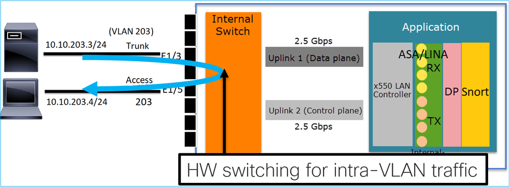

Key Points
- HW Switching is an FTD 6.5+ and ASA 9.13+ feature.
- From a design point of view, the 2 ports are connected to the same L3 subnet and the same VLAN.
- Trunk port accepts Tagged frames and untagged (in case of a native VLAN).
- When the ports are configured in Switching mode and belong to the same VLAN (intra-VLAN traffic) the packets are processed by the internal switch only.
FTD interface configuration
The configuration is similar to a layer 2 switch port:
interface Ethernet1/3
 switchport
 switchport trunk allowed vlan 203
 switchport trunk native vlan 1
 switchport mode trunk
!
interface Ethernet1/5
 switchport
 switchport access vlan 203
FP1010 Case 5. Switchports (Inter-VLAN)
Configuration and Operation
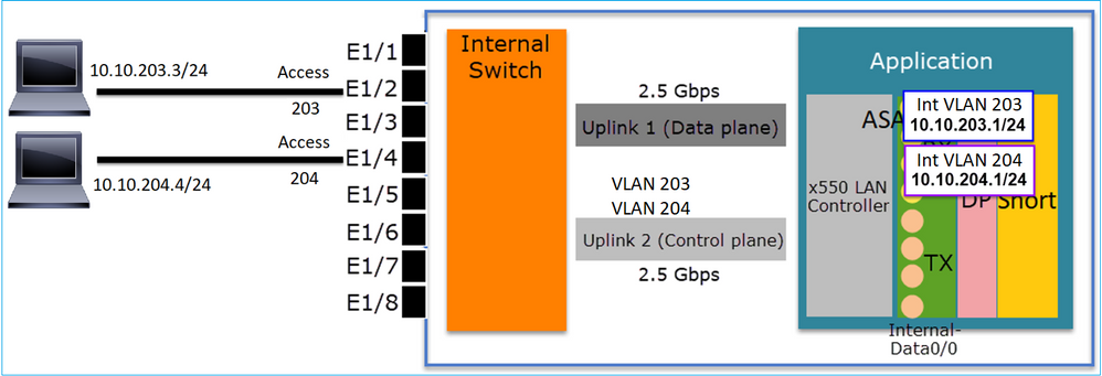

Key Points
- From a design point of view, the 2 ports are connected to 2 different L3 subnets and 2 different VLANs.
- Traffic between the VLANs goes through the VLAN interfaces (similar to SVIs).
- From a traffic flow point of view, inter-VLAN traffic reaches the application.
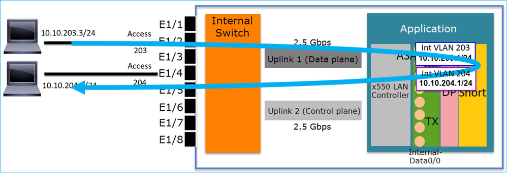
FTD interface configuration
The configuration is similar to a Switch Virtual Interface (SVI):
interface Ethernet1/2
 switchport
 switchport access vlan 203
interface Ethernet1/4
 switchport
 switchport access vlan 204
!
interface Vlan203
 nameif NET203
 security-level 0
 ip address 10.10.203.1 255.255.255.0
interface Vlan204
 nameif NET204
 security-level 0
 ip address 10.10.204.1 255.255.255.0
Packet Processing for inter-VLAN traffic
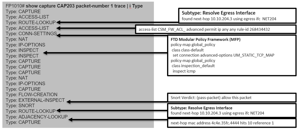
This is a trace of a packet that traverses through 2 different VLANs:
FP1010# show capture CAP203 packet-number 1 trace | include Type
Type: CAPTURE
Type: ACCESS-LIST
Type: ROUTE-LOOKUP
Type: ACCESS-LIST
Type: CONN-SETTINGS
Type: NAT
Type: IP-OPTIONS
Type: INSPECT
Type: INSPECT
Type: CAPTURE
Type: CAPTURE
Type: CAPTURE
Type: NAT
Type: IP-OPTIONS
Type: CAPTURE
Type: FLOW-CREATION
Type: EXTERNAL-INSPECT
Type: SNORT
Type: ROUTE-LOOKUP
Type: ADJACENCY-LOOKUP
Type: CAPTURE
The main phases in the packet process:
FP1010 Case 6. Inter-VLAN filter
Configuration and Operation
There are 2 main options to filter inter-VLAN traffic:
- Access Control Policy
- ‘no forward’ command
Filter inter-VLAN traffic with the use of the 'no forward' command
FMC UI configuration:

Key Points
- The no forward drop is unidirectional.
- It cannot be applied to both VLAN interfaces.
- The no forward check is done before the ACL check.
FTD interface configuration
The CLI configuration in this case is:
interface Vlan203
 no forward interface Vlan204
 nameif NET203
 security-level 0
 ip address 10.10.203.1 255.255.255.0
!
interface Vlan204
 nameif NET204
 security-level 0
 ip address 10.10.204.1 255.255.255.0
If a packet is dropped by the no forward feature an ASA/FTD datapath Syslog message is generated:
FP1010# show log
Sep 10 2019 07:44:54: %FTD-5-509001: Connection attempt was prevented by "no forward" command: icmp src NET203:10.10.203.3 dst NET204:10.10.204.3 (type 8, code 0)
From the Accelerated Security Path (ASP) drop point of view, it is considered an ACL drop:
FP1010-2# show asp drop
Frame drop:
  Flow is denied by configured rule (acl-drop)                        1
Since the drop is unidirectional, Host-A (VLAN 203) cannot initiate traffic to Host-B (VLAN 204), but the opposite is allowed:

Case Study - FP1010. Bridging vs HW Switching + Bridging
Consider the following topology:
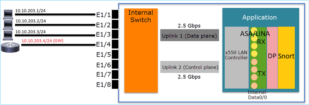
In this topology:
- Three end-hosts belong to the same L3 subnet (10.10.203.x/24).
- The router (10.10.203.4) acts as a GW in the subnet.
In this topology there are 2 main design options:
- Bridging
- HW Switching + Bridging
Design Option 1. Bridging

Key Points
The main points of this design are:
- There is BVI 1 created with an IP in the same subnet (10.10.203.x/24) as the 4 attached devices.
- All four ports belong to the same Bridge-Group (group 1 in this case).
- Each of the four ports has a name configured.
- Host-to-host and host-to-GW communication goes through the application (e.g. FTD).
From the FMC UI point of view the configuration is:

FTD interface configuration
The configuration in this case is:
interface BVI1
 nameif BG1
 security-level 0
 ip address 10.10.203.100 255.255.255.0
interface Ethernet1/1
 no switchport
 bridge-group 1
 nameif HOST1
interface Ethernet1/2
 no switchport
 bridge-group 1
 nameif HOST2
interface Ethernet1/3
 no switchport
 bridge-group 1
 nameif HOST3
interface Ethernet1/4
 no switchport
 bridge-group 1
 nameif HOST4
The traffic flow in this scenario:

Design Option 2. HW Switching + Bridging

Key Points
The main points of this design are:
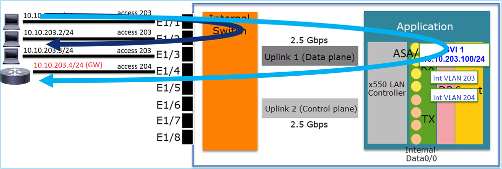
- There is BVI 1 created with an IP in the same subnet (10.10.203.x/24) as the 4 attached devices.
- The ports attached to the end-hosts are configured in SwitchPort mode and belong to the same VLAN (203).
- The port attached to the GW is configured in SwitchPort mode and belongs to a different VLAN (204).
- There are 2 VLAN interfaces (203, 204). The 2 VLAN interfaces do not have an IP assigned and belong to Bridge-Group 1.
- Host-to-host communication goes through the internal switch only.
- Host-to-GW communication goes through the application (e.g. FTD).
FMC UI config:

FTD interface configuration
The configuration in this case is:
interface Ethernet1/1
 switchport
 switchport access vlan 203
interface Ethernet1/2
 switchport
 switchport access vlan 203
interface Ethernet1/4
 switchport
 switchport access vlan 204
!
interface Vlan203
 bridge-group 1
 nameif NET203
interface Vlan204
 bridge-group 1
 nameif NET204
!
interface BVI1
 nameif BG1
 ip address 10.10.203.100 255.255.255.0
Host-to-host communication vs host-to-GW communication:
FP1010 Design Considerations
Switching and High Availability (HA)

There are 2 main problems when HW Switching is configured in an HA environment:
- HW Switching on the Standby unit forwards packets through the device. This can cause traffic loops.
- SwitchPorts are not monitored by HA
Design Requirement
- You must not use the SwitchPort functionality with ASA/FTD High Availability. This is documented in the FMC configuration guide:
https://www.cisco.com/c/en/us/td/docs/security/firepower/670/configuration/guide/fpmc-config-guide-v67/regular_firewall_interfaces_for_firepower_threat_defense.html#topic_kqm_dgc_b3b

Interaction with Spanning Tree Protocol (STP)
The FP1010 internal switch does not run STP.
Consider this scenario:

On the Edge Switch, the Root Port for both VLANs is G2/1:
Edge-Switch# show spanning-tree root | i 300|301
VLAN0300         33068 0017.dfd6.ec00         4    2   20  15  Gi2/1
VLAN0301         33069 0017.dfd6.ec00         4    2   20  15  Gi2/1
Connect an FP1010 to the edge switch and configure both ports in the same VLAN (HW Switching):

The Problem
- Due to VLAN leaking superior BPDUs for VLAN 301 received on G3/22
Edge-Switch# show spanning-tree root | in 300|301
VLAN0300         33068 0017.dfd6.ec00         4    2   20  15  Gi2/1
VLAN0301         33068 0017.dfd6.ec00         8    2   20  15  Gi3/22
Warning: If you connect an L2 switch to FP1010 you can affect the STP domain
This is also documented in the FMC configuration guide:

FXOS REST APIs
FMC REST APIs
These are the REST API(s) for this feature support:
- L2 Physical Interafce [Supported PUT/GET]
/api/fmc_config/v1/domain/{domainUUID}/devices/devicerecords/{containerUUID}/physicalinterfaces/{objectId}
- VLAN Interface [Supported POST/PUT/GET/DELETE]
/api/fmc_config/v1/domain/{domainUUID}/devices/devicerecords/{containerUUID}/vlaninterfaces/{objectId}
Troubleshooting/Diagnostics
Overview of Diagnostics
- Log files are captured in an FTD/NGIPS Troubleshoot or in the show tech output. These are the items that need to be looked for more details in case of troubleshooting:
- /opt/cisco/platform/logs/portmgr.out
- /var/sysmgr/sam_logs/svc_sam_dme.log
- /var/sysmgr/sam_logs/svc_sam_portAG.log
- /var/sysmgr/sam_logs/svc_sam_appAG.log
- Asa running-config
- /mnt/disk0/log/asa-appagent.log
Collect data from FXOS (device) – CLI
In the case of FTD (SSH):
> connect fxos
Cisco Firepower Extensible Operating System (FX-OS) Software
TAC support: http://www.cisco.com/tac
Copyright (c) 2009-2019, Cisco Systems, Inc. All rights reserved.

...

FP1010-2# connect local-mgmt
FP1010-2(local-mgmt)#
In the case of FTD (console):
> connect fxos
You came from FXOS Service Manager. Please enter 'exit' to go back.
> exit
FP1010-2# connect local-mgmt
FP1010-2(local-mgmt)#
FP1010 Backend
Port registers define all internal switch and port functions.
In this screenshot, it is shown the 'Port Control' section of the port registers and specifically the register that dictates if tagged traffic received on the interface must be discarded (1) or allowed (0). Here is the full register section for one port:
FP1010-2# connect local-mgmt
FP1010-2(local-mgmt)# show portmanager switch status
...
---Port Control 2            regAddr=8 data=2E80--

Jumbo Mode                    = 2
Mode: 0:1522 1:2048 2:10240

802.1q mode                   = 3
Mode: 0:Disable 1:Fallback 2:Check 3:Secure

Discard Tagged                = 1
Mode: 0:Allow Tagged 1:Discard Tagged

Discard Untagged              = 0
Mode: 0:Allow Untagged 1:Discard Untagged

ARP Mirror                    = 0
Mode: 1:Enable 0:Disable

Egress Monitor Source         = 0
Mode: 1:Enable 0:Disable

Ingress Monitor Source        = 0
Mode: 1:Enable 0:Disable

Port default QPri             = 0
In this screenshot you can see the various Discard Tagged register values for the various port modes:

Collect FPRM show tech on FP1010
To generate an FPRM bundle and upload it to an FTP server:
FP1010(local-mgmt)# show tech-support fprm detail
FP1010(local-mgmt)# copy workspace:///techsupport/20190913063603_FP1010-2_FPRM.tar.gz ftp://ftp@10.229.20.96
The FPRM bundle contains a file called tech_support_brief. The tech_support_brief file contains a series of show commands. One of them is the show portmanager switch status:

Limitations Details, Common Problems, and Workarounds
Limitations of the Implementation for 6.5 Release
- Dynamic routing protocols are not supported for SVI interfaces.
- Multi-context not supported on 1010.
- SVI VLAN id range limited to 1-4070.
- Port-channel for L2 is not supported.
- L2 port as a failover link is not supported.
Limits Related to Switch Features
|
Feature |
Description |
Limit |
|
Number of VLAN interfaces |
Total number of VLAN interfaces that can be created |
60 |
|
Trunk mode VLAN |
Maximum number of VLANs allowed on a port in trunk mode |
20 |
|
Native VLAN |
Maps all untagged packets reaching on a port to native VLAN configured on the port |
1 |
|
Named interfaces |
Includes all named interfaces (interface VLAN, sub-interface, port-channel, physical interface etc) |
60 |
Other Limitations
- Sub-interfaces and interface VLAN cannot use the same VLAN.
- All interfaces which are participating in BVI must belong to the same class of interface.
- A BVI could be created with a combination of L3 mode ports and L3 mode port sub-interfaces.
- A BVI could be created with a combination of interface VLANs.
- A BVI cannot be created by mixing L3 mode ports and interface VLANs.
Related Information
Contributed by Cisco Engineers
- Mikis ZafeiroudisCisco TAC Engineer
- Ilkin GasimovCisco TAC Engineer
Contact Cisco
- Open a Support Case

- (Requires a Cisco Service Contract)
 Feedback