Introduction
This document describes how to configure and verify Cisco SD-WAN Cloud OnRamp for Multicloud integration with Amazon Web Services (AWS).
Prerequisites
Ensure you have these:
Requirements
Cisco recommends that you have knowledge of these topics:
- Cisco Software-defined Wide Area Network (SD-WAN)
- AWS
Components Used
This document is based on these software and hardware versions:
- Cisco Catalyst SD-WAN Manager version 20.9.4.1
- Cisco Catalyst SD-WAN Controller version 20.9.4
- Cisco Edge Router version 17.9.04a
The information in this document was created from the devices in a specific lab environment. All of the devices used in this document started with a cleared (default) configuration. If your network is live, ensure that you understand the potential impact of any command.
Configure
Network Diagram
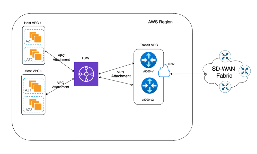
Configurations
Log into Catalyst SD-WAN Manager GUI and verify that all the controllers are up.
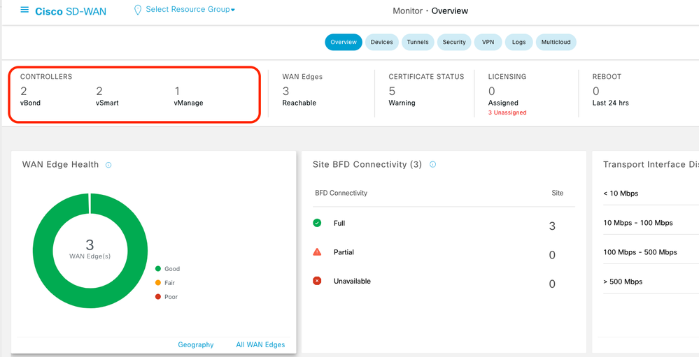
Step 1. Attach the AWS Device Template to Two C8000v Devices
On the Cisco SD-WAN Manager menu, navigate to Configuration > Templates.
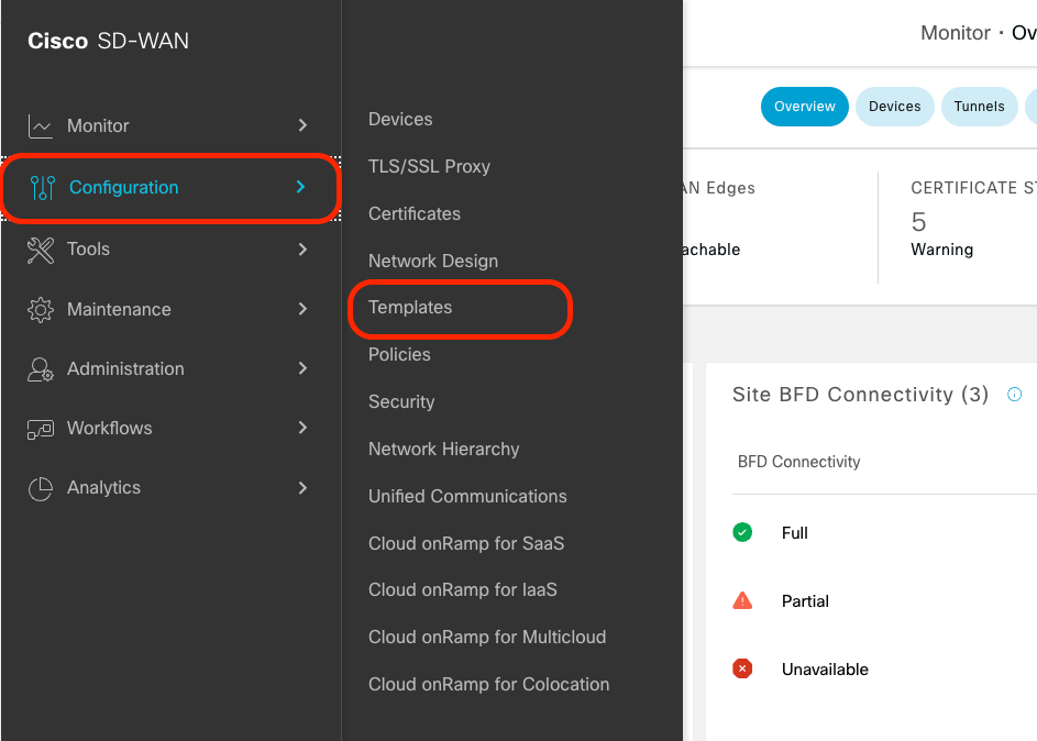
Click Device Templates > From Template. Type drop-down menu and select Default.

In the search bar, type AWS and C8000v. Then, click the 3 dots (...) next to the Default_AWS_TGW_C8000V_Template_V01 template. On the drop-down menu select Attach Devices.

Select two of the C8000v devices. Click the right-pointing arrow and then click Attach.
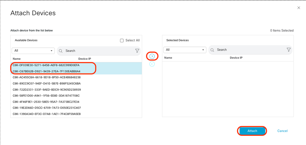
Click 3 dots (...) on the devices and navigate to Edit Device Template.

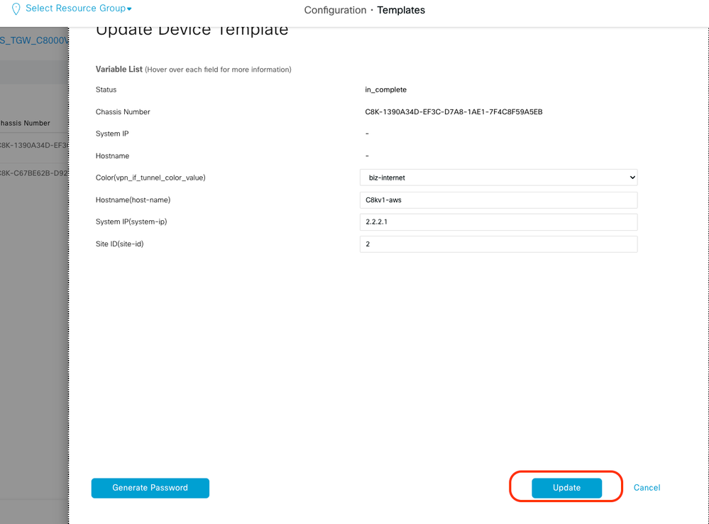
Click the drop-down menu and select Color, enter Hostname, System IP, Site ID. After entering these details, click Update.
Enter the values for each individual device, then click Update.
Example:
On Device 1
Color: Select biz-internet from Dropdown
Hostname: C8kv1-aws
System IP: 10.2.2.1
Site: ID 2
On Device 2
Color: biz-internet Color: biz-internet
Hostname: C8kv2-aws
System IP: 10.2.2.2
Site: ID 2
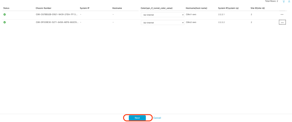
When you have finished with both devices, click Next.
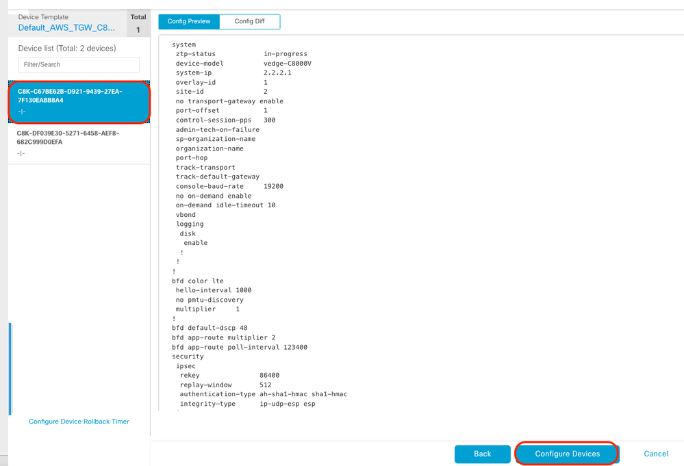
Click one of the devices, and make sure the config is correct. Click Configure Devices.
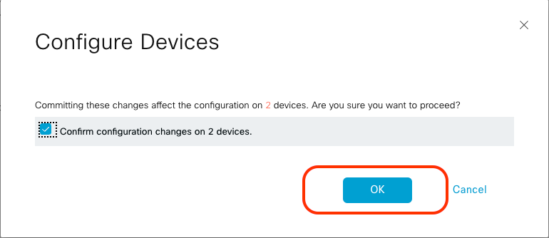
In the pop-up window, click the check box for Confirm configuration changes on 2 devices, and then click OK.
Confirm that the templates have been scheduled to be attached to the devices.

Step 2. Configure SD-WAN Integration to AWS
You can configure and manage Cloud onRamp for multicloud environments through the Cisco Catalyst SD-WAN Manager.
A configuration wizard in Cisco Catalyst SD-WAN Manager automates the bring-up of the transit gateway to your public cloud account and automates the connections between public-cloud applications and the users of those applications at branches in the overlay network. This feature works with AWS virtual private clouds (VPCs) on Cisco cloud routers.
A transit gateway is a network transit hub that you can use to interconnect your VPC and on-premises networks. You can attach a VPC, or a VPN connection to a transit gateway. It acts as a virtual router for traffic flowing between your VPC and VPN connections.
Cloud OnRamp for Multicloud supports integration with multiple AWS accounts.
Create AWS Cloud Account
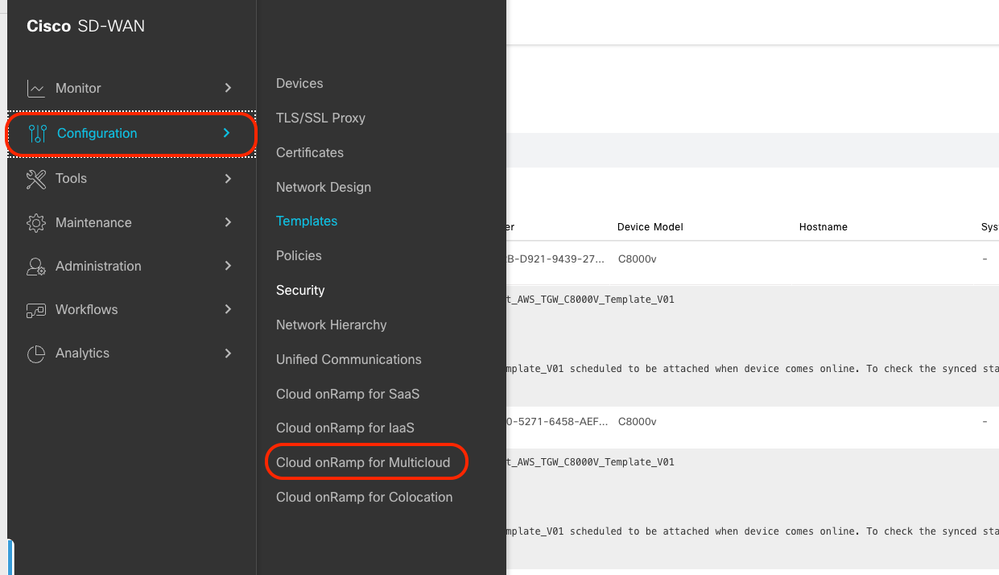
Navigate to Configuration > Cloud onRamp for Multicloud.
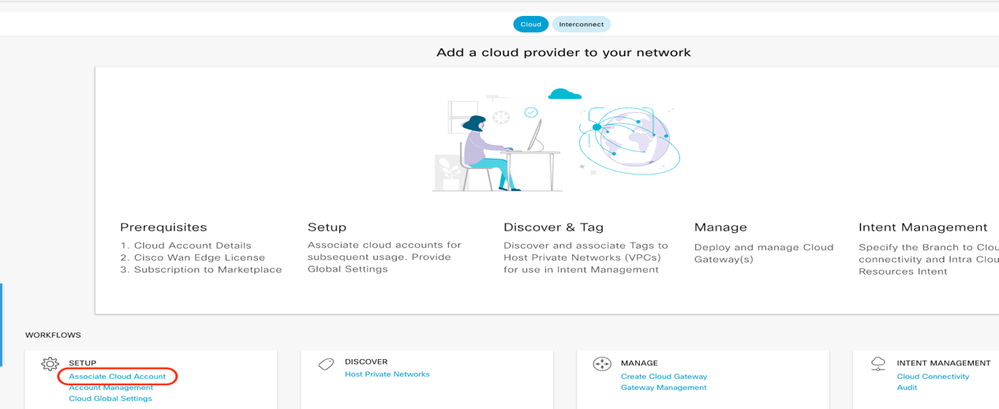
Click Associate Cloud Account in the Workflows > Setup.
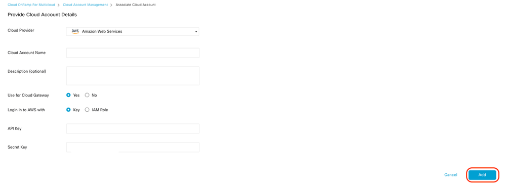
- In the Cloud Provider field, choose Amazon Web Services from the drop-down list.
- Enter the account name in the Cloud Account Name field.
- Choose Yes for creating Cloud Gateway.
- Choose the authentication model you want to use in the field Log in into AWS With.
If you choose the Key model, then provide API Key and Secret Key in the respective fields.
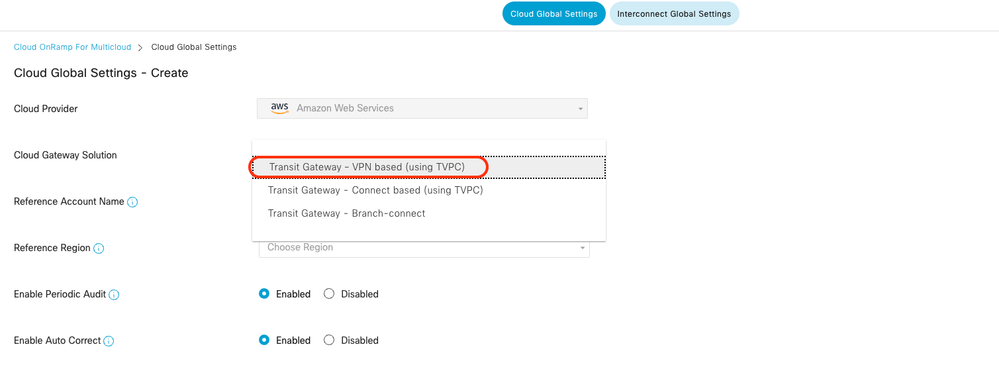
Configure Cloud Global Settings. Click Workflows > Setup > Cloud Global Settings.

Click Add, click the drop-down menu on Cloud Gateway Solution, and then select Transit Gateway – VPN Base (using TVPC).


Note: You cannot modify the pool when a few cloud gateways are already making use of pool. Overlapping of subnets is not allowed.
- Enter the Cloud Gateway BGP ASN Offset 68520.

Note: Acceptable start offset range is 64520 to 65500. It must be a multiple of 10.
- Click Site-to-Site Tunnel Encapsulation. Type drop-down menu, and then select IPSEC.
- The rest of radio buttons you keep as default which is enabled.

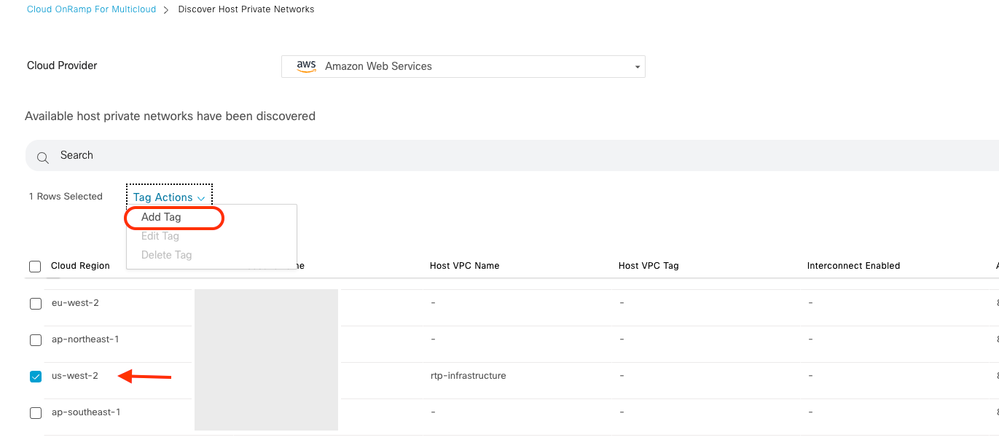
Next, you need to configure host VPCs by going back to the Cloud OnRamp For Multicloud main dashboard, under the Discover click Host Private Networks.

- Select the host VPC or VPCs that be attached to the Transit Gateway.
- Click theRegiondrop-down list to select the VPCs based on particular region.
- Click theTag Actionsto perform the actions:
Add Tag - group the selected VPCs and tag them together.
Edit Tag- migrate the selected VPCs from one tag to another.
Delete Tag- remove the tag for the selected VPCs.
A number of host VPCs can be grouped under a tag. All VPCs under the same tag are considered a singular unit. A tag ensures connectivity and is essential to view the VPCs inIntent Management.
Enter a Tag Name (the tag name can be anything), and then click Add.
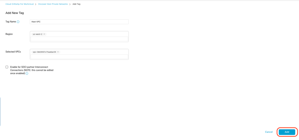
VPC tagging completed successfully.

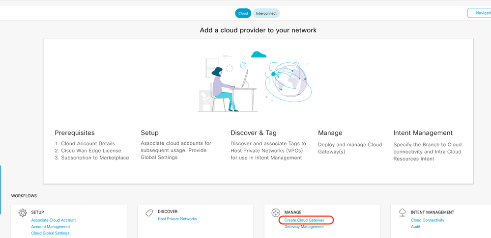
Return to Cloud onRamp for Multicloud and under the MANAGE, click Create Cloud Gateway.
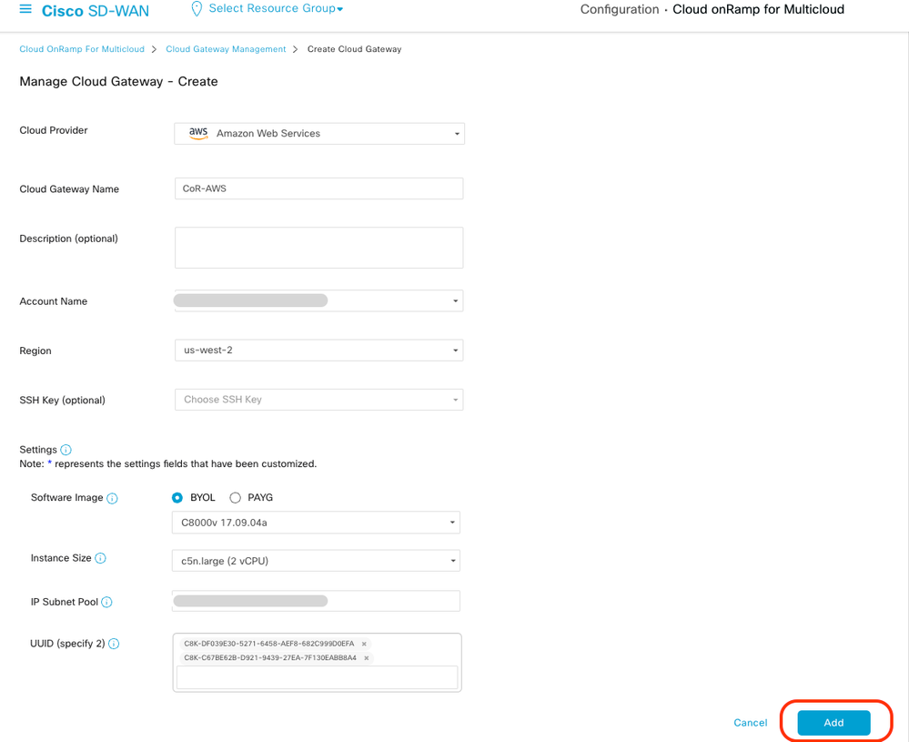
- Click the drop-down menu for Cloud Provider and select AWS.
- Enter a Cloud Gateway Name.
- Click the Account Name drop-down menu, it has the account information that was previously filled.
- Click the Region drop-down menu and select the region where the host VPCs were tagged.
- Software image, Instance Size, and IP Subnet pool are auto populated from the previously filled Global Cloud Gateway.
- Click the UUID drop-down. The two UUIDs for the C8000v that were previously attached in the device template are displayed. Select them, and then click Add.
Now Cloud Gateways start creating and then wait untill deployment of the of the Cloud Gateway is success.


Note: WAN Edges takes a few minutes before they are reachable after the process is completed.

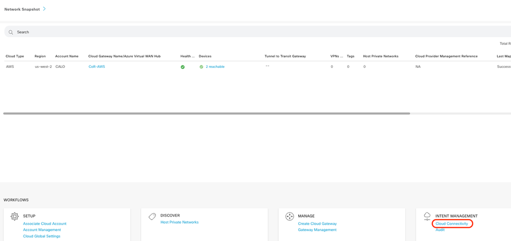
Two C8000v devices deployed in AWS are reachable. Now, click Cloud Connectivity.
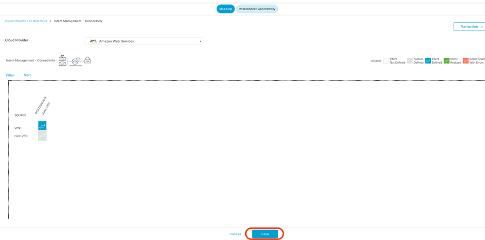
Click Edit to do VPN mapping and select VPN 1, then click Save.

Step 3. How to Remove Cloud Gateway
To delete the Cloud Gateway, under the Manage, select Gateway Management.

Then, click the 3 dots (...) on the desired cloud gateway and click Delete.

Verify
This section describes the outcomes for verification purposes.
After mapping, verify that the VPN 1 service VPN (VRF) is present on both two C8000v in AWS.
C8kv1-aws#show ip vrf
  Name                             Default RD            Interfaces
 1                                  1:1                   Tu100001
                                                           Tu100002
  65528                            <not set>               Lo65528
  65529                            <not set>               Lo65529
  Mgmt-intf                        1:512                      Gi1

C8kv2-aws#show ip vrf
  Name                             Default RD            Interfaces
  1                                  1:1                  Tu100001
                                                          Tu100002
  65528                            <not set>              Lo65528
  65529                            <not set>              Lo65529
  Mgmt-intf                        1:512                      Gi1
You can also see the OMP routes learned from the on-premises branch router, as well as the BGP routes from the host VPCs.
C8kv1-aws#show ip route vrf 1
Routing Table: 1

Codes: L - local, C - connected, S - static, R - RIP, M - mobile, B - BGP
       D - EIGRP, EX - EIGRP external, O - OSPF, IA - OSPF inter area
       N1 - OSPF NSSA external type 1, N2 - OSPF NSSA external type 2
       E1 - OSPF external type 1, E2 - OSPF external type 2, m - OMP
       n - NAT, Ni - NAT inside, No - NAT outside, Nd - NAT DIA
       i - IS-IS, su - IS-IS summary, L1 - IS-IS level-1, L2 - IS-IS level-2
       ia - IS-IS inter area, * - candidate default, U - per-user static route
       H - NHRP, G - NHRP registered, g - NHRP registration summary
       o - ODR, P - periodic downloaded static route, l - LISP
       a - application route
       + - replicated route, % - next hop override, p - overrides from PfR
       & - replicated local route overrides by connected

Gateway of last resort is not set

      10.0.0.0/8 is variably subnetted, 4 subnets, 2 masks
m        10.1.50.64/26 [251/0] via 10.1.1.231, 02:55:52, Sdwan-system-intf
B        10.2.0.0/16 [20/100] via 169.254.0.17, 02:55:22
                     [20/100] via 169.254.0.13, 02:55:22
m        10.2.112.192/26 [251/0] via 10.1.1.221, 02:55:52, Sdwan-system-intf
m        10.2.193.0/26 [251/0] via 10.1.1.101, 02:55:52, Sdwan-system-intf
      169.254.0.0/16 is variably subnetted, 4 subnets, 2 masks
C        169.254.0.12/30 is directly connected, Tunnel100001
L        169.254.0.14/32 is directly connected, Tunnel100001
C        169.254.0.16/30 is directly connected, Tunnel100002
L        169.254.0.18/32 is directly connected, Tunnel100002
B     172.31.0.0/16 [20/100] via 169.254.0.17, 02:55:22
                    [20/100] via 169.254.0.13, 02:55:22

C8kv2-aws#show ip route vrf 1
Routing Table: 1
Codes: L - local, C - connected, S - static, R - RIP, M - mobile, B - BGP
       D - EIGRP, EX - EIGRP external, O - OSPF, IA - OSPF inter area
       N1 - OSPF NSSA external type 1, N2 - OSPF NSSA external type 2
       E1 - OSPF external type 1, E2 - OSPF external type 2, m - OMP
       n - NAT, Ni - NAT inside, No - NAT outside, Nd - NAT DIA
       i - IS-IS, su - IS-IS summary, L1 - IS-IS level-1, L2 - IS-IS level-2
       ia - IS-IS inter area, * - candidate default, U - per-user static route
       H - NHRP, G - NHRP registered, g - NHRP registration summary
       o - ODR, P - periodic downloaded static route, l - LISP
       a - application route
       + - replicated route, % - next hop override, p - overrides from PfR
       & - replicated local route overrides by connected

Gateway of last resort is not set
      10.0.0.0/8 is variably subnetted, 4 subnets, 2 masks
m        10.1.50.64/26 [251/0] via 10.1.1.231, 02:57:17, Sdwan-system-intf
B        10.2.0.0/16 [20/100] via 169.254.0.9, 02:57:08
                    [20/100] via 169.254.0.5, 02:57:08
m        10.2.112.192/26 [251/0] via 10.1.1.221, 02:57:17, Sdwan-system-intf
m        10.2.193.0/26 [251/0] via 10.1.1.101, 02:57:17, Sdwan-system-intf
      169.254.0.0/16 is variably subnetted, 4 subnets, 2 masks
C        169.254.0.4/30 is directly connected, Tunnel100001
L        169.254.0.6/32 is directly connected, Tunnel100001
C        169.254.0.8/30 is directly connected, Tunnel100002
L        169.254.0.10/32 is directly connected, Tunnel100002
B     172.31.0.0/16 [20/100] via 169.254.0.9, 02:57:08
                    [20/100] via 169.254.0.5, 02:57:08
Related Information
SD-WAN Cloud OnRamp Configuration Guide
Technical Support & Documentation - Cisco Systems


 Feedback