Configure TCP Optimization Feature on Cisco IOS® XE SD-WAN cEdge Routers
Available Languages
Download Options
Bias-Free Language
The documentation set for this product strives to use bias-free language. For the purposes of this documentation set, bias-free is defined as language that does not imply discrimination based on age, disability, gender, racial identity, ethnic identity, sexual orientation, socioeconomic status, and intersectionality. Exceptions may be present in the documentation due to language that is hardcoded in the user interfaces of the product software, language used based on RFP documentation, or language that is used by a referenced third-party product. Learn more about how Cisco is using Inclusive Language.
Contents
Introduction
This document describes the Transmission Control Protocol (TCP) Optimization feature on Cisco IOS® XE SD-WAN routers, which was introduced in 16.12 release in August 2019. The topics covered are prerequisites, problem description, solution, the differences in TCP optimization algorithms between Viptela OS (vEdge) and XE SD-WAN (cEdge), configuration, verification and list of related documents.
Prerequisites
Requirements
There are no specific requirements for this document.
Components Used
The information in this document is based on Cisco IOS® XE SD-WAN.
The information in this document was created from the devices in a specific lab environment. All of the devices used in this document started with a cleared (default) configuration. If your network is live, ensure that you understand the potential impact of any command.
Problem
High latency on a WAN link between two SD-WAN sides causes bad application performance. You have critical TCP traffic, which must be optimized.

Solution
When you use TCP Optimization feature, you improve the average TCP throughput for critical TCP flows between two SD-WAN sites.
Take a look at the overview and differences between TCP Optimization on cEdge Bottleneck Bandwidth and Round-trip (BBR) and vEdge (CUBIC)
Fast BBR propagation time algorithm is used in the XE SD-WAN implementation (on cEdge).
Viptela OS (vEdge) has a different, older algorithm, called CUBIC.
CUBIC takes mainly packet loss into consideration and is widely implemented across different client operating systems. Windows, Linux, MacOS, Android already have CUBIC built-in. In some cases, where you have old clients running TCP stack without CUBIC, enabling TCP optimization on vEdge brings improvements. One of the examples, where vEdge TCP CUBIC optimization benefited, is on submarines that use old client hosts and WAN links experiencing significant delays/drops. Note that only vEdge 1000 and vEdge 2000 support TCP CUBIC.
BBR is mainly focused on round-trip time and latency. Not on packet loss. If you send packets from US West to East coast or even to Europe across the public internet, in the majority of the cases you don't see any packet loss. Public internet is sometimes too good in terms of packet loss. But, what you see is delay/latency. And this problem is addressed by BBR, which was developed by Google in 2016.
In a nutshell, BBR models the network and looks at each acknowledgment (ACK) and updates max Bandwidth (BW) and minimum Round Trip Time (RTT). Then control sending is based on model: probe for max BW and min RTT, pace near estimate BW and keep inflight near Bandwidth-Delay-Product (BDP). The main goal is to ensure high throughput with a small bottleneck queue.
This slide from Mark Claypool shows the area, where CUBIC operates:
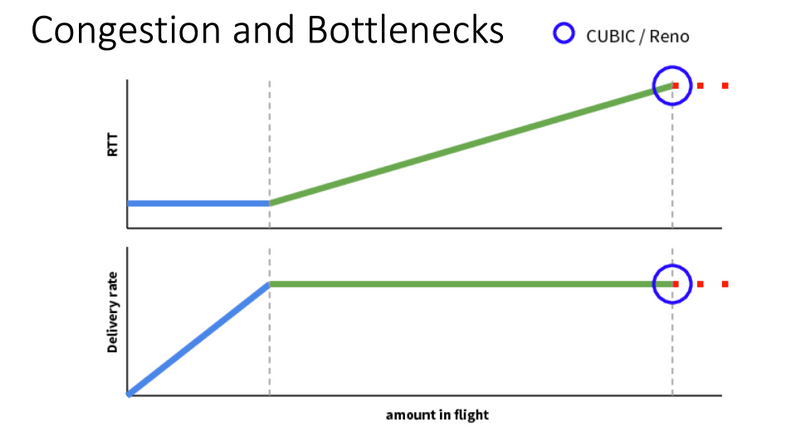
BBR operates in a better place, which is shown in this slide also from Mark Claypool: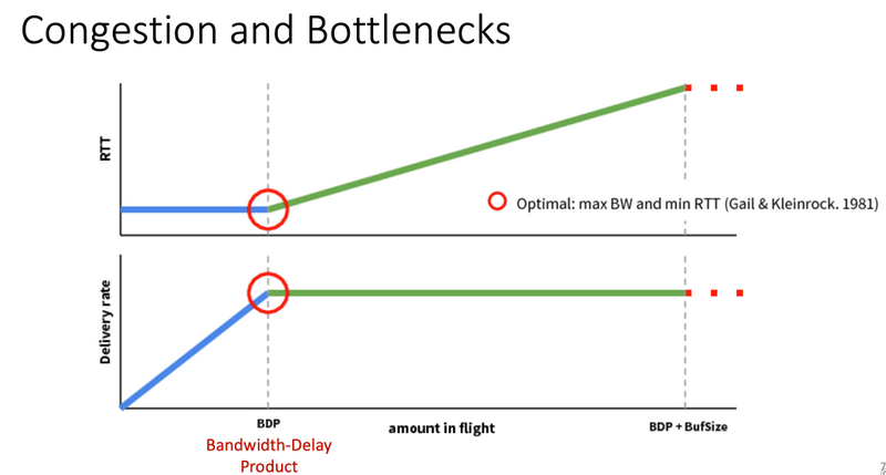
If you want to read more about the BBR algorithm, you can find several publications about BBR linked at the top of the bbr-dev mailing list home page Here.
In summary:
| Platform & Algorithm |
Key input parameter | Use Case |
| cEdge (XE SD-WAN): BBR | RTT/Latency | Critical TCP traffic between two SD-WAN sites |
| vEdge (Viptela OS): CUBICP | Packet Loss | Old clients without any TCP optimization |
Supported XE SD-WAN Platforms
In the XE SD-WAN SW Release 16.12.1d, these cEdge platforms support TCP Opmitization BBR:
- ISR4331
- ISR4351
- CSR1000v with 8 vCPU and min. 8 GB RAM
Caveats
- All platforms with DRAM less than 8 GB RAM are currently not supported.
- All platforms with 4 or less data cores are currently not supported.
- TCP Optimization does not support MTU 2000.
- Currently - no support for IPv6 traffic.
- Optimization for DIA traffic to a 3rd party BBR server not supported. You need to have a cEdge SD-WAN routers on both sides.
- In the data center scenario currently, only one Service Node (SN) is supported per one Control Node (CN).
- Currently a combined use case with security (UTD container) and TCP Optimization on the same device is not supported.
Note: ASR1k does not currently support TCP Optimization. However, there is a solution for ASR1k, where the ASR1k send TCP traffic via AppNav tunnel (GRE encapsulated) to an external CSR1kv for optimization. Currently (Feb. 2020) only one CSR1k as external service node is supported. This is described later in the configuration section.
This table summarizes caveats per release and underlines supported hardware platforms:
|
Scenarios |
Use Cases |
16.12.1 |
17.2.1 |
17.3.1 |
17.4.1 |
Comments |
|
Branch-to-Internet |
DIA |
No |
Yes |
Yes |
Yes |
In 16.12.1 AppQoE FIA is not enabled on internet interface |
|
SAAS |
No |
Yes |
Yes |
Yes |
In 16.12.1 AppQoE FIA is not enabled on internet interface |
|
|
Branch-to-DC |
Single Edge Router |
No |
No |
EFT |
Yes |
Need to support multiple SN |
|
Multiple Edge Routers |
No |
No |
EFT |
Yes |
Needs flow symmetry or Appnav flow sync. 16.12.1 not tested with |
|
|
Multiple SNs |
No |
No |
EFT |
Yes |
vManage enhancement to accept multiple SN IPs |
|
|
Branch-to-Branch |
Full Mesh Network (Spoke-to-Spoke) |
Yes |
Yes |
Yes |
Yes |
|
|
Hub-and-Spoke (Spoke-Hub-Spoke) |
No |
Yes |
Yes |
Yes |
||
|
BBR Support |
TCP Opt with BBR |
Partial |
Partial |
Full |
Full |
|
|
Platforms |
Platforms supported |
Only 4300 & CSR |
All but ISR1100 |
All |
All |
Configure
A concept of SN and CN is used for TCP Optimization:
- SN is a daemon, which is responsible for the actual optimization of TCP flows.
- CN is known as AppNav Controller and is responsible for traffic selection and transport to/from SN.
SN and CN can run on the same router or separated as different nodes.
There are two main use cases:
- Branch use case with SN and CN running on the same ISR4k router.
- Data Center use case, where CN runs on ASR1k and SN runs on a separate CSR1000v virtual router.
Both use cases are described in this section.
Use Case 1. Configure TCP Optimization on a Branch (all in one cEdge)
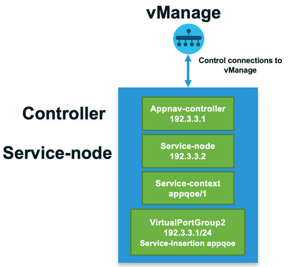
This image shows the overall internal architecture for a single standalone option at a branch:
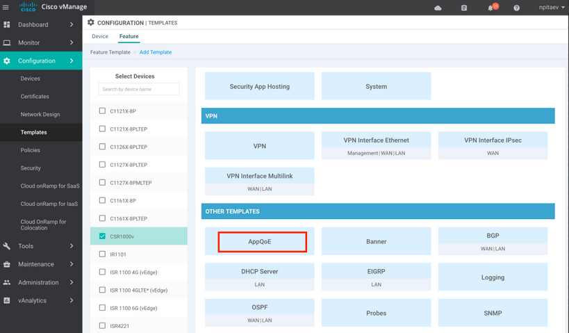
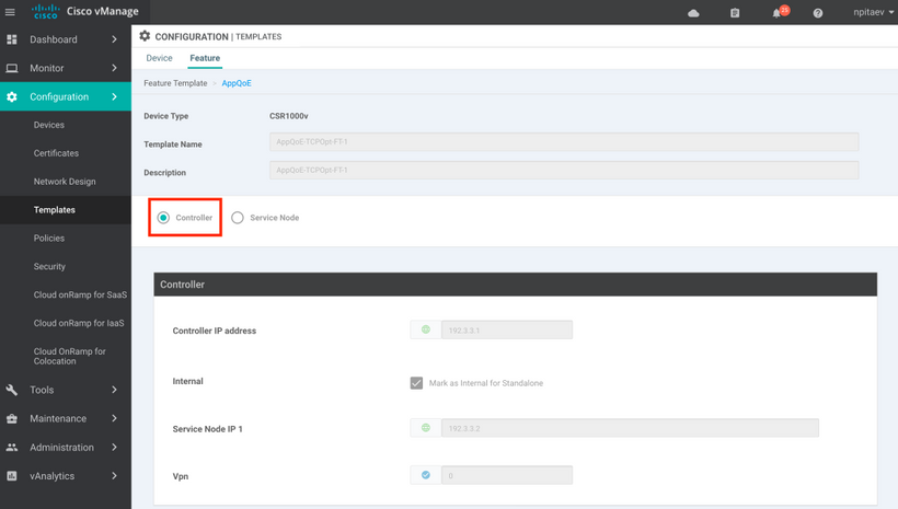
Step1. In order to configure TCP optimization, you need to create a feature template for TCP Optimization in vManage. Navigate to Configuration > Templates > Feature Templates > Other Templates > AppQoE as shown in the image.
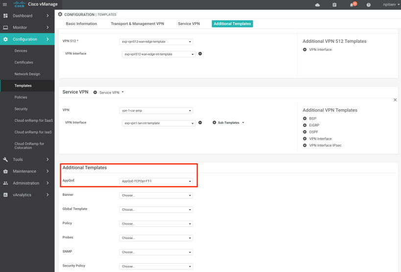
Step 2. Add the AppQoE feature template to the appropriate device template under Additional Templates:
Here is the CLI preview of the Template Configuration:
service-insertion service-node-group appqoe SNG-APPQOE
 service-node 192.3.3.2
!
service-insertion appnav-controller-group appqoe ACG-APPQOE
 appnav-controller 192.3.3.1
!
service-insertion service-context appqoe/1
 appnav-controller-group ACG-APPQOE
 service-node-group SNG-APPQOE
 vrf global
 enable
!
!
interface VirtualPortGroup2
 ip address 192.3.3.1 255.255.255.0
 no mop enabled
 no mop sysid
 service-insertion appqoe
!
Step 3. Create a centralized data policy with the definition of the interesting TCP traffic for optimization.
As an example; this data policy matches IP prefix 10.0.0.0/8, which includes source and destination addresses, and enables TCP optimization for it:


Here is the CLI preview of the vSmart Policy:
policy
 data-policy _vpn-list-vpn1_TCPOpt_1758410684
  vpn-list vpn-list-vpn1
    sequence 1
     match
      destination-ip 10.0.0.0/8
     !
     action accept
      tcp-optimization
     !
    !
  default-action accept
 !
 lists
  site-list TCPOpt-sites
   site-id 211
   site-id 212
  !
  vpn-list vpn-list-vpn1
   vpn 1
  !
 !
!
apply-policy
 site-list TCPOpt-sites
  data-policy _vpn-list-vpn1_TCPOpt_1758410684 all
 !
!
Use Case 2. Configure TCP Optimization in Data Center with an External SN
The main difference to the branch use case is the physical separation of SN and CN. In the all-in-one branch use case, the connectivity is done within the same router using Virtual Port Group Interface. In the data center use case, there is a AppNav GRE-encapsulated tunnel between ASR1k acting as CN and external CSR1k running as SN. There is no need for a dedicated link or cross-connect between CN and external SN, simple IP reachability is enough.
There is one AppNav (GRE) tunnel per SN. For future use, where multiple SNs are supported, it is recommended to use /28 subnet for the network between CN and SN.
Two NICs are recommended on a CSR1k acting as SN. 2nd NIC for SD-WAN controller is needed if SN has to be configured / managed by vManage. If SN is going to be manually configured/managed, then 2nd NIC is optional.
This image shows Data Center ASR1k running as CN and CSR1kv as Service Node SN :
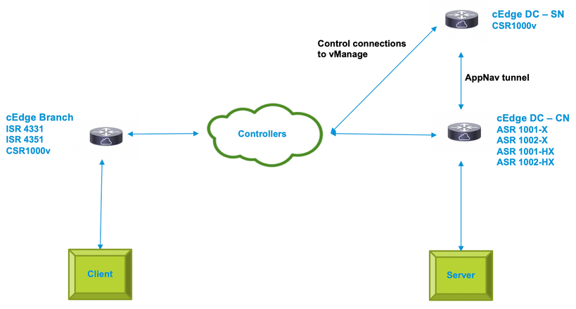
The topology for the data center use case with ASR1k and external CSR1k is shown here:
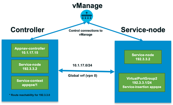
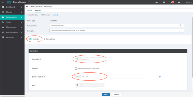
This AppQoE feature template shows ASR1k configured as Controller:
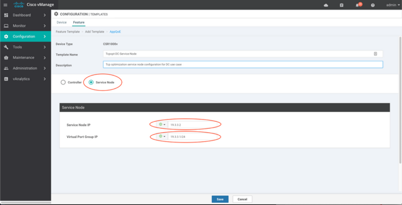
CSR1k configured as external Service Node is shown here:
Failover Case
Failover in the data center use case with CSR1k acting as SN, in case of external CSR1k failure:
- TCP sessions that already exist are lost because the TCP session on SN is terminated.
- New TCP sessions are sent to the final destination, but TCP traffic is not optimized (bypass).
- No blackholing for interesting traffic in case of SN failure.
Failover detection is based on AppNav heartbeat, which is 1 beat per second. After 3 or 4 errors, the tunnel is declared as down.
Failover in the branch use case is similar - in case of SN failure, the traffic is sent non-optimized directly to the destination.
Verify
Use this section in order to confirm that your configuration works properly.
Verify TCP Optimization on CLI with the use of this CLI command and see the summary of the optimized flows:
BR11-CSR1k#show plat hardware qfp active feature sdwan datapath appqoe summary
TCPOPT summary
----------------
  optimized flows    : 2
  expired flows      : 6033
  matched flows      : 0
  divert pkts        : 0
  bypass pkts        : 0
  drop pkts          : 0
  inject pkts        : 20959382
  error pkts         : 88

BR11-CSR1k#
This output gives detailed information about optimized flows:
BR11-CSR1k#show platform hardware qfp active flow fos-to-print all
++++++++++++++++++++++++++++++++++++++++++++++++++++++++++++++++++
     GLOBAL CFT  ~  Max Flows:2000000   Buckets Num:4000000
++++++++++++++++++++++++++++++++++++++++++++++++++++++++++++++++++
Filtering parameters:
    IP1 : ANY
    Port1 : ANY
    IP2 : ANY
    Port2 : ANY
    Vrf id : ANY
    Application: ANY
    TC id: ANY
    DST    Interface id: ANY
    L3 protocol : IPV4/IPV6
    L4 protocol : TCP/UDP/ICMP/ICMPV6
    Flow type : ANY
Output parameters:
    Print CFT internal data ? No
    Only print summary ? No
    Asymmetric : ANY
++++++++++++++++++++++++++++++++++++++++++++++++++++++++++++++++++
keyID: SrcIP SrcPort DstIP DstPort L3-Protocol L4-Protocol vrfID
==================================================================
   key #0: 192.168.25.254 26113 192.168.25.11 22 IPv4 TCP 3
   key #1: 192.168.25.11 22 192.168.25.254 26113 IPv4 TCP 3
==================================================================
   key #0: 192.168.25.254 26173 192.168.25.11 22 IPv4 TCP 3
   key #1: 192.168.25.11 22 192.168.25.254 26173 IPv4 TCP 3
==================================================================
   key #0: 10.212.1.10 52255 10.211.1.10 8089 IPv4 TCP 2
   key #1: 10.211.1.10 8089 10.212.1.10 52255 IPv4 TCP 2

Data for FO with id: 2
-------------------------
appqoe: flow action DIVERT, svc_idx 0, divert pkt_cnt 1, bypass pkt_cnt 0, drop pkt_cnt 0, inject pkt_cnt 1, error pkt_cnt 0, ingress_intf Tunnel2, egress_intf GigabitEthernet3
==================================================================
   key #0: 10.212.1.10 52254 10.211.1.10 8089 IPv4 TCP 2
   key #1: 10.211.1.10 8089 10.212.1.10 52254 IPv4 TCP 2

Data for FO with id: 2
-------------------------
appqoe: flow action DIVERT, svc_idx 0, divert pkt_cnt 158, bypass pkt_cnt 0, drop pkt_cnt 0, inject pkt_cnt 243, error pkt_cnt 0, ingress_intf Tunnel2, egress_intf GigabitEthernet3
==================================================================
++++++++++++++++++++++++++++++++++++++++++++++++++++++++++++++++++
           Number of flows that passed filter: 4
++++++++++++++++++++++++++++++++++++++++++++++++++++++++++++++++++
                       FLOWS DUMP DONE.
++++++++++++++++++++++++++++++++++++++++++++++++++++++++++++++++++

BR11-CSR1k#
Troubleshoot
There is currently no specific troubleshooting information available for this configuration.
Related Information
Revision History
| Revision | Publish Date | Comments |
|---|---|---|
1.0 |
29-Jan-2020 |
Initial Release |
Contributed by Cisco Engineers
- Nikolai PitaevCisco Engineering
Contact Cisco
- Open a Support Case

- (Requires a Cisco Service Contract)
 Feedback