Configure Overlay Transport Virtualization with ASR 1000
Available Languages
Download Options
Bias-Free Language
The documentation set for this product strives to use bias-free language. For the purposes of this documentation set, bias-free is defined as language that does not imply discrimination based on age, disability, gender, racial identity, ethnic identity, sexual orientation, socioeconomic status, and intersectionality. Exceptions may be present in the documentation due to language that is hardcoded in the user interfaces of the product software, language used based on RFP documentation, or language that is used by a referenced third-party product. Learn more about how Cisco is using Inclusive Language.
Contents
Introduction
This document describes the Overlay Transport Virtualization (OTV) network topologies supported on ASR1000 and Catalyst 8300/8500-series routers.
Prerequisites
Requirements
There are no specific requirements for this document.
Components Used
The information in this document is based on these software and hardware versions:
- ASR1000, IOS® XE version 16.10.1a and beyond
- Catalyst 8300, IOS® XE version 17.5.1a and beyond
- Catalyst 8500, IOS® XE version 17.6.1a and beyond
The information in this document was created from the devices in a specific lab environment. All of the devices used in this document started with a cleared (default) configuration. If your network is live, ensure that you understand the potential impact of any command.
Background Information
ASR1000 supports OTV since Cisco IOS® XE Release 3.5. The Catalyst 8300 series router begins support with IOS® XE17.5.1a and the Catalyst 8500 series routes begins support with IOS® XE version 17.6.1a.
OTV provides Layer 2 connectivity between remote network sites by MAC address-based routing and IP-encapsulated forwarding (MAC-in-IP) across a transport network to provide support for applications that require Layer 2 adjacency, such as clusters and virtualization. OTV uses an overlay control-plane protocol to learn and propagate MAC routing information across the overlay network. The OTV control-plane protocol uses Intermediate-System-to-Intermediate-System (IS-IS) messages to build adjacencies to remote sites and to send MAC route updates to remote sites. OTV builds Layer 2 adjacencies to remote sites on the overlay network by auto discover of remote OTV devices.
The benefits of OTV for Layer 2 extension include:
- No MPLS requirement
- No complex Ethernet over Multiprotocol Label Switching (EoMPLS) configuration for mesh
- No complex Virtual Private LAN Services (VPLS) deployment for layer 2 extensions
- Native spanning-tree isolation
- no need to explicitly configure bridge data protocol unit (BPDU) filters
- default isolation of spanning-tree problems to a given data center
- Native unknown unicast flooding isolation
- unknown unicast MAC packets are not forwarded
- support for per-MAC unknown unicast forward is allowed
- Address Resolution Protocol (ARP) optimization with the OTV ARP caching
- reduces unnecessary WAN traffic
- Simplified provisioning of First Hop Redundancy Protocol (FHRP) isolation
- Simplified addition of sites
- Simplified redundancy configuration
- Ability to have a “drop in appliance” for migrations when temporary services are required
Requirements
The subsequent items are the primary rules to keep in mind when an OTV deployment is designed. If these rules are adhered to, design and deployment are streamlined.
- One and only one interface can be used to transmit the OTV encapsulated traffic, known as the join interface, for all configured OTV Overlay interfaces
- One and only one interface can be used to configure the data center L2 service instances for the OTV site VLAN and the VLANs extended between data centers for all configured OTV Overlay interfaces
- Port-channels can be used for interface redundancy and connection to VSS or VPC switches and are supported as the “one and only one” interface for connectivity.
- All OTV routers must be contactable via the join interface
- Spanning tree must be configured on the OTV router that points to the data center
- IGMP snooping and querying must be configured to correctly forward data center multicast traffic
- A given data center can be configured with 1 or 2 OTV routers. With two routers they distribute VLAN forwarding in an odd/even fashion based on VLAN number. Each OTV router in a data center act as backup for the other.
- Multihomed pairs must be configured with the same OTV site identifier
- ASR1000/Catalyst 8300/Catalyst 8500 and Nexus 7000 can participate in the same OTV network
- Nexus 7000 does not support OTV fragmentation or encryption, so these features can not be used in a “hybrid” deployment.
There are certain designs for back-to-back connectivity that are supported which do not adhere to the rules stated. While these configurations are supported, they are not recommended. Details on those can be found in the later section “Special case unicast topology”.
It can not be emphasized enough that current OTV software has the “one and only one” interface restriction when configuration of the join and L2 access interfaces for OTV. A Port-channel interface can be used for redundancy. Connection of the Port-channel to Nexus 7000s in a VPC is supported. A basic port-channel connection to a single switch is also supported.
OTV Implementation Types
OTV requires a single join interface and a single L2 interface. One and only one of each of these can be supported per OTV router. OTV also requires that a site VLAN be configured so that multihomed OTV routers can communicate with each other through the local network. Even single-homed OTV routers must have the OTV site VLAN configured. Additionally, each site or data center must have a unique site-identifier configured. Dual-homed OTV routers must use the same site-identifier and be able to communicate over the same VLAN.
The subsequent configuration gives the basic fundamental configuration necessary for OTV. However, it is not complete as the unicast or multicast core configuration must be added. Those are detailed in subsequent sections of this document.
otv site bridge-domain 100
otv site-identifier 0000.0000.1111
!
interface Overlay1
  no ip address
  otv join-interface GigabitEthernet0/0/0
  service instance 99 ethernet
    encapsulation dot1q 99
    bridge-domain 99
  !
  service instance 90 ethernet
    encapsulation dot1q 90
    bridge-domain 90
!
interface GigabitEthernet1/0/1
  no ip address
  negotiation auto
  service instance 100 ethernet
    encapsulation dot1q 100
    bridge-domain 100
  !
  service instance 99 ethernet
    encapsulation dot1q 99
    bridge-domain 99
  !
  service instance 98 ethernet
    encapsulation dot1q 98 second-dot1q 1098
    rewrite ingress tag trans 2-to-1 dot1q 90 symmetric
    bridge-domain 90
The service instance configuration is used for all L2 interface configuration with OTV.
Each service instance on the L2 interface must be associated with a specific single or double tagged encapsulation.
In turn, each of those service instances must be associated with a bridge-domain.
That bridge-domain is used on a service instance configured on the Overlay interface.
The bridge-domain is the the glue that links the Overlay service instance to the L2 interface service instance.
The encapsulation of traffic on the overlay interface must match the encapsulation of the traffic after rewrite ingress on the L2 interface.
In the example, traffic that ingresses on Gig1/0/1 service instance 99 has a single 802.1Q VLAN of 99 and bridge domain 99. The corresponding service instance with bridge-domain 99 on the Overlay interface also is configured for a single 802.1Q VLAN of 99. This case is the most straightforward.
In the example, traffic that ingresses on Gig1/0/1 service instance 98 has a double 802.1Q VLAN of 99 and 1098 and bridge domain 90. The corresponding service instance with bridge-domain 90 on the Overlay interface is configured for a single 802.1Q VLAN of 90. Clearly these are not the same. The rewrite ingress command ensures that the tags are properly translated as traffic moves through the ingress interface. Traffic that ingresses the L2 interface has the 98/1098 802.1Q VLANs replace with a single VLAN of 90. The symmetric keyword ensures that traffic that egresses out the L2 interface has the single 802.1Q VLAN of 90 replace with 98/1098.
Any service instances with multiple 802.1Q VLANs that are extended by OTV must use the rewrite ingress command. OTV encapsulation only supports a single VLAN identifier. For that reason, any double VLAN configuration on the L2 interfaces must be rewritten to a single tag on the Overlay interface service instance. This precludes support for ambiguous VLAN configurations.
For more details regarding tag rewrite, see this document: https://www.cisco.com/c/en/us/td/docs/ios-xml/ios/cether/command/ce-cr-book/ce-m1.html
In this example, the OTV site bridge-domain is 100.
- The OTV site bridge-domain is configured only on the L2 interface.
- The OTV site bridge-domain must never be configured on the Overlay interface as this makes the OTV deployment unstable.
- The OTV site VLAN must be connected only to the OTV routers and not carry any other data center / user traffic.
- The OTV site VLAN must be on the same physical interface as the OTV extended VLANs.
Multihome
A data center can be connected with a single OTV host or up to 2 for redundancy, also known as Multihome. Multihome is used for resiliency and load balancing. When more than one edge device is present at a site and both participate in the same overlay network, the site is considered multihomed. OTV Multihome splits the VLANs among the two OTV routers that belong to the same site in an odd/even fashion based on the VLAN number. One edge device is elected as the AED for all odd VLANs, while the other OTV router is elected as the AED for all even VLANs. Each AED is also a standby for the VLANs that are active on the other router. In case of link or node failure in one of the AEDs, the standby AED becomes active for all VLANs.
If two ASR1000s are connected in the same data center to do Multihome, there is no need for a dedicated link between the two ASR1000s. OTV uses the OTV site VLAN that is propagated through the internal interface and communication through the join interface to determine which routers are responsible for even and odd VLANs.
ASR1000s and Nexus 7000s cannot be mixed in the same data center with OTV configured on both routers as backup for the other. Multihome in a given data center is supported for matched platforms (ASR1000 or Nexus 7000). You can have ASR1000s in one data center and Nexus 7000s in another data center. Interoperability between these two platforms has been tested and supported. Some data centers can be multihomed while others are single homed.
Multihomed ASR1000 routers pairs must run the same version of Cisco IOS® XE software.
If Multihome is used, it is highly recommended spanning-tree must be enabled on the OTV routers as this enables the OTV router to send out a topology change notification (TCN) which causes the adjacent L2 switch device (along with other switches in the spanning-tree) to reduce their age timer from the default to 15 seconds. This greatly increases speed convergence when there is a failure or recovery between the multihomed pair. Spanning-tree can be enabled for all configured service-instances (connected to OTV or otherwise) by the addition of the subsequant line to global configuration.
spanning-tree mode [ pvst | rapid-pvst | mst ]No specific per vlan or per service instance configuration is required.
Multicast Core
Multicast network requires full mesh connectivity across the WAN. All OTV routers need to be connected together through the join interface.
Figure 1. Supported multicast network topology
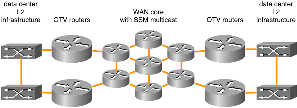
This figure shows an example of two data centers that are connected through a core in full mesh. Source specific multicast (SSM) Protocol Independent Multicast (PIM) is run between the OTV routers and WAN core routers. Any number of core routers is supported as long as there is full mesh connectivity. There is no explicit maximum latency requirement for OTV connectivity across the WAN core.
Figure 2. Unsupported multicast network topology
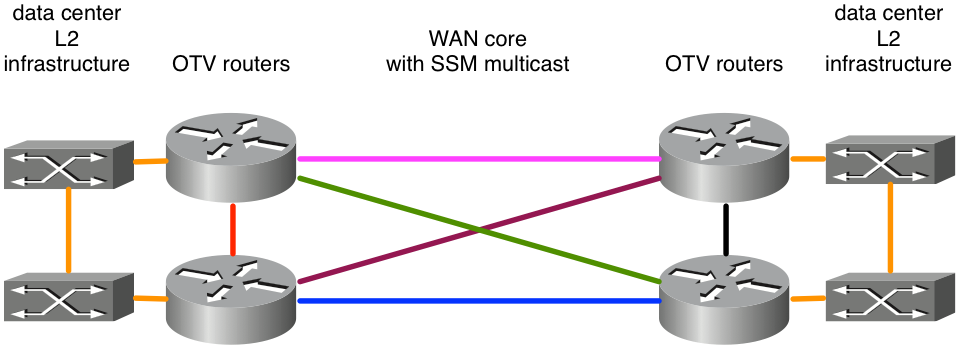
Because ASR1000/OTV expects to receive multicast messages on a single join interface from all its peers, per the example, this would result in unstable OTV deployment. Suppose the east-west links in pink and blue were configured as join interfaces. When the pink link failed, the router would no longer be able to receive OTV updates on that interface. An alternate path via the green or purple links would be unacceptable because the join-interface is explicitly configured. Updates must be received on that interface. It is not supported at this time to use a Loopback interfaces as the join interface.
If users do not own their backbone, then they must make sure that their service provider supports multicast in their core, and the service provider can respond to Internet Group Management Protocol (IGMP) query messages. OTV on ASR1000 acts as multicast host (forwards IGMP join messages), not as a multicast router to the core WAN multicast topology.
The transport network between the OTV routers must support the PIM sparse mode (Any Source Multicast [ASM]) for the provider multicast group and SSM for the delivery group.
Multicast cores require some specific configuration on the Overlay interface for a control group as well as a range of data multicast groups that are used for forwarding data.
ip multicast-routing distributed
ip pim ssm default
!
interface Port-channel60
 encapsulation dot1Q 30
 ip address 10.0.0.1 255.255.255.0
 ip pim passive
 ip igmp version 3
!
interface Overlay99
 no ip address
 otv control-group 239.1.1.1
 otv data-group 232.192.1.0/24
 otv join-interface Port-ch60
Multicast OTV deployments require that the join interface be configured as a PIM passive interface. IGMP can be configured for different versions as needed. The overlay interface must have a control-group and data-group configured. The control group is a single multicast group used for OTV management. The data-group is a range of multicast addresses used to transport user data between data centers. If the data-group is not in the 232.0.0.0/8 IP space the additional command “ip pim ssm range” must configured to include the range required by OTV.
The transport network between the OTV routers must support the PIM sparse mode (Any Source Multicast [ASM]) for the provider multicast group and Source Specific Multicast (SSM) for the delivery group.
Unicast Core with Adjacency Servers
Cisco IOS® XE 3.9 added support for OTV with a unicast core. Both unicast and multicast cores for OTV continue to be supported for all ASR1000 platforms and future releases from Cisco IOS® XE 3.9.
Figure 3. Unicast network topology
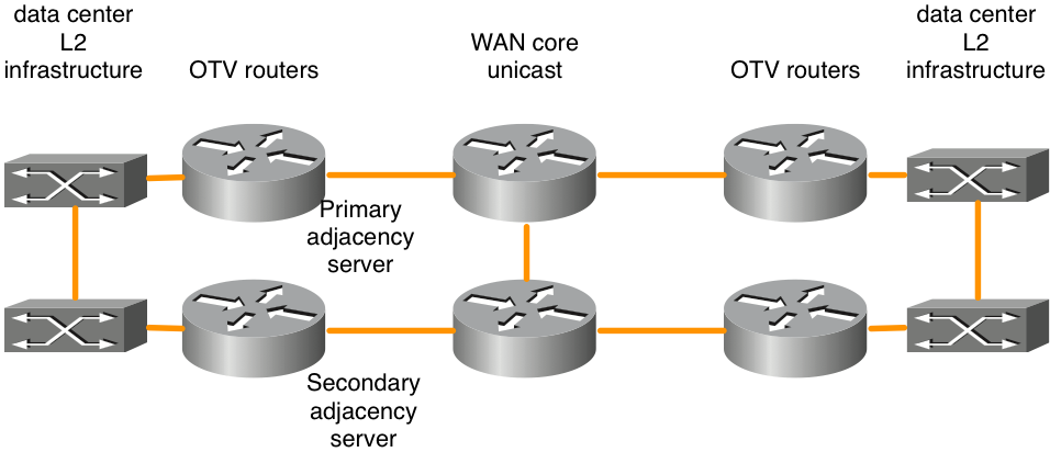
The OTV Adjacency Server feature enables unicast-only transport between OTV edge. OTV routers configured with the adjacency server role keep a list of all the known OTV routers. They provide that list to all registered OTV routers so that they have a list of devices that must receive replicated broadcast and multicast traffic.
The OTV control plane over a unicast-only transport works exactly the same way as OTV with multicast core, except that in a unicast-core network, each OTV edge device needs to create multiple copies of each control plane packet and unicast them to each remote edge device in the same logical overlay.
In the same line of thinking, any multicast traffic from the data center is replicated on the local OTV router and multiple copies are sent to each of the remote data centers. While this is less efficient than to be contingent on the WAN core to do the replication, the configuration and management of the core multicast network is not required. If there is only a small amount of data center multicast traffic or there are only a small number of data center locations (four or less), a unicast core for OTV forwarding is usually the best choice. Overall, the operational simplification of the unicast-only model makes the unicast core deployment option prefered in scenarios where LAN extension connectivity is required only between four or less data centers. It is recommended to have at least two adjacency servers configured, one primary and one backup. There is not an option for active/active adjacency server configuration.
OTV routers must be configured accordingly to properly identify and register with the appropriate adjacency server.
|
Primary adjacency server |
Secondary adjacency server |
Other OTV routers |
|
|
OTV join interface IP address |
10.0.0.1 |
10.2.2.24 |
other IP addresses |
|
Configuration |
interface Overlay 1 |
interface Overlay 1 |
interface Overlay 1 |
There are certain designs for back-to-back connectivity that are supported with unicast OTV forwarding which do not adhere to the “full mesh” rules. While these configurations are supported they are not recommended. This type of deployment is most common when data centers are connected via dark fiber. Details on this configuration option can be found in the later section “Special case unicast topology”.
OTV on a Stick Versus Inline
There are two models to deploy OTV in your data center: on a stick and inline. In the previously presented design scenarios, OTV routers were inline between the data center and the service provider core network. However, the addition of the OTV router as an appliance that it not in the transport path of all traffic could be more desirable. Sometimes the requirement is to not change the current topology to connect to the service provider through current equipment (for example, a brownfield deployment with Catalyst 6000 switch or Nexus switch hardware that does not support OTV). Thus, it is preferred to deploy OTV on ASR1000 as on a stick as an OTV appliance.
Figure 4. Inline versus on-a-stick topology
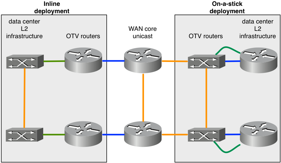
The diagram demonstrates the two deployments models that can be part of the same overlay. The green links connected to the OTV routers are configured as L2 access interfaces to accept VLAN traffic. The blue links connected to the OTV routers are the join interfaces that carry OTV encapsulated VLAN traffic.
It can be necessary to configure a feature that are not supported with OTV. For example, OTV and MPLS cannot be configured on the same box. As a result, it can be a good option to use ASR1000/OTV on a stick, and configure MPLS on the router that sits in front of OTV router.
Port-channels for Layer 2 and Layer 3
Cisco IOS® XE 3.10 code for ASR1000 added support layer 2 and layer 3 Port-channel configuration with OTV. Layer 2 Port-channel can be used as the internal interface. The Port-channel must consist of up to 4 physical interfaces. Layer 3 Port-channel can be used as the join interface.
Figure 5. Port channels used for L2 connectivity
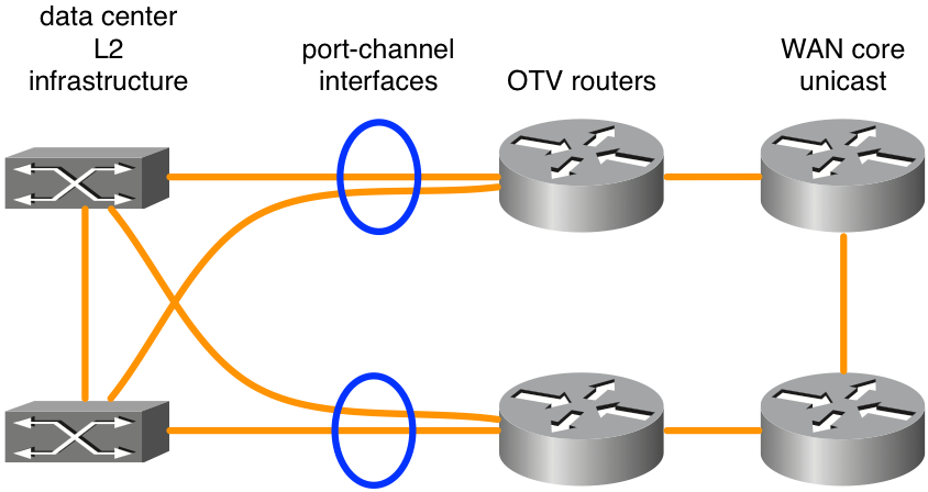
The diagram shows a typical Port-channel scenario with two switches in VSS (Catalyst 6000 series) or VPC (Nexus 7000 series). This type of design gives redundancy with dual OTV routers and dual connectivity to data center infrastructure. No special configuration for OTV other than basic Port-channel configuration is required if VSS or a VPC is used on L2 switching equipment adjacent to the OTV routers.
Default Gateway
By definition, OTV creates the same L3 subnet in multiple locations locations. This requires some special considerations when routing L3 traffic to and and from the extended VLANs. L3 routing can be configured on the OTV routers themselves or it can be configured on other devices connected to the extended VLANs. Additionally, in each scenario first hop redundancy protocols (FHRP) such as Hot Standby Redundancy Protocol (HSRP) or Virtual Router Redundancy Protocol (VRRP) can be deployed for redundancy. HSRP can run local to a given data center or extend between data centers (not typical).
The best practice for OTV deployments that utilize FHRP, is to have local instances of the FHRP ran in each data center. Those instances of FHRP utilize the same virtual MAC address and IP address so that when virtual machines (VMs) move between data centers they have an uninterrupted connection. If the MAC address of the default router were to change between data centers, the VM’s would not be able to communicate off subnet until the the VM’s default gateway ARP entry timed out.
To properly deploy a FHRP with OTV, it is necessary to consider what L2 and L3 traffic must be filtered and isolated from OTV. At the L2 level, this is necessary to keep OTV from catch sight of the same L2 virtual MAC used by the FHRP in multiple locations. Filters are required at the L3 level to keep HSRP and VRRP advertisements isolated to each data center so that the active/listening/standby election is localized to each data center.
By default, the FHRP filters are enabled when OTV is enabled. It can be disabled if the design requires that FHRP be extended between data centers. The L2 filtering of virtual MAC addresses is NOT enabled by default and must be manually configured.
figure 6. Example of recommended deployment for FHRP
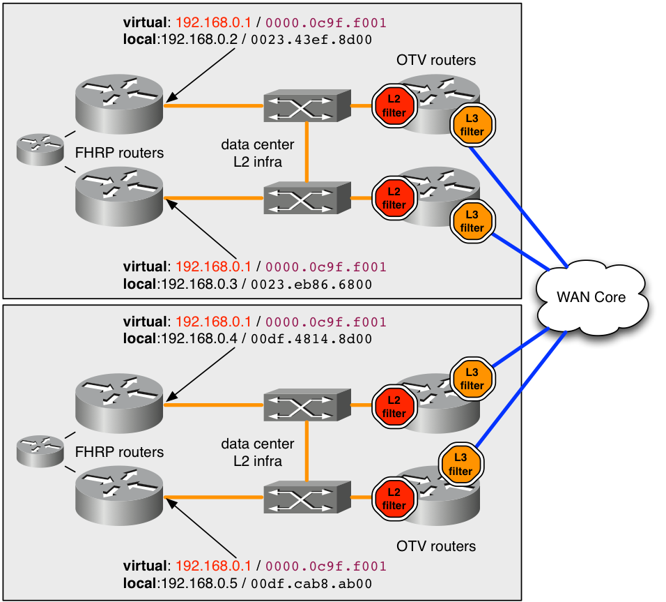
In the example, the virtual MAC address 0000.0c9f.f001 is used for the IP address 192.168.0.1 which hosts on the extended VLAN for connectivity off the subnet. Use of the same virtual MAC and IP in both data centers, a host has seamless connectivity off the subnet when it transfers between datacenters.
In order to keep the MAC address 0000.0c9f.f001 hidden from OTV in multiple locations, an ingress L2 filter (red stop in the diagram) must deployed for the VLAN on each of the OTV routers , that service the VLAN. By the ACL filter the filter ACL configured on the L2 service instances for ingress, any packets sourced from that MAC are dropped before the OTV process on the ASR1000 can see them. Thus, OTV never learns about the MAC, and does not advertise it to remote data centers.
The recommended configuration to catch all well known / default FHRP virtual MAC traffic is given here.
mac access-list extended otv_filter_fhrp
 deny 0000.0c07.ac00 0000.0000.00ff any
 deny 0000.0c9f.f000 0000.0000.0fff any
 deny 0007.b400.0000 0000.0000.00ff any
 deny 0000.5e00.0100 0000.0000.00ff any
 permit any any
This ACL matches the well known MAC address spaces associated with HSRP versions 1 and 2, Gateway Load Balancing Protocol (GLBP), and VRRP (in that order) . If the virtual MAC is configured to use a non-standard value not based on the FHRP group number, then it must be explicitly added to the ACL example. The ACL must be added to the L2 service instance (shown here).
interface Port-channel10
  description *** OTV internal interface ***
  no ip address
  no negotiation auto
!
  service instance 800 ethernet
    encapsulation dot1q 800
    mac access-group otv_filter_fhrp in
    bridge-domain 800
It is also necessary to manage communication between the FHRP hosts at the L3 level as well. There are four FHRP routers configured on a single extended subnet in the diagram. Without some degree of L3 Filters, all four routers would see each other and elect a single active device and have 3 in various standby states. Thus one data center would have two local standby FHRP routers but not have L2 connectivity to the remote active router due to the previously discussed L2 Filters.
The desired result is to have one active and one standby FHRP router in each data center. The previously discussed ingress L2 filter does not catch this election traffic since the election process uses the router’s actual IP and MAC addresses. By default, the subsequant ACL is applied as egress on the Overlay interface. Egress for the Overlay interface would be traffic towards the WAN core. The ACL does not show up in running configuration, however it can be observed with “show ip access-list”. It filters out the FHRP election traffic based on UDP port number.
Extended IP access list otv_fhrp_filter_acl
    10 deny udp any any eq 1985 3222
    20 deny 112 any any
    30 permit ip any
The only reason to disable this filter would be if you want all FHRP routers on a VLAN, to participate in the same election for active status. In order to disable this filter, configure “no otv filter-fhrp” on the Overlay interface.
Unknown Unicast Traffic
By default, unicast traffic received from the LAN by the OTV router that is destined for a MAC address that is not known to exist at a remote OTV location is dropped. This traffic is known as unknown unicast. This drop action goes towards the WAN core that limits the amount of bandwidth consumed on the WAN by broadcast traffic. The general expectation is that all hosts on the LAN issue enough broadcast traffic (ARPs, protocol broadcasts, and so on) that always is to be seen by an OTV router, advertised, and thus “known”.
Certain applications take advantage of silent hosts. On a normal switching infrastructure this is not a problem as L2 broadcasting of unknown unicast MAC addresses on the LAN allows the silent host to see the traffic. However, in an OTV environment, the OTV router blocks the traffic between the datacenters.
To compensate for this, a feature known as Selective Unicast Forwarding was integrated into Cisco IOS® XE. XE 3.10.6, XE3.13.3, XE 3.14.1, XE3.15 and all releases after have support for selective unicast forwarding.
It is configured by the addition of a single command per MAC address on the Overlay interface. For example:
interface Overlay1
  service instance 100 ethernet
    encapsulation dot1q 100
    otv mac flood 0000.0000.0001
    bridge-domain 100
Any traffic destined for 0000.0001.0001 must be flooded to all remote OTV routers with VLAN 100 in this example. This can be observed by the subsequant command:
OTV_router_1#show otv route
Codes: BD - Bridge-Domain, AD - Admin-Distance,SI - Service Instance, * - Backup Route
OTV Unicast MAC Routing Table for Overlay99
 Inst VLAN BD     MAC Address    AD    Owner  Next Hops(s)
----------------------------------------------------------
 0    100  100    0000.0000.0001 20    OTV    Flood
If that MAC address is learned at a remote site, an entry must be added to the forward table that takes precedence over the flood entry.
OTV_router_1#show otv route
Codes: BD - Bridge-Domain, AD - Admin-Distance,SI - Service Instance, * - Backup Route
OTV Unicast MAC Routing Table for Overlay99
 Inst VLAN BD     MAC Address    AD    Owner  Next Hops(s)
----------------------------------------------------------
 0    100  100    0000.0000.0001 20    OTV    Flood
 0    100  100    0000.0000.0001 50    ISIS   OTV_router_3
Generally, a flooding entry for a given MAC address must be configured on all OTV routers with that VLAN.
Remote Multicast Sources
ASR1000 thats an OTV router does not forward multicast IGMP join requests received from the LAN. The subsequent diagram details the topology where this can be an issue.
Figure 7. Remote multicast sources
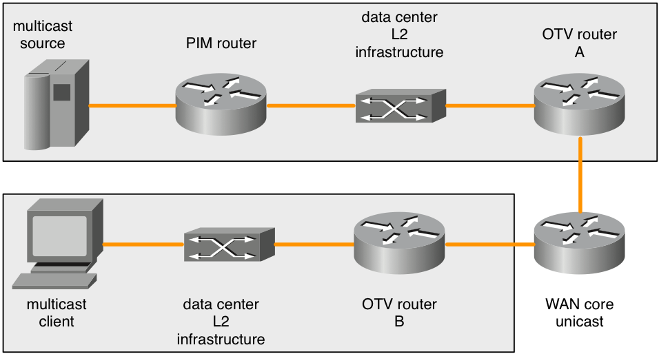
When a multicast IGMP join is sent by the multicast client, the ASR1000 (OTV router B) observes it and advertises interest in the multicast group. The remote OTV routers (OTV router A) must forward any traffic to that multicast group that they see on their local L2 broadcast domain. The remote ASR1000 (OTV router A) however does not regenerate the multicast IGMP join requests when interest in a multicast group is advertised to from the client’s OTV router (OTV router B).
When multicast sources are on the same L2 broadcast domain as the OTV router then this is not a problem. The OTV router must be configured as an IGMP querier. This shows up in any multicast traffic present on the L2 broadcast domain. However, only a PIM join request would cause a PIM router to forward a multicast source from a different L2 broadcast domain to the L2 broadcast domain the OTV router is on.
The remote IGMP join request is not forwarded or regenerated. OTV routers are not PIM routers either. So topologies with multicast sources not directly on the L2 broadcast domain with the OTV router have no way to infrom PIM routers to forward source traffic when there is interest by a remote client.
There are two workarounds to this problem.
First, a local IGMP client(s) can be deployed on the L2 broadcast domain attached to the OTV router (OTV router A). That IGMP client would have to subscribe to any multicast groups that remote clients could subscribe to. That would cause the PIM router to forward the multicast traffic to the broadcast domain adjacent to OTV router A. The IGMP queries would then draw in any multicast traffic and it would be sent across the overlay.
The other solution would be to configure a “ip igmp static-join” for any groups that remote clients could possibly subscribe to. This also would cause the PIM router to forward the multicast traffic to the broadcast domain adjacent to OTV router A.
This limitation is known and is part of the design specification. It is not considered to be a bug, but a limit in supported topology at this time.
QoS Considerations
By default on ASR1000, the TOS value in the added OTV header is copied from the L2 packet’s 802.1p bits. If the L2 packet is untagged then a value of zero is used.
Nexus 7000 has a different default behavior in 5.2.1 software and newer. If the desired behavior is to copy the inner packets TOS value into the outer, additional QoS configuration can achieve this. This gives the same behavior as the newer Nexus 7000 software.
The configuration to copy the L2 packets L3 TOS value into the OTV packet’s outermost header is the subsequant:
class-map dscp-af11
 match dscp af11
!
class-map dscp-af21
 match dscp af21
!
class-map qos11
 match qos-group 11
!
class-map qos21
 match qos-group 21
!
policy-map in-mark
 class dscp-af11
  set qos-group 11
 class dscp-af21
  set qos-group 21
!
policy-map out-mark
 class qos11
  set dscp af11
 class qos21
  set dscp af21
!
interface Gig0/0/0
 ! L2 interface
 service instance 100 ethernet
  encapsulation dot1q 100
  service-policy in-mark
  bridge-domain 100
!
interface Gig0/0/1
 ! OTV join interface
 service-policy out-mark
The configuration provided must match traffic for various DSCP values on ingress. The locally significant qos-group tag is used to internally mark that traffic during transit through the router. At the egress interface, the qos-group is matched and then the outermost TOS byte is updated accordingly.
WAN MTU Considerations / Fragmentation
OTV essentially uses a GRE header to transport L2 traffic across the WAN. This GRE header is 42 bytes in size. In an ideal network deployment, the WAN link must have a maximum transmission unit (MTU) that is at least 42 bytes larger than the largest packet that OTV is expected to handle.
If the L2 interface has a MTU of 1500 bytes, then the join interface must have an MTU of 1542 bytes or more. If the L2 interface has an MTU of 2000 bytes, but is only expected to handle packets as large as 1500 bytes, then a WAN MTU of 1542 bytes is suffice, however the standard addition of 42 to the 2000 would be ideal.
interface GigabitEthernet0/0/0
  mtu 1600
!
interface Overlay 1
  otv join-interface GigabitEthernet0/0/0
!
interface GigabitEthernet0/0/1
  mtu 1500
  service instance 100 ethernet
    encapsulation dot1q 100
    bridge-domain 100
  service instance 101 ethernet
    encapsulation dot1q 101
    bridge-domain 101
Some service providers are unable to provide larger MTU values for their WAN circuits. If that is the case, ASR1000 can perform fragmentation of the OTV transported data. Nexus 7000 does not have this capability. Mixed ASR1000 and Nexus 7000 OTV networks with fragmentation enabled on the ASR1000 is not supported.
The configuration for OTV fragmentation is:
otv fragmentation join-interface GigabitEthernet0/0/0
!
interface Overlay 1
  otv join-interface GigabitEthernet0/0/0
It is important that the global level command be configured before the Overlay interface join-interface command. If the Overlay interface’s otv join-interface command was configured first, remove the otv join-interface command from the Overlay interface, configure otv fragmentation join-interface command and then configure the Overlay interface’s otv join-interface command again.
When OTV fragmentation is not enabled, all OTV packets that carry encapsulated L2 data are sent with the DF bit set so that they are not fragmented in transit. Once the fragmentation command is added the DF bit is set to 0. The OTV routers themselves can fragment the packet and it can be fragmented in transit by other routers.
There are a limited amount of packet reassembly buffers available on the ASR1000 platforms, so the fewer fragments a packet must be chopped into for transmission the better. This increases efficiency and decrease overall bandwidth consumption across the WAN if that is an issue. There are performance implications to enable OTV fragmentation. If fragmentation is present and the expectation is that more than 1Gb/sec of OTV traffic is to be handled, OTV performance must be investigated further.
Special Case Unicast Topology
Field deployments for OTV often have direct back-to-back fiber connections between the OTV routers in two data centers.
For single homed topologies this makes for a standard deployment where OTV and non-OTV traffic share the join interface. No special considerations are necessary for this setup so this section does not apply.
However, if the deployment has multihomed OTV routers in the two data centers, there are some special considerations. Additional configuration is required.
If more than two data centers are involved this special configuration does not apply.
For the scenario with more than two datacenters with single or multi-homed OTV routers a standard unicast or multicast OTV deployment must be used.
There is no other supported alternative.
Figure 8. Special case unicast
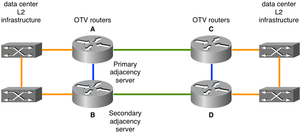
In the topology presented, the links in green are the dark fiber links between the two data centers. These dark fibers are directly attached to the OTV routers. The blue links between the OTV routers are used to reroute non-OTV traffic in the case of a failure of the green links. If the top green link fails (A to C), non-OTV traffic that uses the topmost OTV routers as their default route would be routed via the north-south blue links (A to B and C to D) to the still operational green link between the bottom OTV router pair (B to D).
This basic rerouting of traffic does not work for OTV traffic because the OTV configuration specifies a physical interface as the join interface. If the “green interface” on OTV router A goes down the OTV traffic can not be sourced from an alternate interface OTV router B. Additionally, since there is not full connectivity via the WAN core, all OTV routers can not be informed when there is a failure. In order to get around this problem bidirectional forwarding detection (BFD) along with embedded event manager (EEM) scripting is used.
BFD must monitor the WAN link between the east-west OTV router pairs (A / C and B / D). If connection to the remote router is lost, the OTV Overlay interface is shutdown via the EEM script on that east-west pair of OTV routers. This causes the paired multi-home router to assume forwarding for all VLANs. When BFD detects that the link has recovered, the EEM script triggers to re-enable the Overlay interface.
It is very important that BFD be used to detect link failure. This is because the Overlay interface needs to be shutdown on both the “failed” side as well as it’s east-west pair. Which is contingent on the type of connectivity provided by the service provider, one physical link can go down (green interface on OTV router A) while the the corresponding east-west pair router’s interface can stay up (green interface on OTV router C). BFD detects failure of either interface or any other problem in transit and immediately notify both pairs simultaneously. The same applies to when the routers need to be informed of the recovery link.
The configuration for this deployment is the same as any other deployment with the addition of the subsequent items:
- BFD configuration on the WAN interface
- the subsequent EEM script
- OTV ISIS identity to match even/odd VLAN distribution
Configuration of BFD on the OTV join interface is beyond the scope of this document. Information on how to configure BFD on ASR1000 can be found at:
Once BFD failure detection is operational correctly between the join interface pairs (green links in the diagram), the EEM script must be deployed. The EEM script must be tailored to the specific routers to modify the correct Overlay interfaces as well as perhaps monitor for more exact strings in the log for BFD failure and recovery.
event manager environment _OverlayInt Overlay1
!
event manager applet WatchBFDdown
description "Monitors BFD status, if it goes down, bring OVERLAY int down"
event syslog pattern "BFD peer down notified" period 1
action 1.0 cli command "enable"
action 2.0 cli command "config t"
action 2.1 syslog msg "EEM: WatchBFDdown will shut int $_OverlayInt"
action 3.0 cli command "interface $_OverlayInt"
action 4.0 cli command "shutdown"
action 5.0 syslog msg "EEM WatchBFDdown COMPLETE ..."
!
event manager applet WatchBFDup
description "Monitors BFD status, if it goes up, bring OVERLAY int up"
event syslog pattern "new adjacency" period 1
action 1.0 cli command "enable"
action 2.0 cli command "config t"
action 2.1 syslog msg "EEM: WatchBFDup bringing up int $_OverlayInt"
action 3.0 cli command "interface $_OverlayInt"
action 4.0 cli command "no shutdown"
action 5.0 syslog msg "EEM WatchBFDup COMPLETE ..."
!
This type of deployment also requires that the east-west router pairs (A / C and B / D) match in their forwarding of odd and even vlans.
For example, A and C must forward even VLANs while B and D forward odd VLANs in steady state nominal operation.
The odd / even distribution is determined by the OTV ordinal number which can be observed by the “show otv site” command.
The ordinal number between the two site routers is determined based on the OTV ISIS net ID.
OTV_router_A#show otv site
Site Adjacency Information (Site Bridge-Domain: 99)
Overlay99 Site-Local Adjacencies (Count: 2)
  Hostname       System ID      Last Change Ordinal    AED Enabled Status
* OTV_router_A   0021.D8D4.F200 19:32:02    0          site       overlay
  OTV_router_B   0026.CB0C.E200 19:32:46    1          site       overlay
The OTV ISIS net identifier must be configured on all the OTV routers. Care must be taken when configuration of the identifier such that all OTV routers still recognize each other.
OTV router A:
otv isis Site
net 49.0001.0001.0001.000a.00
OTV router B:
otv isis Site
net 49.0001.0001.0001.000b.00
OTV router C:
otv isis Site
net 49.0001.0001.0001.000c.00
OTV routerD:
otv isis Site
net 49.0001.0001.0001.000d.00
The portions of the identifier in black must match across all OTV routers that participate in the overlay. The portion of the identifier in red can be modified. The lowest network identifier at a site gets ordinal number 0 and in turn forward the even numbered VLANs. The highest network identifier at a site gets ordinal number 1 and forward the odd number VLANs.
Configuration Examples
Unicast
Figure 9. Unicast configuration example
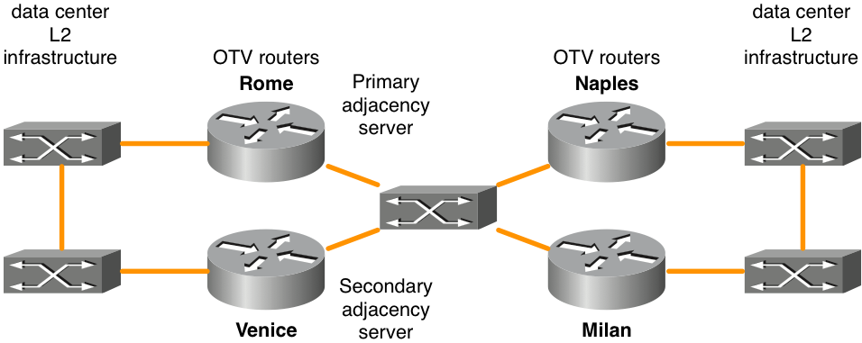
Rome configuration:
!
hostname Rome
!
ip igmp snooping querier version 3
ip igmp snooping querier
!
otv site bridge-domain 99
!
otv site-identifier 0000.0000.0001
!
spanning-tree mode pvst
!
interface Overlay99
 no ip address
 otv join-interface GigabitEthernet1/0/0
 otv adjacency-server unicast-only
 service instance 100 ethernet
  encapsulation dot1q 100
  bridge-domain 100
 !
 service instance 101 ethernet
  encapsulation dot1q 101
  bridge-domain 101
 !
interface GigabitEthernet1/0/0
 ip address 172.16.0.1 255.255.255.0
 negotiation auto
 cdp enable
!
interface GigabitEthernet1/0/1
 no ip address
 negotiation auto
 cdp enable
 service instance 99 ethernet
  encapsulation dot1q 99
  bridge-domain 99
 !
 service instance 100 ethernet
  encapsulation dot1q 100
  bridge-domain 100
 !
 service instance 101 ethernet
  encapsulation dot1q 101
  bridge-domain 101
 !
Venice configuration:
!
hostname Venice
!
ip igmp snooping querier version 3
ip igmp snooping querier
!
otv site bridge-domain 99
!
otv site-identifier 0000.0000.0001
!
spanning-tree mode pvst
!
interface Overlay99
 no ip address
 otv join-interface GigabitEthernet0/0/0
 otv adjacency-server unicast-only
 otv use-adjacency-server 172.16.0.1 unicast-only
 service instance 100 ethernet
  encapsulation dot1q 100
  bridge-domain 100
 !
 service instance 101 ethernet
  encapsulation dot1q 101
  bridge-domain 101
 !
!
interface GigabitEthernet0/0/0
 ip address 172.16.0.2 255.255.255.0
 negotiation auto
 cdp enable
!
interface GigabitEthernet0/0/1
 no ip address
 negotiation auto
 cdp enable
 service instance 99 ethernet
  encapsulation dot1q 99
  bridge-domain 99
 !
 service instance 100 ethernet
  encapsulation dot1q 100
  bridge-domain 100
 !
 service instance 101 ethernet
  encapsulation dot1q 101
  bridge-domain 101
 !
Naples configuration:
!
hostname Naples
!
ip igmp snooping querier version 3
ip igmp snooping querier
!
otv site bridge-domain 99
!
otv site-identifier 0000.0000.0002
!
spanning-tree mode pvst
!
interface Overlay99
 no ip address
 otv join-interface GigabitEthernet0/0/0
 otv use-adjacency-server 172.16.0.1 172.16.0.2 unicast-only
 service instance 100 ethernet
  encapsulation dot1q 100
  bridge-domain 100
 !
 service instance 101 ethernet
  encapsulation dot1q 101
  bridge-domain 101
 !
!
interface GigabitEthernet0/0/0
 ip address 172.16.0.3 255.255.255.0
 negotiation auto
 cdp enable
!
interface GigabitEthernet0/0/1
 no ip address
 negotiation auto
 cdp enable
 service instance 99 ethernet
  encapsulation dot1q 99
  bridge-domain 99
 !
 service instance 100 ethernet
  encapsulation dot1q 100
  bridge-domain 100
 !
 service instance 101 ethernet
  encapsulation dot1q 101
  bridge-domain 101
 !
!
Milan configuration:
!
hostname Milan
!
ip igmp snooping querier version 3
ip igmp snooping querier
!
otv site bridge-domain 99
!
otv site-identifier 0000.0000.0002
!
spanning-tree mode pvst
!
interface Overlay99
 no ip address
 otv join-interface GigabitEthernet0/0/0
 otv use-adjacency-server 172.16.0.1 172.16.0.2 unicast-only
 service instance 100 ethernet
  encapsulation dot1q 100
  bridge-domain 100
 !
 service instance 101 ethernet
  encapsulation dot1q 101
  bridge-domain 101
 !
!
interface GigabitEthernet0/0/0
 ip address 172.16.0.4 255.255.255.0
 negotiation auto
 cdp enable
!
interface GigabitEthernet0/0/1
 no ip address
 negotiation auto
 cdp enable
 service instance 99 ethernet
  encapsulation dot1q 99
  bridge-domain 99
 !
 service instance 100 ethernet
  encapsulation dot1q 100
  bridge-domain 100
 !
 service instance 101 ethernet
  encapsulation dot1q 101
  bridge-domain 101
 !
!
Multicast
Figure 10. Multicast configuration example
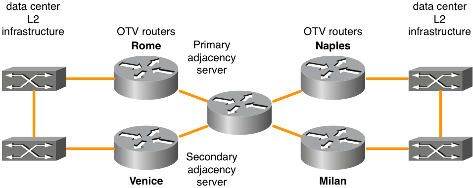
Rome configuration:
!
hostname Rome
!
ip multicast-routing distributed
!
ip igmp snooping querier version 3
ip igmp snooping querier
!
otv site bridge-domain 99
!
otv site-identifier 0000.0000.0001
!
spanning-tree mode pvst
!
interface Overlay99
 no ip address
 otv join-interface GigabitEthernet1/0/0
 otv control-group 239.0.0.1
 otv data-group 238.1.2.0/24
!
 service instance 100 ethernet
  encapsulation dot1q 100
  bridge-domain 100
 !
 service instance 101 ethernet
  encapsulation dot1q 101
  bridge-domain 101
 !
!
interface GigabitEthernet1/0/0
 ip address 192.168.0.1 255.255.255.0
 ip pim passive
 ip igmp version 3
 negotiation auto
 cdp enable
!
interface GigabitEthernet1/0/1
 no ip address
 negotiation auto
 cdp enable
!
 service instance 99 ethernet
  encapsulation dot1q 99
  bridge-domain 99
 !
 service instance 100 ethernet
  encapsulation dot1q 100
  bridge-domain 100
 !
 service instance 101 ethernet
  encapsulation dot1q 101
  bridge-domain 101
 !
Venice configuration:
!
hostname Venice
!
ip multicast-routing distributed
!
ip igmp snooping querier version 3
ip igmp snooping querier
!
otv site bridge-domain 99
!
otv site-identifier 0000.0000.0001
!
spanning-tree mode pvst
!
interface Overlay99
 no ip address
 otv join-interface GigabitEthernet0/0/0
 otv control-group 239.0.0.1
 otv data-group 238.1.2.0/24
 !
 service instance 100 ethernet
  encapsulation dot1q 100
  bridge-domain 100
 !
 service instance 101 ethernet
  encapsulation dot1q 101
  bridge-domain 101
 !
!
interface GigabitEthernet0/0/0
 ip address 172.17.0.1 255.255.255.0
 ip pim passive
 ip igmp version 3
 negotiation auto
 cdp enable
!
interface GigabitEthernet0/0/1
 no ip address
 negotiation auto
 cdp enable
!
 service instance 99 ethernet
  encapsulation dot1q 99
  bridge-domain 99
 !
 service instance 100 ethernet
  encapsulation dot1q 100
  bridge-domain 100
 !
 service instance 101 ethernet
  encapsulation dot1q 101
  bridge-domain 101
 !
Naples configuration:
!
hostname Naples
!
ip multicast-routing distributed
!
ip igmp snooping querier version 3
ip igmp snooping querier
!
otv site bridge-domain 99
!
otv site-identifier 0000.0000.0002
!
spanning-tree mode pvst
!
interface Overlay99
 no ip address
 otv join-interface GigabitEthernet0/0/0
 otv control-group 239.0.0.1
 otv data-group 238.1.2.0/24
!
 service instance 100 ethernet
  encapsulation dot1q 100
  bridge-domain 100
 !
 service instance 101 ethernet
  encapsulation dot1q 101
  bridge-domain 101
 !
!
interface GigabitEthernet0/0/0
 ip address 172.18.0.1 255.255.255.0
 ip pim passive
 ip igmp version 3
 negotiation auto
 cdp enable
!
interface GigabitEthernet0/0/1
 no ip address
 negotiation auto
 cdp enable
 service instance 99 ethernet
  encapsulation dot1q 99
  bridge-domain 99
 !
 service instance 100 ethernet
  encapsulation dot1q 100
  bridge-domain 100
 !
 service instance 101 ethernet
  encapsulation dot1q 101
  bridge-domain 101
 !
!
Milan configuration:
!
hostname Milan
!
ip multicast-routing distributed
!
ip igmp snooping querier version 3
ip igmp snooping querier
!
otv site bridge-domain 99
!
otv site-identifier 0000.0000.0002
!
spanning-tree mode pvst
!
interface Overlay99
 no ip address
 otv join-interface GigabitEthernet0/0/0
otv control-group 239.0.0.1
 otv data-group 238.1.2.0/24
!
  service instance 100 ethernet
  encapsulation dot1q 100
  bridge-domain 100
 !
 service instance 101 ethernet
  encapsulation dot1q 101
  bridge-domain 101
 !
!
interface GigabitEthernet0/0/0
 ip address 172.19.0.1 255.255.255.0
 ip pim passive
 ip igmp version 3
 negotiation auto
 cdp enable
!
interface GigabitEthernet0/0/1
 no ip address
 negotiation auto
 cdp enable
 service instance 99 ethernet
  encapsulation dot1q 99
  bridge-domain 99
 !
 service instance 100 ethernet
  encapsulation dot1q 100
  bridge-domain 100
 !
 service instance 101 ethernet
  encapsulation dot1q 101
  bridge-domain 101
 !
!
Frequently Asked Questions
Q) Are Private VLANs supported in conjunction with OTV?
A) Yes, Not special configuration is required in OTV. In the private VLAN configuration, ensure that the switch ports connected the the OTV L2 interface is configured in promiscuous mode.
Q) Is OTV supported with IPSEC crypto?
A) Yes, Crypto-map configuration on the join-interface is supported. No special configuration is required for OTV to support crypto. However, crypto configuration adds additional overhead and this must be compensated for by the increase of the WAN MTU vs the LAN MTU. If this is not possible, OTV fragmentation must be required. OTV performance is limited to that of the IPSEC hardware.
Q) Is OTV supported with MACSEC?
A) Yes, ASR1001-X includes MACSEC support for the built-in interfaces. OTV works with MACSEC configured on the LAN and/or WAN interfaces. OTV performance is limited to that of the MACSEC hardware.
Q) Can a loopback interface be used as the join interface?
A) No, Only Ethernet, Portchannels, or POS interfaces can be used as OTV join interfaces. OTV Loopback join interface is on the roadmap but is not currently scheduled for a release at this time.
Q) Can a tunnel interface be used as the join interface?
A)No, GRE tunnels, DMVPN tunnels or any other tunnel type are not supported as join interfaces. Only Ethernet, Portchannels, or POS interfaces can be used as OTV join interfaces.
Q) Can different Overlay interfaces use different L2 and/or join interfaces?
A) All Overlay interfaces must point to the same join-interface. All Overlays must be linked to the same physical interface for L2 connectivity towards the data center.
Q) Can the OTV site VLAN be on a different physical interface than the OTV extended VLANs?
A) The OTV site VLAN and extended VLANs must be on the same physical interface.
Q) What feature set is requried for OTV?
A) Advanced IP Services (AIS) or Advanced Enterprise Services (AES) is required for OTV.
Q) Is a separate license required for OTV on fixed configuration platforms?
A) No, As long as the ASR1000 is ran with advipservices or adventerprise boot level configured, OTV is available.
Revision History
| Revision | Publish Date | Comments |
|---|---|---|
1.0 |
31-Jul-2024 |
Initial Release |
Contributed by Cisco Engineers
- David LangleyCisco TAC
Contact Cisco
- Open a Support Case

- (Requires a Cisco Service Contract)
 Feedback