Cisco Long-Reach Ethernet Frequently Asked Questions
Available Languages
Contents
Introduction
This document contains frequently asked questions about the following Cisco Long-Reach Ethernet Products.
-
Cisco 2900 LRE XL switch
-
Cisco 48 LRE POTS splitter
-
Cisco 575 LRE CPE
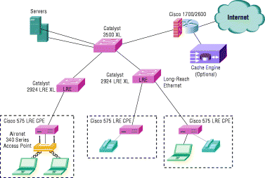
Cisco Long Range Ethernet (LRE) technology dramatically extends Ethernet over existing Category 1/2/3 wiring at speeds from 5 to 15 Mbps (full duplex) and distances up to 5,000 feet. The Cisco LRE technology delivers broadband service on the same lines as Plain Old Telephone Service (POTS), digital telephone, and ISDN traffic. In addition, Cisco LRE supports modes compatible with asymmetric digital subscriber line (ADSL), allowing service providers to provision LRE to buildings where broadband services already exist.
The Cisco LRE solution includes Cisco Catalyst® 2900 LRE XL switches, the Cisco 575 LRE Customer Premises Equipment (CPE) device, and the Cisco LRE 48 POTS Splitter.
For more information about the Cisco LRE, see the Cisco Long-Reach Ethernet Solution data sheet. You can also view the Catalyst 2900 Series Switches Technology Support Pages.

Q. Is it possible to connect two Cisco 575 LRE CPEs back-to-back?
A. No, you cannot connect two Cisco 575 LRE CPEs back-to-back. Also, you cannot connect two Cisco 2900 LRE XL switches back-to-back via the LRE ports.
The Cisco LRE product is a very-high-data-rate digital subscriber line (VDSL) based product so the Transmit (TX) and Receive (RX) use different frequency bands. The Cisco 575 CPE uses the opposite frequency band for transmission/reception compared to the Cisco 2900 LRE XL switch.
Note: There is no crossover cable for this product. The connection must be between the Cisco 575 LRE CPE and the 2900 LRE XL switch.
Q. Are there Media Access Control address restrictions on the Cisco 575 LRE CPE?
A. There are no per port limits on the Cisco 575 LRE CPE device. You may attach an Ethernet hub to the Cisco 575 LRE CPE Ethernet port and connect many PC/laptop clients via the Ethernet hub.
Q. Can I connect the Cisco 575 LRE CPE to an Ethernet hub with multiple PC/laptop clients and if so, what is the maximum number of MAC address entries the Cisco 575 CPE can handle?
A. The Cisco 2900 LRE XL switch has a MAC address space limit of 8192. Each Cisco 575 LRE CPE has a MAC address and when connected to the Cisco 2900 LRE XL switch, will occupy one address space within the Cisco 2900 LRE XL switch address space.
Q. If I have a POTS phone connected to the phone port of my Cisco 575 LRE CPE and I lose power to the CPE, will my POTS phone still work?
A. Yes. The Cisco 575 LRE CPE uses an external power supply. If the Cisco 575 LRE CPE lost power it would not affect the functionality of the attached POTS phone. The POTS service runs passively though the POTS splitter and Cisco 575 LRE CPE and will still operate when the Cisco 2900 LRE XL switch and 575 LRE CPE are not powered on.
Q. Is it possible to attach the multi-key telephone set that uses four wires to a phone key switch via the Cisco 575 LRE CPE and the 2900 LRE XL switch?
A. The Cisco 575 LRE CPE will pass phone and data signaling via the center pair (pair1) of wires 3 and 4. The second outer pair (pair 2) will pass through the CPE unaffected as long as the second pair is connected via the 25-pair cable going to the POTS splitter.
You don't need to run the second pair of wires through the POTS splitter; there will not be LRE data on the second pair.
Q. Can a hotel use a 2-line phone with the Cisco 575 LRE CPE, assuming the two lines are connected to the single phone port of the CPE?
A. Yes. Cisco can support 2-line phones with the Cisco 575 LRE CPE. The 575 LRE CPE uses pins 3 and 4 (pair 1) for the LRE signal and we map pins 2 and 5 (pair 2) and 1 and 6 (pair 3) directly to the same pins on the phone port on the CPE.
When the wiring is done for both lines, make sure that the pair you ran through the splitter in the main distribution frame carries the LRE signal (pins 3 and 4) and then use one of the other pairs (as required by the phone) to support the second line. This line does not need to pass through the splitter since it doesn't carry LRE signals.
Note: Pairs are counted from the inner pair out. This means that pair 1 pins (3 and 4) carry the LRE information. Pair 2 pins (2 and 5) and pair 3 pins (1 and 6) pass through.
Q. Can I POTS-split a digital system that uses 4 wires?
A. Cisco populates all six pins in the RJ-11 jack on both the wall and phone ports on the Cisco 575 LRE CPE. Pins 3 and 4 are used for the LRE signal and map. Pins 1 and 6 and 2 and 5 go directly from the CPE wall jack to the CPE phone jack.
For a 4-line phone system, you need to run one pair through the splitter where the LRE switch is attached and run the second pair directly to the room where the 575 CPE is located. At the room, connect the pair that carries the LRE signal to pins 3 and 4 on the CPE wall jack, and then use one of the other pairs (1 and 6) or (2 and 5) on the CPE wall jack that will carry the POTS/phone service. The LRE will work with all key systems phones as long as they use a frequency below 700 kHz.
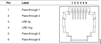
The wall port of the Cisco 575 LRE CPE uses an RJ-11 connector to connect to the LRE signal. The following diagram shows the connector pinouts.

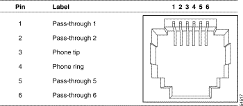
The phone port for the Cisco 575 LRE CPE uses an RJ-11 connector. The following diagram shows the phone port connector pinouts. Note that pins 1, 2, 5, and 6 on the wall port are connected internally to the corresponding pins of the phone port. This allows a second and third phone pair to pass through the CPE without affecting the LRE connection.

Q. Can I reverse pins 3 and 4 on the CPE side of the cable that carries LRE traffic?
A. No. Some single-line and multi-line telephones are sensitive to the polarity inversion between pins 3 and 4 of the CPE wall and phone ports. In these cases, make sure you maintain correct polarity throughout your wiring and connections.
For more information, see Release Notes for the Cisco 575 LRE CPE.
Q. Can I use LRE on the dry copper wire pair?
A. Yes, you can use dry copper wire for LRE traffic only. You would not want to integrate LRE and POTS without using a splitter because you could introduce signaling to POTS that it cannot handle.
Note: Dry copper lines are telephone lines that are not connected to Telco/phone equipment.
Q. What are the correct pinouts for the RJ-21 connector and crossover cable for the Catalyst 2900 LRE XL switch?
A. See Release Notes for the Catalyst 2900 Series XL and Catalyst 3500 Series XL Switches, Cisco IOS Release 12.0(5.4)WC(1) for the correct pinouts. The pinouts shown in the Catalyst 2900 Series XL Hardware Installation Guide are incorrect.
Q. What is the function of the Mode button on the Cisco 2900 LRE XL switch?
A. Catalyst series switches have four LED modes, each of which provides different information about a particular port or about the switch. The Mode button highlights each mode in sequence and is used to select one of the port modes. Changing a port mode changes the information provided by each port status LED. For LED and mode information, see the Product Overview of the Catalyst 2900 Series XL Hardware Installation Guide.
Q. Where can I order cables for connecting a Cisco 2900 LRE XL switch, a Cisco 575 LRE CPE, and a Cisco 48 POTS Splitter?
A. You can order cables from your cable vendor or from your Cisco sales representative.
Connecting the LRE port to a patch panel or POTS splitter requires a male-to-male RJ-21 cable. Cisco offers two types of cables. Each type provides the same functionality but with a different form factor.
The Cisco part numbers for the LRE cables listed in the Catalyst 2900 Series XL Hardware Installation Guide are incorrect. The correct part numbers, documented in Release Notes for the Catalyst 2900 Series XL and Catalyst 3500 Series XL Switches, Cisco IOS Release 12.0(5.4)WC(1), are:
CAB-5-M120M120-5= (Category 5 cable with two 120-degree male-to-male RJ-21 connectors)
CAB-5-M180M120-5= (Category 5 cable with one 180-degree and one 120-degree male-to-male RJ-21 connector)
Depending on the model of the switch, you can connect the LRE port to either 12 or 24 Cisco 575 LRE CPE devices through a patch panel. If no other telephone services use the same wiring as LRE traffic, the LRE switch connects directly to the patch panel. If telephone services such as voice or ISDN do use the same cabling as LRE traffic, you must connect the LRE to a POTS splitter. The following URLs have information that will also be helpful:
Q. Can I use LRE and xDSL on the same 50-wire cable bundle?
A. LRE can exist in the same 50-wire bundle with xDSL when LRE public profiles are used.
Bandwidth within the LRE link is controlled by the switch by using configurations called profiles. An LRE profile configures the upstream and downstream rates on the LRE link. The Catalyst 2900 LRE XL switches are shipped with predefined profiles, categorized as public (global) mode and private (per-port) mode. By default, all LRE ports on the switch are enabled with the LRE-10 private profile.
LRE and xDSL cannot coexist on the same wire because they share the same frequencies. Note that if the xDSL signal is "noisy" it may cause crosstalk. Even if it's running on another pair of wires in the same bundle as the LRE cicuit, it could limit the reach of the LRE devices.
Q. Should I use homologated or Cisco's nonhomologated POTS splitter to install my Cisco LRE equipment if telephone services are sent directly to a PSTN?
A. For installations where telephone services will be routed to a private branch exchange (PBX) switch, you can install a Cisco LRE POTS Splitter (PS-1M-LRE-48). For more information about this POTS splitter, refer to the Installation Notes for the Cisco LRE 48 POTS Splitter.
If the building does not use a PBX and telephone services are sent directly to an outside public-switched telephone network (PSTN, you need to use a homologated POTS splitter. For more information about homologated POTS splitters, contact your Cisco sales representative. For more information about installing a Catalyst 2900 LRE XL switch, refer to the Catalyst 2900 Series XL Hardware Installation Guide.
The Cisco LRE 48 POTS Splitter, also referred to as the splitter, is a set of filters used in installations where LRE traffic shares telephone lines with existing voice, ISDN, or Smart Phone services. The splitter separates the LRE traffic from the other phone services, sending the high-frequency LRE traffic to a Cisco Catalyst 2900 LRE XL switch and the low-frequency telephone services to a PBX switch. No configuration of the splitter is necessary. After the devices are connected to the splitter, it automatically separates the LRE and telephone traffic.
The Cisco LRE 48 POTS Splitter is a nonhomologated splitter and is not certified for connection to a PSTN. Connecting the splitter directly to a PSTN can damage the splitter. If telephone services will be sent directly to a PSTN, you need to use a homologated POTS splitter. For more information about homologated POTS splitters, contact your Cisco sales representative.
Q. Can the Cisco 2900 LRE XL switch with a Cisco 48 LRE POTS splitter work with a digital PBX?
A. The LRE POTS will work with a digital PBX if you stay within the pass band. The pass band for the POTS ports is 10-700 kHz; the stop band is 900 kHz – 7.9 MHz.
The LRE POTS will work with all key systems phones as long as they use a frequency below 700 kHz.
Q. If I do not use a POTS splitter, how do I connect my Cisco 2900 LRE XL switch to the Cisco 575 CPE?
A. If a phone network connection isn't required, you don't need a splitter. The Cisco 2900 LRE XL switch and the 575 LRE CPE can connect directly to the patch panel.
To connect to an LRE port, see Where can I order cables for connecting a Cisco 2900 LRE XL switch, a Cisco 575 LRE CPE, and a Cisco 48 POTS Splitter?.
Q. How do I upgrade the firmware on the Cisco 575?
A. Firmware was installed during manufacturing and new firmware is not yet available. When new firmware is needed, Cisco will release a new version of Cisco IOS® software for the Cisco 2900 LRE XL switch that will provide a method for upgrading the firmware on the Cisco 575.
Q. How do I find out the software versions that are running on the Cisco 2900 LRE XL switch and the 575 LRE CPE?
A. Issue the show controller lre version command from the console of the Cisco 2900 LRE XL switch. The software version displays. For example:
--- SWITCH --  ---- CPE ----
Interface   Hw Sw Patch    Hw Sw Patch
Lo0/1       32 B4 50       32 B4 50
Q. How do I upgrade the Cisco 2900 LRE XL switch?
Q. What could cause a throughput problem on my PC client when it's connected to the Cisco 575 LRE CPE?
A. If the PC client attached to the Cisco 575 LRE CPE does not support full-duplex flow control, you cannot use the full duplex setting configured on the Cisco 2900 LRE port. Change the duplex setting on the Cisco 2900 LRE port to half duplex and test again. You can also test with the Cisco 2900 LRE port set to 10 Mbps and full-duplex.
The Cisco 575 CPE Ethernet port defaults to half-duplex so that it can force collisions when it wants the PC client to slow down. There is very little buffering on the Cisco 575, so when you have a 100 Mbps connection going into a 15 Mbps pipe, you are going to lose packets unless the PC client Ethernet adapter is in half-duplex mode or supports flow control. The Cisco 575 CPE Ethernet port can be configured for full duplex flow control via the Cisco 2900 LRE port, but if the attached PC doesn't understand flow control, use half duplex. Due to the LRE link limitation of 15 Mbps, you won't see a performance difference between 100 Mbps/half and 100 Mbps/full.
Upstream data is trying to go faster than the CPE and LRE link can handle so packets are either being dropped or the windowing size is dropped to a level that the LRE link and CPE can manage. On the switch side, buffering occurs for the file download so you don't see this issue. Plus, the switch software is able to automatically set the duplex mode to "half" or "full" between the switch and the LRE line, regardless of the CPE setting.
Q. Where can I find a Cisco document about connecting the Cisco 2900 LRE XL switch to other devices?
A. The Connectors and Cable Specifications document describes the switch ports and the cables and adapters used to connect the switch to other devices.
Q. Where do I find MIB information for the Cisco 2900 LRE XL switch?
A. Management Information Base (MIB) information can be found in the Cisco Documentation and Release notes on the Cisco Web site. The following documents provide MIB information:
Related Information
Contact Cisco
- Open a Support Case

- (Requires a Cisco Service Contract)


 Feedback