Configure OSPFv3 as PE-CE Protocol with Loop Prevention Techniques
Available Languages
Download Options
Bias-Free Language
The documentation set for this product strives to use bias-free language. For the purposes of this documentation set, bias-free is defined as language that does not imply discrimination based on age, disability, gender, racial identity, ethnic identity, sexual orientation, socioeconomic status, and intersectionality. Exceptions may be present in the documentation due to language that is hardcoded in the user interfaces of the product software, language used based on RFP documentation, or language that is used by a referenced third-party product. Learn more about how Cisco is using Inclusive Language.
Contents
Introduction
This document describes the loop prevention features and the minimum configuration steps when you run the Open Shortest Path First version 3 (OSPFv3) as Internet Protocol version 6 (IPv6) routing protocol between Provider Edge (PE) and Customer Edge (CE) routers. It presents a network scenario that depicts the use of Downward Bit (DN), which is an option in the Link State Advertisement (LSA). It also shows how loop prevention checks differ from Open Shortest Path First version 2 (OSPFv2).
Prerequisites
Requirements
Cisco recommends that you have knowledge of these topics:
- OSPFv3
- Multiprotocol Label Switching (MPLS) Layer 3 VPN.
Components Used
This document is not restricted to specific software and hardware versions.
The information in this document was created from the devices in a specific lab environment. All of the devices used in this document started with a cleared (default) configuration. If your network is live, make sure that you understand the potential impact of any command.
Background Information
The Service Provider (SP) and the CE router exchange routes with a routing protocol to which the SP and customer jointly agree. The scope of this document is to describe the loop-prevention mechanism when OSPFv3 is used.
When OSPFv3 is used on a PE-CE link that belongs to a particular Virtual Routing and Forwarding (VRF) or VPN, the PE router:
- Redistributes the IPv6 routes received via OSPFv3 for that VRF into Multiprotocol-Border Gateway Protocol (MP-BGP) and advertises VPNv6 routes to the other PE routers.
- Redistributes the VPNv6 routes installed in the VRF via MP-BGP into the OSPFv3 instance for that VRF and advertises it to the CE Routers.
Configure
Network Diagram
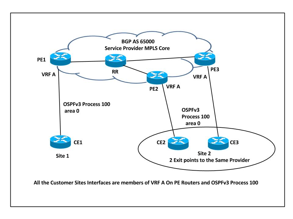
This image illustrates the loop-prevention techniques. 
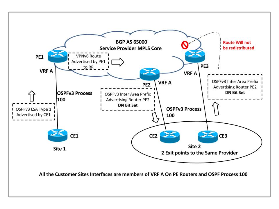
In this setup, there is a possibility of a loop. For example, if CE1 advertises the OSPFv3 LSA Type 1 to PE1, which redistributes the route into VPNv6 and advertises it to PE2, then PE2 in turn advertises the Inter-Area-Prefix LSA to CE2.
This route received by CE2 could be advertised back to PE3. PE3 learns the OSPF route, which is better than the BGP route, and readvertises the route into BGP as local to the customer site 2.
PE3 never learns that the route that was advertised was not originated from customer site 2.
In order to overcome this situation, when the routes are redistributed from MP-BGP into OSPFv3, they are marked with a DN Bit in LSA Type 3 and Type 5.
Configuration
Here is the sample configuration on PE routers. This configuration includes the VRF configuration, the OSPFv3 Process 100 that runs between the PE-CE routers, the OSPF Process 10 that runs as Interior Gateway Protocol (IGP) in the MPLS core and the MP-BGP configuration for VPNv6 Peering.
vrf definition A
 rd 65000:100
 !
 address-family ipv4
 route-target export 65000:100
 route-target import 65000:100
 exit-address-family
 !
 address-family ipv6
 route-target export 65000:100
 route-target import 65000:100
 exit-address-family

! VRF A configuration with Route Distinguisher and Route Targets
interface Ethernet0/0
 vrf forwarding A
 no ip address
 ipv6 address 2002:123:123:11::2/64
 ospfv3 100 ipv6 area 0

! Eth0/0 Interface - CE1 Facing
router ospf 10
 router-id 172.16.0.1
 network 172.16.0.1 0.0.0.0 area 0
 network 192.168.14.1 0.0.0.0 area 0

! OSPF Process 10 running in MPLS Core and Loopback 0
router ospfv3 100
 !
 address-family ipv6 unicast vrf A
 redistribute bgp 65000
 router-id 172.16.123.4
 exit-address-family

! OSPFv3 100 Configuration for VRF A and redistribution of VPNv6 routes into OSPFv3
router bgp 65000
 bgp log-neighbor-changes
 no bgp default ipv4-unicast
 neighbor 172.16.0.4 remote-as 65000
 neighbor 172.16.0.4 update-source Loopback0
 !
 address-family ipv4
 exit-address-family
 !
 address-family vpnv6
 neighbor 172.16.0.4 activate
 neighbor 172.16.0.4 send-community both
 exit-address-family
 !
 address-family ipv6 vrf A
 redistribute ospf 100 match internal external 1 external 2 include-connected
 exit-address-family

! BGP VPNv6 configuration and Redistribution of OSPF Process 100 into BGP, so that the routes are advertised as VPNV6 prefixes
DN Bit
The previously unused bit in the OSPF LSA Options field is referred to as the DN Bit. This bit is set on Type 3 and Type 5 LSA when the MP-BGP VPNv6 routes are redistributed into OSPFv3. When the other PE Routers receive the LSA from a CE router with the DN Bit set, the information from that LSA is not used in the OSPF route calculation.

Based on the network topology, PE2 sets the DN Bit for the redistributed LSA and this LSA is never considered for route calculation in OSPF Process 100 on PE3. So PE3 never redistributes this route back into MP-BGP.
For OSPFv3, each prefix is advertised along with an 8-bit field of capabilities. These serve as input to the various routing calculations. The format for this field in LSA Header is shown.
                     0  1  2  3  4  5  6  7
                    +--+--+--+--+--+--+--+--+
                    |  |  |  |DN| P|x |LA|NU|
                    +--+--+--+--+--+--+--+--+
                     The PrefixOptions Field

The DN-Bit controls an inter-area-prefix-LSAs or AS-external-LSAs re-advertisement in a VPN environment
Here is an example of the OSPFv3 Header that shows the DN Bit Set, when the route was advertised by PE Router for Inter-Area-Prefix LSA:
 Internet Protocol Version 6
 0110 .... = Version: 6
 .... 1100 0000 .... .... .... .... .... = Traffic class: 0x000000c0
 .... .... .... 0000 0000 0000 0000 0000 = Flowlabel: 0x00000000
 Payload length: 64
 Next header: OSPF IGP (0x59)
 Hop limit: 1
 Source: fe80::a8bb:ccff:fe00:600 (fe80::a8bb:ccff:fe00:600)
 Destination: ff02::5 (ff02::5)

 Open Shortest Path First
   OSPF Header
   OSPF Version: 3
   Message Type: LS Update (4)
   Packet Length: 64
   Source OSPF Router: 172.16.123.5 (172.16.123.5)
   Area ID: 0.0.0.0 (Backbone)
   Packet Checksum: 0xe042 [correct]
   Instance ID: 0 (IPv6 unicast AF)
   Reserved: 0

 LS Update Packet
   Number of LSAs: 1
   Inter-Area-Prefix-LSA (Type: 0x2003)
   LS Age: 1 seconds
   Do Not Age: False
   LSA Type: 0x2003 (Inter-Area-Prefix-LSA)
   Link State ID: 0.0.0.6
   Advertising Router: 172.16.123.5 (172.16.123.5)
   LS Sequence Number: 0x80000001
   LS Checksum: 0x12af
   Length: 44
   Reserved: 0
   Metric: 10
   PrefixLength: 128
   PrefixOptions: 0x10 ()
   Reserved: 0
   Address Prefix: 2002:123:123:123::1
Verify
The commands to discover if the DN Bit is set for the LSA are same that are used in order to check the OSPFv3 LSA database.
This output shows the example for OSPFv3 Inter-Area-Prefix LSA and AS External LSA and highlights the DN Bit set.
CE2#sh ipv6 ospf database inter-area prefix 2002:123:123:123::1/128

              OSPFv3 Router with ID (172.16.123.2) (Process ID 100)

 Routing Bit Set on this LSA
 LS age: 11
 LS Type: Inter Area Prefix Links
 Link State ID: 6
 Advertising Router: 172.16.123.5
 LS Seq Number: 80000001
 Checksum: 0x12AF
 Length: 44
 Metric: 10
 Prefix Address: 2002:123:123:123::1
 Prefix Length: 128, Options: DN

CE2#sh ipv6 ospf database external 2002:123:123:123::123/128

               OSPFv3 Router with ID (172.16.123.2) (Process ID 100)

                       Type-5 AS External Link States

 Routing Bit Set on this LSA
 LS age: 83
 LS Type: AS External Link
 Link State ID: 0
 Advertising Router: 172.16.123.5
 LS Seq Number: 80000001
 Checksum: 0x294B
 Length: 44
 Prefix Address: 2002:123:123:123::123
 Prefix Length: 128, Options: DN
 Metric Type: 2 (Larger than any link state path)
 Metric: 20
Note: MPLS VPN OSPF PE-CE always includes the loop-prevention mechanism in order to handle issues. In the older Cisco IOS®, the per original IETF draft Type 3 LSAs use the DN Bit in LSA and Type 5 LSAs use a tag. The newer RFC 4576 mandates use of DN Bit for both Type 3 and Type 5 LSAs.
This was committed via Cisco bug ID t for OSPFv2. For OSPFv3 support of tags added no advantage, so OSPFv3 does not set or check domain tags.
Troubleshoot
There is currently no specific troubleshooting information available for this configuration.
Contributed by Cisco Engineers
Contact Cisco
- Open a Support Case

- (Requires a Cisco Service Contract)
 Feedback