Constraining Multicast Traffic with Source and Receivers on the Same VLAN on Catalyst Switches Running Catalyst OS
Available Languages
Contents
Introduction
Network managers frequently ask whether it is possible to constrain multicast traffic on a switch when the multicast source and the multicast receivers are all on the same VLAN, and what the requirements are for accomplishing this goal—in particular, whether a router is required.
The answer is yes it is possible, and in most cases a router is required.
Note: Starting from CatOS 7.1 and later versions on the Catalyst 6500/6000 series switches, a new feature is available called the Internet Group Management Protocol (IGMP) snooping querier. With this feature, a router is no longer required to constrain multicast traffic when the multicast source and all receivers are in the same VLAN. The IGMP snooping querier enables IGMP snooping within a VLAN where Protocol Independent Multicast (PIM) and IGMP are not configured because the multicast traffic does not need to be routed.
Prerequisites
Requirements
Readers of this document should be knowledgeable of the following:
-
The basic requirements for constraining multicast traffic on a switch when the multicast source and all receivers are in the same VLAN are as follows:
-
The switch must have Cisco Group Management Protocol (CGMP) or Internet Group Management Protocol (IGMP) snooping enabled. GARP Multicast Registration Protocol (GMRP), another mechanism for constraining multicast on Layer 2 devices, is not considered here.
-
The router must have Protocol-Independent Multicast (PIM) enabled on the interface connected in the VLAN where the source and receivers are located.
-
If you are using CGMP, the router must have CGMP enabled on the interface connected in the VLAN where the source and receivers are located.
Note: You do not have to enable multicast routing (using the ip multicast-routing global configuration command) on the router if you just want to constrain multicasts on a single VLAN and you do not intend for multicast traffic to be forwarded to other interfaces or subnets (the router will complain that you must enable multicast routing when you enable PIM on the router interface but this warning can be safely ignored in this application).
-
-
This document explains constraining multicast traffic on Catalyst switches running CatOS. Refer to the following documents to constrain multicast traffic on Catalyst 4000 and 6000 switches running Cisco IOS® system software (Native Mode):
-
Understanding and Configuring IGMP Snooping on Catalyst 4000
-
Configuring IGMP Snooping on Catalyst 6500/6000
-
Components Used
To create the examples in this document, the following devices were used in a lab environment:
-
Catalyst 4908G-L3 switch-router running Cisco IOS 12.0(7)W5(15d)
-
Catalyst 4003 switch running Catalyst OS 5.5(2)
-
Catalyst 6009 switch running Catalyst OS 5.5(2)
-
Catalyst 5509 switch running Catalyst OS 5.5(2)
-
For the IGMP Snooping Querier feature, two catalyst 6500/6000 series switches running 8.1(3) and 7.6(2a)
-
Two additional routers (in this case a Catalyst 2948G-L3 and a Cisco 7000) acting as multicast receivers (hosts)
-
A traffic generator (SmartBits 2000) capable of transmitting IP multicast streams
The information in this document was created from the devices in a specific lab environment. All of the devices used in this document started with a cleared (default) configuration. If your network is live, make sure that you understand the potential impact of any command.
Related Products
CGMP and IGMP snooping are supported on the Catalyst switches as follows:
-
Catalyst 4000 family: CGMP only
-
Catalyst 6000 family: IGMP snooping only
-
Catalyst 5000 family: IGMP snooping (with Supervisor Engine III/IIIF with NFFC or NFFC II, or with Supervisor Engine IIG/IIIG) and CGMP
See the multicast documentation for the Catalyst 4000/5000 and Catalyst 6000 for more information, including specific hardware and software requirements.
The configurations in this document were implemented in an isolated lab environment. Ensure that you understand the potential impact of any configuration or command on your network before using it.
Conventions
For more information on document conventions, see the Cisco Technical Tips Conventions.
Configuration Using CGMP
This example shows a basic network environment where multicast source(s) and multicast receivers are in the same VLAN. The desired behavior is that the switch will constrain the multicast forwarding to only those ports that request the multicast stream.
The network topology for this example is shown in Figure 1.
Figure 1: CGMP Example Part 1 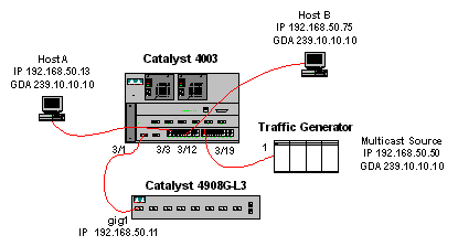
The traffic generator is sending a 1 Mbps stream of multicast UDP packets to the group address 239.10.10.10 on VLAN 50 (port 3/19 of the Catalyst 4003).
The 4908G-L3 router is connected to the Catalyst 4003 on port 3/1 in VLAN 50. The following configuration is applied on the GigabitEthernet1 interface (note that there is not an ip multicast-routing command configured globally, because the router is not routing multicast traffic across its interfaces):
interface GigabitEthernet1
 ip address 192.168.50.11 255.255.255.0
 ip pim dense-mode
 ip cgmp
The Catalyst 4003 switch has CGMP and CGMP fastleave enabled ( set cgmp enable and set cgmp leave enable ).
There are two hosts (multicast receivers) connected to the Catalyst 4003. Host A is connected on port 3/3 in VLAN 50. Host B is connected on port 3/12 on VLAN 50. These hosts are actually routers configured as end stations (that is, no routing or other similar functions are configured). Host A has an interface configured with IP address 192.168.50.13/24, while Host B has an interface configured with IP address 192.168.50.75/24. Later in this example, the hosts will be joined into the multicast group using the ip igmp join-group interface configuration command.
The following output is from the Catalyst 4908G-L3 when the traffic generator is transmitting to the group address 239.10.10.10 in VLAN 50 but there are no receivers on the switch:
4908g-l3# show ip pim interface

Address          Interface          Version/Mode    Nbr   Query     DR
                                                    Count Intvl
192.168.50.11    GigabitEthernet1   v2/Dense         0    30     192.168.50.11
4908g-l3#show ip igmp interface gig 1
GigabitEthernet1 is up, line protocol is up
  Internet address is 192.168.50.11/24
  IGMP is enabled on interface
  Current IGMP version is 2
  CGMP is enabled on interface
  IGMP query interval is 60 seconds
  IGMP querier timeout is 120 seconds
  IGMP max query response time is 10 seconds
  Last member query response interval is 1000 ms
  Inbound IGMP access group is not set
  IGMP activity: 2 joins, 1 leaves
  Multicast routing is enabled on interface
  Multicast TTL threshold is 0
  Multicast designated router (DR) is 192.168.50.11 (this system)
  IGMP querying router is 192.168.50.11 (this system)
  Multicast groups joined: 224.0.1.40
queue_counter 2579 periodic_counter 77065 dmvrp_counter 0 timer_couter 77065 ast
ray 0
4908g-l3# show ip mroute
IP Multicast Routing Table
Flags: D - Dense, S - Sparse, C - Connected, L - Local, P - Pruned
       R - RP-bit set, F - Register flag, T - SPT-bit set, J - Join SPT
       X - Proxy Join Timer Running
       Outgoing Interface Flags: H - Hardware switched
Timers: Uptime/Expires
Interface state: Interface, Next-Hop or VCD, State/Mode

(*, 239.10.10.10), 00:02:15/00:02:59, RP 0.0.0.0, flags: DJC
  Incoming interface: Null, RPF nbr 0.0.0.0
  Outgoing interface list:
    GigabitEthernet1, Forward/Dense, 00:02:15/00:00:00

(192.168.50.50, 239.10.10.10), 00:02:16/00:00:43, flags: PCT
  Incoming interface: GigabitEthernet1, RPF nbr 0.0.0.0
  Outgoing interface list: Null

4908g-l3#
Notice the output in bold type:
-
The show ip pim interface output shows that the GigabitEthernet1 interface with IP address 192.168.50.11 is running PIM-DenseMode (PIM-DM).
-
The show ip igmp interface gig 1 command shows that IGMP and CGMP are enabled on the interface and that PIM is running on the interface.
-
The show ip mroute command shows that the router has a (source, group) entry for 239.10.10.10, sourced from 192.168.50.50 (the traffic generator). Notice that the outgoing interface list is Null. This is because the router is not actually performing multicast routing across its interfaces. It is only serving to monitor IGMP joins and leaves in VLAN 50, and to send CGMP messages to the switch.
The following output is from the Catalyst 4003 switch where the traffic generator is transmitting to the group address 239.10.10.10 in VLAN 50 but there are no receivers on the switch:
4003> (enable) show cgmp leave

CGMP:       enabled
CGMP leave: enabled
4003> (enable) show multicast router
Port       Vlan
---------- ----------------
 3/1       50

Total Number of Entries = 1
'*' - Configured
'+' - RGMP-capable
4003> (enable) show multicast group
VLAN  Dest MAC/Route Des    [CoS]  Destination Ports or VCs / [Protocol Type]
----  ------------------    -----  -------------------------------------------
50    01-00-5e-00-01-28             3/1
50    01-00-5e-0a-0a-0a             3/1

Total Number of Entries = 2
4003> (enable)
Notice the output in bold type:
-
The show cgmp leave output shows that CGMP and CGMP fast leave are enabled on the switch.
-
The show multicast router command shows that the switch is aware of one multicast router on port 3/1 in VLAN 50 (the 4908G-L3).
-
The show multicast group command shows that the switch is constraining traffic destined to MAC address 01-00-5e-0a-0a-0a (the multicast MAC address to which 239.10.10.10 maps) in VLAN 50 to just port 3/1, the multicast router port.
Now, configure Host A and Host B as multicast receivers for group address 239.10.10.10. This is accomplished using the ip igmp join-group interface configuration command.
Host A (a Catalyst 2948G-L3 connected on the FastEthernet13 interface):
HostA# configure terminal
Enter configuration commands, one per line.  End with CNTL/Z.
HostA(config)# interface fastethernet13
HostA(config-if)# ip igmp join-group 239.10.10.10
HostA(config-if)# ^Z
HostA# show ip igmp group
IGMP Connected Group Membership
Group Address    Interface            Uptime    Expires   Last Reporter
239.10.10.10     FastEthernet13       00:00:05  never     192.168.50.13
HostA#
Host B (a Cisco 7000 connected on the Ethernet1/0 interface):
HostB# configure terminal
Enter configuration commands, one per line.  End with CNTL/Z.
HostB(config)# interface ethernet1/0
HostB(config-if)# ip igmp join-group 239.10.10.10
HostB(config-if)# ^Z
HostB# show ip igmp group
IGMP Connected Group Membership
Group Address    Interface            Uptime    Expires   Last Reporter
239.10.10.10     Ethernet1/0          00:00:10  never     192.168.50.75
HostB#
The following output is from the Catalyst 4003 switch after Host A and Host B have joined the multicast group 239.10.10.10:
4003> (enable) show multicast group
VLAN  Dest MAC/Route Des    [CoS]  Destination Ports or VCs / [Protocol Type]
----  ------------------    -----  -------------------------------------------
50    01-00-5e-00-01-28             3/1
50    01-00-5e-0a-0a-0a             3/1,3/3,3/12

Total Number of Entries = 2
4003> (enable)
Notice that the switch is now forwarding traffic for 01-00-5e-0a-0a-0a (239.10.10.10) on ports 3/3 (Host A) and 3/12 (Host B) in VLAN 50.
Now Host A leaves the multicast group:
HostA# configure terminal
Enter configuration commands, one per line.  End with CNTL/Z.
HostA(config)# interface fastethernet13
HostA(config-if)# no ip igmp join-group 239.10.10.10
HostA(config-if)# ^Z
HostA#
The switch removes port 3/3 from the multicast forwarding table for 01-00-5e-0a-0a-0a:
4003> (enable) show multicast group
VLAN  Dest MAC/Route Des    [CoS]  Destination Ports or VCs / [Protocol Type]
----  ------------------    -----  -------------------------------------------
50    01-00-5e-00-01-28             3/1
50    01-00-5e-0a-0a-0a             3/1,3/12

Total Number of Entries = 2
4003> (enable)
Now, the traffic generator begins sending an additional 1 Mbps multicast stream destined for 239.85.85.85 (MAC address 01-00-5e-55-55-55). See Figure 2.
Figure 2: CGMP Example Part 2 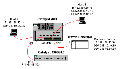
The following output shows the multicast routing table on the Catalyst 4908G-L3:
4908g-l3# show ip mroute
IP Multicast Routing Table
Flags: D - Dense, S - Sparse, C - Connected, L - Local, P - Pruned
       R - RP-bit set, F - Register flag, T - SPT-bit set, J - Join SPT
       X - Proxy Join Timer Running
       Outgoing Interface Flags: H - Hardware switched
Timers: Uptime/Expires
Interface state: Interface, Next-Hop or VCD, State/Mode

(*, 239.85.85.85), 00:01:35/00:02:59, RP 0.0.0.0, flags: DP
  Incoming interface: Null, RPF nbr 0.0.0.0
  Outgoing interface list: Null

(192.168.50.50, 239.85.85.85), 00:01:36/00:01:23, flags: PT
  Incoming interface: GigabitEthernet1, RPF nbr 0.0.0.0
  Outgoing interface list: Null

(*, 239.10.10.10), 00:01:36/00:02:59, RP 0.0.0.0, flags: DP
  Incoming interface: Null, RPF nbr 0.0.0.0
  Outgoing interface list: Null

(192.168.50.50, 239.10.10.10), 00:01:36/00:01:23, flags: PT
  Incoming interface: GigabitEthernet1, RPF nbr 0.0.0.0
  Outgoing interface list: Null

4908g-l3#
Notice that there is an (S,G) and a (*,G) entry for each multicast stream.
On the Catalyst 4003, the multicast forwarding table looks like this:
4003> (enable) show multicast group
VLAN  Dest MAC/Route Des    [CoS]  Destination Ports or VCs / [Protocol Type]
----  ------------------    -----  -------------------------------------------
50    01-00-5e-00-01-28             3/1
50    01-00-5e-0a-0a-0a             3/1,3/12
50    01-00-5e-55-55-55             3/1

Total Number of Entries = 3
4003> (enable)
Notice that the switch has added an entry for 01-00-5e-55-55-55 on port 3/1 (the router port) in VLAN 50.
Now, Host A and Host B both join the 239.85.85.85 group using the ip igmp join-group 239.85.85.85 interface configuration command. Here is the switch multicast forwarding table after Host A and Host B join the group:
4003> (enable) show multicast group
VLAN  Dest MAC/Route Des    [CoS]  Destination Ports or VCs / [Protocol Type]
----  ------------------    -----  -------------------------------------------
50    01-00-5e-00-01-28             3/1
50    01-00-5e-0a-0a-0a             3/1,3/12
50    01-00-5e-55-55-55             3/1,3/3,3/12

Total Number of Entries = 3
4003> (enable)
Notice that the switch has added ports 3/3 and 3/12 in the entry for 01-00-5e-55-55-55 in VLAN 50.
Configuration Using IGMP Snooping
This example shows another basic network environment where multicast source(s) and multicast receivers are all in the same VLAN. The desired behavior is that the switches will constrain the multicast forwarding to only those ports that request the multicast stream.
The network topology for this example is shown in Figure 3.
Figure 3: IGMP Snooping Example Part 1 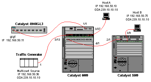
The traffic generator is sending a 1 Mbps stream of multicast UDP packets to the group address 239.10.10.10 on VLAN 50 (port 3/13 of the Catalyst 6009).
The 4908G-L3 router is connected to the Catalyst 6009 on port 1/1. The link is configured as a VLAN trunk. The following configuration is applied on the GigabitEthernet1.50 sub-interface (note that there is not an ip multicast-routing command configured globally, because the router is not routing multicast traffic across its interfaces):
interface GigabitEthernet1.50
 encapsulation isl 50
 ip address 192.168.50.11 255.255.255.0
 ip pim dense-mode
Notice that the ip cgmp interface configuration command is not required when you are using only IGMP snooping on the Layer 2 switches.
The Catalyst 6009 and the Catalyst 5509 switches have IGMP snooping and IGMP fast leave enabled ( set igmp enable and set igmp fastleave enable ). The Catalyst 6009 connects via a trunk link on port 4/1 to the Catalyst 5509 on port 2/1.
There are two hosts (multicast receivers) in this example. Host A is connected to the Catalyst 6009 on port 3/37 in VLAN 50. Host B is connected to the Catalyst 5509 on port 3/9 in VLAN 50. As in the CGMP example, these hosts are actually routers configured as end stations (that is, no routing or other similar functions are configured). Host A has an interface configured with IP address 192.168.50.13/24, while Host B has an interface configured with IP address 192.168.50.75/24. Later in this example, the Hosts will be joined into the multicast group using the ip igmp join-group interface configuration command.
The following output is from the Catalyst 4908G-L3 when the traffic generator is transmitting to the group address 239.10.10.10 in VLAN 50 but there are no receivers on the switch:
4908g-l3# show ip pim interface

Address          Interface          Version/Mode    Nbr   Query     DR
                                                    Count Intvl
192.168.50.11    Gi1.50             v2/Dense         0    30     192.168.50.11
4908g-l3# show ip igmp interface gig1.50
Gi1.50 is up, line protocol is up
  Internet address is 192.168.50.11/24
  IGMP is enabled on interface
  Current IGMP version is 2
  CGMP is disabled on interface
  IGMP query interval is 60 seconds
  IGMP querier timeout is 120 seconds
  IGMP max query response time is 10 seconds
  Last member query response interval is 1000 ms
  Inbound IGMP access group is not set
  IGMP activity: 3 joins, 2 leaves
  Multicast routing is enabled on interface
  Multicast TTL threshold is 0
  Multicast designated router (DR) is 192.168.50.11 (this system)
  IGMP querying router is 192.168.50.11 (this system)
  Multicast groups joined: 224.0.1.40
queue_counter 85 periodic_counter 4777 dmvrp_counter 0 timer_couter 4777 astray
0
4908g-l3# show ip mroute
IP Multicast Routing Table
Flags: D - Dense, S - Sparse, C - Connected, L - Local, P - Pruned
       R - RP-bit set, F - Register flag, T - SPT-bit set, J - Join SPT
       X - Proxy Join Timer Running
       Outgoing Interface Flags: H - Hardware switched
Timers: Uptime/Expires
Interface state: Interface, Next-Hop or VCD, State/Mode

(*, 239.10.10.10), 00:02:10/00:02:59, RP 0.0.0.0, flags: DP
  Incoming interface: Null, RPF nbr 0.0.0.0
  Outgoing interface list: Null

(192.168.50.50, 239.10.10.10), 00:02:11/00:00:48, flags: PT
  Incoming interface: GigabitEthernet1.50, RPF nbr 0.0.0.0
  Outgoing interface list: Null

4908g-l3#
The output in bold is explained in further detail below.
-
The show ip pim interface output shows that the GigabitEthernet1 interface with IP address 192.168.50.11 is running PIM-DenseMode (PIM-DM).
-
The show ip igmp interface gig 1.50 command shows that IGMP is enabled and CGMP is disabled on the interface, and that PIM is running on the interface.
-
The show ip mroute command shows that the router has a (source, group) entry for 239.10.10.10, sourced from 192.168.50.50 (the traffic generator). Notice that the outgoing interface list is Null. This is because the router is not actually performing multicast routing across its interfaces. It is only serving to monitor IGMP joins and leaves in VLAN 50.
The following output is from the Catalyst 6009 switch where the traffic generator is transmitting to the group address 239.10.10.10 in VLAN 50 but there are no receivers on the switch:
Cat6009> (enable) show multicast protocols status
IGMP enabled
IGMP fastleave enabled
RGMP disabled
GMRP disabled
Cat6009> (enable) show multicast router
Port       Vlan
---------- ----------------
 1/1       50

Total Number of Entries = 1
'*' - Configured
'+' - RGMP-capable
Cat6009> (enable) show multicast group
VLAN  Dest MAC/Route Des    [CoS]  Destination Ports or VCs / [Protocol Type]
----  ------------------    -----  -------------------------------------------
50    01-00-5e-00-01-28             1/1
50    01-00-5e-0a-0a-0a             1/1

Total Number of Entries = 2
Cat6009> (enable)
The output in bold is explained in further detail below.
-
The show multicast protocols status output shows that IGMP and IGMP fast leave are enabled on the switch.
-
The show multicast router command shows that the switch is aware of one multicast router on port 1/1 in VLAN 50 (the 4908G-L3).
-
The show multicast group command shows that the switch is constraining traffic destined to MAC address 01-00-5e-0a-0a-0a (the multicast MAC address to which 239.10.10.10 maps) in VLAN 50 to just port 1/1, the multicast router port.
The following output is from the Catalyst 5509 switch where the traffic generator is transmitting to the group address 239.10.10.10 in VLAN 50 but there are no receivers on the switch:
Cat5509> (enable) show multicast protocols status
CGMP disabled
IGMP enabled
IGMP fastleave enabled
RGMP disabled
GMRP disabled
Cat5509> (enable) show multicast router
Port       Vlan
---------- ----------------
 2/1       50

Total Number of Entries = 1
'*' - Configured
'+' - RGMP-capable
Cat5509> (enable) show multicast group
VLAN  Dest MAC/Route Des    [CoS]  Destination Ports or VCs / [Protocol Type]
----  ------------------    -----  -------------------------------------------

Total Number of Entries = 0
Cat5509> (enable)
The output in bold is explained in further detail below.
-
The show multicast protocols status output shows that IGMP and IGMP fast leave are enabled on the switch.
-
The show multicast router command shows that the switch is aware of one multicast router on port 2/1 in VLAN 50 (this is the trunk to the 6009 switch).
-
The show multicast group command shows that the switch is not aware of any multicast groups. This is because the 6009 is already constraining multicast traffic to only the router port, so the 5509 is not receiving traffic destined to MAC address 01-00-5e-0a-0a-0a in VLAN 50.
Now, configure Host A (connected to the 6009 in VLAN 50 on port 3/37) as a multicast receiver for group address 239.10.10.10 by entering the ip igmp join-group 239.10.10.10 interface configuration command.
The following output is from the Catalyst 6009 switch after Host A has joined the multicast group 239.10.10.10:
Cat6009> (enable) show multicast group
VLAN  Dest MAC/Route Des    [CoS]  Destination Ports or VCs / [Protocol Type]
----  ------------------    -----  -------------------------------------------
50    01-00-5e-00-01-28             1/1
50    01-00-5e-0a-0a-0a             1/1,3/37

Total Number of Entries = 2
Cat6009> (enable)
Notice that port 3/37 was added to the multicast forwarding table for the multicast group. The forwarding table on the Catalyst 5509 has not changed (no multicast entries) because the Catalyst 6009 is still preventing the multicast traffic from crossing the trunk link to the 5509.
Now, configure Host B (connected to the 5509 in VLAN 50 on port 3/9) as a multicast receiver for group address 239.10.10.10 by entering the ip igmp join-group 239.10.10.10 interface configuration command.
The following output is from the Catalyst 6009 switch after Host B has joined the multicast group 239.10.10.10:
Cat6009> (enable) show multicast group
VLAN  Dest MAC/Route Des    [CoS]  Destination Ports or VCs / [Protocol Type]
----  ------------------    -----  -------------------------------------------
50    01-00-5e-00-01-28             1/1
50    01-00-5e-0a-0a-0a             1/1,3/37,4/1

Total Number of Entries = 2
Cat6009> (enable)
Notice that the Catalyst 6009 has added port 4/1 (the trunk port to the Catalyst 5509) to the forwarding table for the multicast group.
The following output is from the Catalyst 5509 switch after Host B has joined the multicast group 239.10.10.10:
Cat5509> (enable) show multicast group
VLAN  Dest MAC/Route Des    [CoS]  Destination Ports or VCs / [Protocol Type]
----  ------------------    -----  -------------------------------------------
50    01-00-5e-0a-0a-0a             2/1,3/9

Total Number of Entries = 1
Cat5509> (enable)
Notice that the Catalyst 5509 has added a multicast forwarding entry for the multicast group (MAC 01-00-5e-0a-0a-0a) and has included the trunk port (2/1) and the Host B port (3/9).
Now Host A leaves the multicast group (using the no ip igmp join-group 239.10.10.10 interface configuration command).
The 6009 removes port 3/37 from the multicast forwarding table for 01-00-5e-0a-0a-0a:
Cat6009> (enable) show multicast group
VLAN  Dest MAC/Route Des    [CoS]  Destination Ports or VCs / [Protocol Type]
----  ------------------    -----  -------------------------------------------
50    01-00-5e-00-01-28             1/1
50    01-00-5e-0a-0a-0a             1/1,4/1

Total Number of Entries = 2
Cat6009> (enable)
The 5509 multicast forwarding table remains unchanged.
Now, the traffic generator begins transmitting a second 1 Mbps stream of multicast UDP packets to group address 239.85.85.85 (MAC address 01-00-5e-55-55-55). See Figure 4.
Figure 4: IGMP Snooping Example Part 2 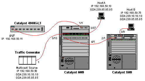
The 4908G-L3 creates a (*,G) and an (S,G) entry for the new group address:
4908g-l3# show ip mroute
IP Multicast Routing Table
Flags: D - Dense, S - Sparse, C - Connected, L - Local, P - Pruned
       R - RP-bit set, F - Register flag, T - SPT-bit set, J - Join SPT
       X - Proxy Join Timer Running
       Outgoing Interface Flags: H - Hardware switched
Timers: Uptime/Expires
Interface state: Interface, Next-Hop or VCD, State/Mode

(*, 239.85.85.85), 00:00:37/00:02:59, RP 0.0.0.0, flags: DP
  Incoming interface: Null, RPF nbr 0.0.0.0
  Outgoing interface list: Null

(192.168.50.50, 239.85.85.85), 00:00:38/00:02:21, flags: PT
  Incoming interface: GigabitEthernet1.50, RPF nbr 0.0.0.0
  Outgoing interface list: Null

(*, 239.10.10.10), 00:13:44/00:02:59, RP 0.0.0.0, flags: DJC
  Incoming interface: Null, RPF nbr 0.0.0.0
  Outgoing interface list:
    GigabitEthernet1.50, Forward/Dense, 00:13:44/00:00:00

(192.168.50.50, 239.10.10.10), 00:00:38/00:02:21, flags: PCT
  Incoming interface: GigabitEthernet1.50, RPF nbr 0.0.0.0
  Outgoing interface list: Null

4908g-l3#
The 6009 creates a source-only forwarding entry for the new multicast MAC address that includes only the multicast router port (1/1) in VLAN 50:
t6009> (enable) show multicast group
VLAN  Dest MAC/Route Des    [CoS]  Destination Ports or VCs / [Protocol Type]
----  ------------------    -----  -------------------------------------------
50    01-00-5e-00-01-28             1/1
50    01-00-5e-0a-0a-0a             1/1,4/1
50    01-00-5e-55-55-55             1/1

Total Number of Entries = 3
Cat6009> (enable)
Now, Host A and Host B join the 239.85.85.85 group using the ip igmp join-group 239.85.85.85 interface configuration command.
The following output is from the Catalyst 6009 switch after Host A and Host B have joined the multicast group 239.85.85.85:
Cat6009> (enable) show multicast group
VLAN  Dest MAC/Route Des    [CoS]  Destination Ports or VCs / [Protocol Type]
----  ------------------    -----  -------------------------------------------
50    01-00-5e-00-01-28             1/1
50    01-00-5e-0a-0a-0a             1/1,4/1
50    01-00-5e-55-55-55             1/1,3/37,4/1

Total Number of Entries = 3
Cat6009> (enable)
Notice that the switch has added ports 3/37 (Host A) and 4/1 (the trunk to the 5509) in the entry for 01-00-5e-55-55-55 in VLAN 50.
The following output is from the Catalyst 5509 switch after Host A and Host B have joined the multicast group 239.85.85.85:
Cat5509> (enable) show multicast group
VLAN  Dest MAC/Route Des    [CoS]  Destination Ports or VCs / [Protocol Type]
----  ------------------    -----  -------------------------------------------
50    01-00-5e-0a-0a-0a             2/1,3/9
50    01-00-5e-55-55-55             2/1,3/9

Total Number of Entries = 2
Cat5509> (enable)
Notice that the switch has added an entry for 01-00-5e-55-55-55 in VLAN 50 and has added port 2/1 (the trunk to the 6009) and port 3/9 (Host B).
Configuration Using the IGMP Snooping Querier Feature
Previously, when the source and receivers were on the same VLAN and you wanted to ensure that the multicast traffic only gets sent to the receivers that are interested in the traffic, PIM needed to be enabled on the router interface corresponding to the VLAN and CGMP or IGMP snooping needed to be used.
As of CatOS version 7.1 on the Catalyst 6500/6000 series switches, there is a new feature called IGMP snooping querier. This feature enables IGMP snooping within a VLAN where PIM and IGMP is not configured because the multicast traffic does not need to be sent to any other VLAN. If there is no multicast router on the VLAN where you want the multicast traffic to go between source and receivers, you need to enable the IGMP snooping querier feature in order to make this work correctly.
When the IGMP querier feature is configured for a certain VLAN, the switch sends out IGMP general queries every 125 seconds and listens for other general queries from other switches. When there are several switches that have IGMP querier enabled for a certain VLAN, there is an election process to determine which of the switches will continue to act as the querier. The other switches that have lost the election, start a timer and if no queries are being heard during that time, there will be a re-election for a new querier.
Two Catalyst 6000 switches, one running CatOS Software version 8.1(3), and the other running CatOS software version 7.6(2a), are used to test this feature. The topology is shown below.
Figure 5: IGMP Querier Example 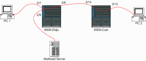
The source and the receivers are all on VLAN 9. IGMP querier is enabled on both switches.
Didju (enable) set igmp querier enable 9
IGMP querier is enabled for VLAN(s) 9

Cust (enable) set igmp querier enable 9
IGMP querier is enabled for VLAN(s) 9
This is already enough configuration to make this feature work, but there is still some fine tuning that can be done.
Cust (enable) set igmp querier 9 ?
  qi                         Query Interval for the vlan(s)
  oqi                        Other Querier Interval for the vlan(s)
The Query Interval, which by default is 125 seconds, specifies the frequency with which the switch that is elected querier sends IGMP general queries.
The Other Querier Interval, which by default is 300 seconds, specifies the amount of time that a switch in the non-querier state waits for a general query from the querier switch. If the general query is not received in the configured time interval from the elected querier switch, the candidate querier switch becomes a querier switch. This functionality is similar to a “dead timer.”
To check the current status of the IGMP Querier on both switches:
Cust (enable) show igmp querier information 9
VLAN Querier State         Query Tx Count QI (seconds) OQI (seconds)
---- --------------------- -------------- ------------ -------------
9    QUERIER               4              125          300
Cust (enable)

Didju (enable) show igmp querier information
VLAN Querier Address Querier State         Query Tx Count QI (sec) OQI (sec)
---- --------------- --------------------- -------------- -------- --------
9    0.0.0.0         NON-QUERIER           0              125      300
Didju (enable)
From the above outputs, you can see that the switch called "Cust" has been elected querier, that the query interval is 125 seconds and the “dead timer” on the non-querier is 300 seconds.
In this example, the multicast source sends traffic to the group 239.10.10.10, which corresponds on Layer 2 to the MAC address 01-00-5E-0A-0A-0A.
Now check the ports which are added by IGMP to the multicast group.
Didju (enable) show multicast group
VLAN  Dest MAC/Route Des    [CoS]  Destination Ports or VCs / [Protocol Type]
----  ------------------    -----  -------------------------------------------
9     01-00-5e-0a-0a-0a             2/7-8

Total Number of Entries = 1
Didju (enable)

!--- Port 2/7 is the port connected to PC 1 and !--- Port 2/8 connects to Cust, the second 6000.
On Cust, you see the following:
Cust (enable) show multicast group
VLAN  Dest MAC/Route Des    [CoS]  Destination Ports or VCs / [Protocol Type]
----  ------------------    -----  -------------------------------------------
9     01-00-5e-0a-0a-0a             3/13-14

Total Number of Entries = 1
Cust (enable)

!--- Port 3/13 connects to PC 2 and 3/14 to Didju.
In the show multicast router command, you get an indication where the router doing the IGMP querying is located.
On Cust, the switch elected as IGMP querier shows no output, as seen below.
Cust (enable) show multicast router
Port           Vlan
-------------- ----------------

Total Number of Entries = 0
'*' - Configured
'+' - RGMP-capable
'#' - Channeled Port
'$' - IGMP-V3 Router
'@' - IGMP-Querier Router
Cust (enable)
On the second switch Didju, the following can be seen:
Didju (enable) show multicast router
Port           Vlan
-------------- ----------------
 2/7              @  9

Total Number of Entries = 1
'*' - Configured
'+' - RGMP-capable
'#' - Channeled Port
'$' - IGMP-V3 Router
'@' - IGMP-Querier Router
Didju (enable)
Here, the multicast router port is port 2/7 (the port that connects to Cust) and via the '@' sign, it tells that the IGMP Querier feature is being used.
Related Information
Contact Cisco
- Open a Support Case

- (Requires a Cisco Service Contract)
 Feedback