Introduction
This document describes the Virtual PortChannel (vPC) Role election process on Nexus Series Switches.
Prerequisites
Requirements
Cisco recommends that you have knowledge of these topics:
- vPC on Nexus Series Switches
- Spanning Tree Protocol (STP)
Components Used
The information in this document is based on the Nexus 9000 Series Switch platform.
The information in this document was created from the devices in a specific lab environment. All of the devices used in this document started with a cleared (default) configuration. If your network is live, ensure that you understand the potential impact of any command.
Virtual PortChannel Technology
Virtual PortChannels (vPCs) allow links that are physically connected to two different Cisco switches to appear as a single PortChannel to a third device. The third device can be a switch, a server, or any other networking device that supports IEEE 802.3ad PortChannels. vPC also allows the creation of Layer 2 PortChannels that span two switches. At this time, vPC is implemented on Cisco Nexus 9000, 7000, 5000, and 3000 Series platforms (with or without Cisco Nexus 2000 Series Fabric Extenders).
Note: Cisco NX-OS Software vPCs and Cisco Catalyst Virtual Switching Systems (VSS) are of similar technologies. For Cisco EtherChannel technology, the term Multi-chassis EtherChannel (MCEC) interchangeably refers to either technology.
vPC Role
Although both vPC switches appear as a single switch to a downstream device, among themselves, two vPC switches have clearly defined vPC roles: vPC Primary and vPC Secondary.
vPC roles are non-preemptive, which means a device can be configured as vPC primary, but operate as vPC secondary peer device. This can happen in this scenario:
- When the original primary device fails, the secondary vPC device becomes the new primary device.
- When the system recovers itself, the previously primary device is now the secondary device and vice versa.
vPC role defines which of the two vPC peer devices processes Bridge Protocol Data Units (BPDUs) and responds to Address Resolution Protocol (ARP) requests. vPC role also defines a set of actions to be taken by vPC primary and vPC secondary in response to vPC peer-link down situation.
vPC Role Priority
You can also use role priority in vPC domain mode command to influence vPC Election process. The range of values is from 1 to 65636, and the default value is 32667. A lower value means that this switch has a better chance to be the primary vPC.
When you change the priority of the vPC peer devices, it can cause the interfaces in your network to go up and down. If you want to configure the role priority again to make one vPC device the primary device, configure the role priority on both the primary vPC device with a lower priority value and the secondary vPC device with the higher value. Then, shut down the vPC peer link on both devices and enter the shutdown command, and finally re-enable the port-channel on both devices and enter the no shutdown command.
Hitless vPC Role Change
The vPC hitless role change feature provides a framework to switch vPC roles between vPC peers without an impact on traffic flows. The vPC role swapping is done based on the role priority value of the device under the vPC domain. A vPC peer device with lower role priority is selected as the primary vPC device when the vpc role preempt command is executed.
Please see Use Case Scenario for Hitless vPC Role Change for more details.
vPC Systems Behavior When a vPC Peer-Link Goes Down
When vPC peer-link fails down and vPC peer-keepalive link is still up, the vPC secondary peer device performs these operations:
- Suspends its vPC member ports.
- Shuts down the SVI associated with the vPC VLAN.
This protective behavior from vPC redirects all south-to-north traffic to the vPC primary device.

Note: When vPC peer-link is down, both vPC peer devices cannot synchronize with each other anymore, so the designed protection mechanism leads to the isolation of one of the peer devices (in occurrence, the secondary peer device) from the data path.
vPC Primary Sticky Bit
vPC Primary Sticky bit is a Programmed Protection Mechanism introduced to avoid unnecessary role change (which would potentially cause disruption on the network) when the Primary Switch gets reloaded unexpectedly. vPC Primary Sticky Bit allows the alive switch sticks to its PRIMARY role when a dead switch comes back alive or when an isolated switch is integrated back into the VPC domain.
Toggling vPC Primary Sticky Bit:
1. vPC Primary Sticky Bit value is set to TRUE in this scenario:
- The current vPC Primary reboots and the vPC-enabled switch changes its role from vPC Secondary to vPC Operational Primary. The sticky bit is not set if the role changes from vPC Operational Secondary to vPC Primary.
- A vPC-enabled switch changes its role from None establish to vPC Primary when reload restore timer (240 sec by default) expires.
2. vPC Primary Sticky Bit value is set to FALSE in these scenarios:
- A vPC-enabled switch is rebooted (Sticky Bit is set to FALSE by default).
- vPC role priority is changed or re-entered.
vPC Sticky Primary bit is reported under vPC Manager software component structure, and can be checked with this NX-OS exec mode command.
Campus_N7K2-VPC# show system internal vpcm info global | include ignore-case sticky
        Sticky Primary: TRUE
Campus_N7K2-VPC#
vPC Delay Restore
After a vPC peer device reloads and comes back up, the routing protocol needs time to reconverge. The recovering vPCs leg can black hole routed traffic from access to aggregation/core until uplink Layer 3 connectivity is re-established.
vPC Delay Restore feature delays vPCs leg bring-up on the vPC peer device that recovers. vPC Delay Restore allows for Layer 3 routing protocols to converge before they allow any traffic on vPC leg. This results in a more graceful restoration and zero packet loss during the recovery phase (traffic still gets diverted on the alive vPC peer device). This feature is enabled by default with a vPC restoration default timer of 30 seconds. The timer can be tuned to a specific Layer 3 convergence baseline from 1 to 3600 seconds.
vPC Delay Restore Interface Vlan
To delay the VLAN interfaces on the restored vPC peer device from coming up, use the interfaces-vlan option of the delay restore command. This feature is enabled by default with a vPC restoration default timer of 10 seconds.
vPC Delay Restore while using Scaled SVI Setup of 4000 SVI
A new command delay restore interface-VLAN batch <1-4094> is introduced to configure the pacer to bring up the VLAN or bridge-domain interfaces in a batch of 200 SVIs at a time. The vPC delay restore timer command delay restore <Timeout value> can be configured to a value greater than the sum of all batch timers configured. This is done so that the VPC leg is brought up only after all the SVIs have completely come up to avoid any blackhole of traffic.
Example: 4000 Vlans, 200 batch, 15 sec delay
delay restore > (4000/200)x 15
vPC Election Process
In a vPC system, one vPC peer device is defined as vPC primary and one is defined as vPC secondary, based on these parameters and in this order
- vPC Primary sticky-bit set to 0 or 1.
- User-defined vPC role priority (Cisco NX-OS software uses the lowest numeric value to elect the primary device).
- System mac address value (Cisco NX-OS software uses the lowest MAC address to elect the primary device).
This flowchart (Image 1) summarizes steps that both vPC peer devices go through during vPC primary switch election process.
- The first checked parameter between two devices during vPC primary election process is vPC Primary Sticky Bit. If vPC peer device wins this comparison, it becomes vPC primary regardless of the configured vPC role priority value or system MAC addresses both peers have.
- If both vPC peer switches have the same Sticky Bit value, the election process proceeds to the next step to compare the user-defined vPC role priority.
- If both vPC roles are configured to the same value, the election process proceeds to compare the system MAC addresses.
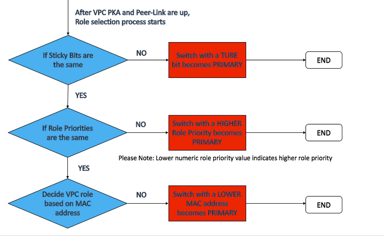
Image 1
As shown in the image, when the vPC switch has vPC Primary Sticky Bit set to 1 (TRUE condition) and its peer with the Sticky Bit set to 0 (FALSE condition), the TRUE side wins the election and assumes the role of vPC Primary.
| vPC Peer 1 Sticky Bit set to 1 |
vPC Peer 2 Sticky Bit set to 1 |
vPC Primary |
| False (0) |
False (0) |
Tie |
| True (1) |
False (0) |
vPC Peer 1 |
| False (0) |
True (1) |
vPC Peer 2 |
| True (1) |
True (1) |
Tie |
vPC Recovery Scenario
It is important to understand the vPC Election process and it cannot be underestimated, especially in vPC recovery scenarios.
Image 2 shows a typical VPC setup, Nexus-01 is the VPC Primary and Nexus-02 is the VPC Secondary. Both of them have their Sticky Bits re-set to FALSE by default.
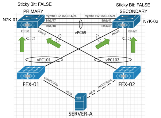
Image 2
As shown in this image, Nexus-01 now has a power outage and has been isolated from the network. Nexus-02 promoted itself to vPC Primary and set vPC Sticky Bit to TRUE.
And Nexus-02 now becomes Operational Primary, and the sticky bit is now set to TRUE.
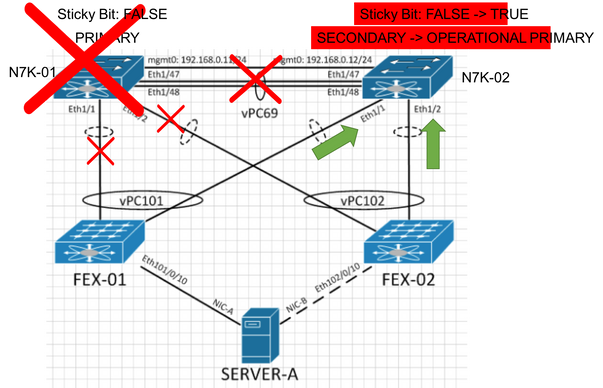
Image 3
As shown in this image, when Nexus-01 comes back online after the power outage has been restored, Nexus-02 retains the Operational PRIMARY role regardless of its role priority (because it has a TRUE sticky bit) and Nexus-01 takes the SECONDARY role when it comes online. Only Nexus-01 begins the VPC initialization process whereas Nexus-02 remains PRIMARY and forwards traffic as usual. Therefore, no network outage is seen.
There are two timers associated with the vPC initialization process on Nexus-01, which is now the vPC operational Secondary device:
- delay restore SVI (10 seconds by default)
- delay restore (30 seconds by default)
As a result, you can expect a 40-second recovery time on Nexus-01 after Nexus-01 is re-introduced back into the network as a vPC Secondary device. However, since Nexus-02 takes the Primary role, all traffic now is passing through Nexus-01 as mentioned above, no network outage is seen.
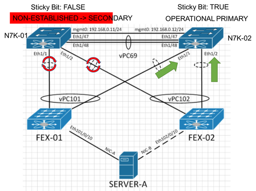
Image 4
Example of Network Outage Relevant to Wrongly Set Sticky Bit
The network outage is caused by an INCORRECTLY set sticky bit when an isolated switch (Nexus-02) is introduced back to the VPC domain
However, a network outage can occur after an isolated switch is introduced back to the VPC domain if the sticky bits are not set correctly on both Nexus switches. Before an isolated switch is introduced back to the VPC domain, its sticky bit must be set to FALSE. (For procedures to replace an N7K chassis, see Nexus 7000 Chassis Replacement Procedure.)
As shown in Image 5, Nexus-01 is configured with a higher VPC role priority than Nexus-02, and Nexus-02 has its Sticky Bit set to TRUE. Link E1/1 and E1/2 of Nexus-01 are in forwarding state whereas E1/1 and E1/2 in a shutdown state.
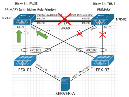
Image 5
When the PKA and Peer Link are restored, Nexus-02 takes the PRIMARY role regardless of its role priority (because it has a TRUE sticky bit) and forces Nexus-01 to become SECONDARY and the VPC initialization process begins on Nexus-01. Therefore, link E1/1 and E1/2 of Nexus-01 is suspended by VPC and comes online after the relay restore timers (40 seconds by default) expire. In this case,a 40-second network outage is seen after the PKA and Peer Link are restored, as shown in image 6.
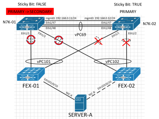
Image 6
Note: When a Nexus is reintroduced to the vPC domain, you must ensure that there is no vPC role change in the active vPC device. To avoid a vPC role change when the sticky bits of both switches are set to the same value, the active vPC device has to have a higher role priority for it to retain its PRIMARY role. Refer to Image 1 in this document for more information on VPC role election process.


 Feedback