PTP and SyncE basics with Cisco IOS XR Configuration
Available Languages
Download Options
Bias-Free Language
The documentation set for this product strives to use bias-free language. For the purposes of this documentation set, bias-free is defined as language that does not imply discrimination based on age, disability, gender, racial identity, ethnic identity, sexual orientation, socioeconomic status, and intersectionality. Exceptions may be present in the documentation due to language that is hardcoded in the user interfaces of the product software, language used based on RFP documentation, or language that is used by a referenced third-party product. Learn more about how Cisco is using Inclusive Language.
Contents
Introduction
This document describes the working of Precision Time Protocol (PTP) and Synchronous Ethernet (SyncE) with sample configurations, examples, and troubleshooting commands for Cisco IOS® XR devices in 8275.1 and 8275.2 telecom profiles.
Background Information
A clock for us is a wall clock or a wristwatch, but for networking devices, it is a periodic signal of alternate 0’s and 1’s which is used to sample the data bits. Just like a seconds hand in the clock has an angular movement to represent a second, a pair of 0 and 1 represents T (time period [T=1/frequency]). In order to generate this clock, network devices use a crystal oscillator which has a ±100 ppm error (parts per million. for example, a clock with the frequency of 250 MHz and 100 ppm will have a frequency range of 249.975 MHz to 250.025 MHz.) in generating the clock signal. So, ideally, the clock is not completely periodic but is sufficient for the requirement of sampling the data signals out of the interfaces.

Telecom networks (3G/4G/5G) use a very high quality (stratum) clock and all the base stations (NodeB’s/eNodeB’s and so on) should get synchronized to this clock with as little error/delay (approximately 1µs) as possible.
- One option is to install a GPS at all the base stations, which is quite costly and less secure as GPS works on satellite systems.
- The second option is to use the existing Networking Equipment (NE) to transfer the clock information along with the data signal. This option is very cost-effective as the data is already being transferred by NEs and the use of NEs for clock signal transfer will make it cheaper and more secure. However, clock quality might not be as good as compared to the earlier GPS option and will vary on the profile/protocol used in NEs as well as the congestion in the network.
Importance of Phase/Frequency Synchronization
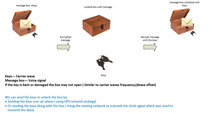
A message signal (for example, voice signal) modulated with a high frequency (carrier signal) wave at the transmitter end must be demodulated at the receiver end with the same carrier signal used at the transmitter end. If any change/offset in frequency or phase of the carrier wave happens at the receiver, the message signal will be corrupted. However, a little offset is always expected between the Rx carrier wave and the Tx carrier wave.

An analogy is to use a safe box to send a message and lock it with a key. If anyone wants to read the message in the safe box, the same key must be used to unlock the box at the receiver end. If the replica key has any distortions/disfigurement, the message cannot be read.
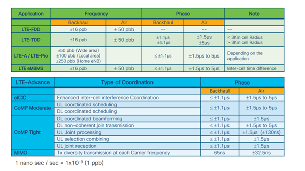
Acceptable offsets for various telecom services are:
Network Clock Synchronization
Synchronization is the alignment of clocks to the same time/phase and frequency.
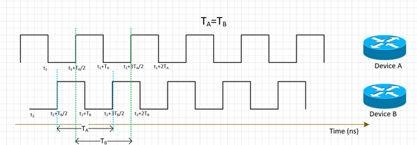
Synchronization for clocking can be categorized into frequency synchronization (achieving = / = where = also called as same rate), phase synchronization (at same time), and time synchronization (time of day).
Frequency Synchronization
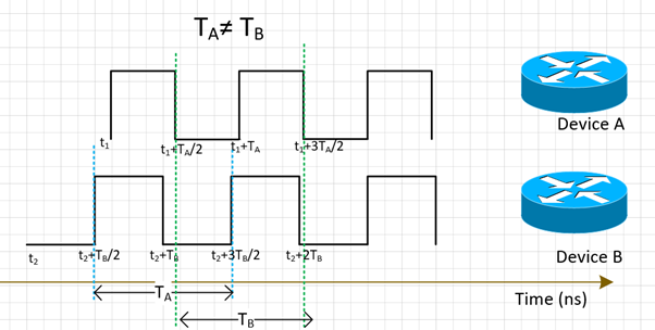
All the NEs shall match their clock’s frequency to a source clock (derived from a MasterClock).
Frequency synchronization for NE can be achieved with SyncE or PTPv2 which will be discussed further in this section.
SyncE works on deriving the frequency from data packets received on the interface (works on the physical layer) along with ESMC packets received (one packet per second approximately) on the interface which describes the quality of the clock. So, it does not add any control packets and is not affected by traffic congestion which is the best aspect of SyncE.
PTP runs on packets, so there will be a control packets flow and the packets will get affected by congestion which adds to the delay.
Phase Synchronization
Phase synchronization is about the alignment of these clock signals. We can see that the above frequency synchronized signals are not yet aligned, so they have a phase offset.
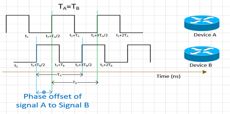
PTPv2 is used to carry the phase information across the network.
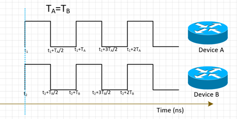
Time Synchronization
Time synchronization, also called Time of day, simply has the same time in all the NEs. That is, t1=t2.
NTP and PTP are used to transfer time information in the network. While NTP provides millisecond accuracy, PTP can provide up to sub-microsecond accuracy.
Time synchronization and phase synchronization are often used synonymously in networking as PTP used to phase synchronize will achieve time synchronization.
NTP will not be part of our discussion now.
SyncE
Basic Principle of SyncE
SyncE works on the basic principle of extracting the clock frequency from the data received on a port.
A simple example is illustrated here. The data signal is processed with the local oscillator and the output data is sent out of the Tx port. You can observe that the clock frequency is present in the Data signal transmitted on the port. SyncE works on the principle of reverse processing the signal received on the Rx port and getting the frequency information of the transmitted clock.
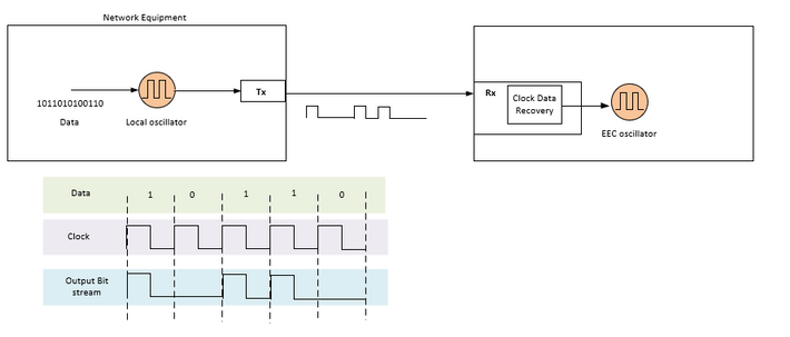
SyncE is a recommendation from ITU-T on how to deliver a frequency in a network. According to the recommendation, the frequency will be recovered from the bitstream in the physical layer as pointed out earlier. The clock that will be distributed in the chain is called the primary reference clock (PRC) and all clocks in the network shall be traceable to that clock. To get a traceable clock all nodes in a chain between the MasterClock and the end device need to be implemented with a synchronous Ethernet Equipment Clock (EEC) according to the SyncE recommendations. The performance of the recovered clock will not depend on the network load since it does not synchronize with any specific packet.
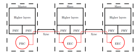
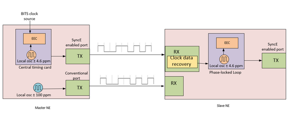
The MasterClock NE takes external input timing references that come from the network clock (SSU or BITS). These references are then used as input to the EEC clock, typically located on the central timing card of the NE. The EEC output timing reference is then used to sample data and send out the traffic on the SyncE enable Tx port.
At the SlaveClock NE, the clock is recovered within the transceiver clock data recovery (CDR). In some cases where the RX clock is not available at the transceiver, the use of an external CDR might be required to recover the clock. The clock is then sent through the backplane to reach the SlaveClock’s central timing card. This timing reference then becomes a reference to the EEC (also known as a line-timing reference). As shown in the SlaveClock NE, an EEC can accept line and external references, as well as the input of a ±4.6 ppm local oscillator (used in situations where there are no line or external references available). From this point on, the SlaveClock NE then becomes the MasterClock NE for the next downstream NE, and synchronization is transported on a node-to-node basis, where each node participates in recovery and distribution.
Ethernet Synchronization Messaging Channel
The Ethernet Synchronization Messaging Channel (ESMC) is an ITU-T defined Ethernet slow protocol (that is., the messages are sent to the multicast Ethernet destination address 01-80-C2-00-00-02 and use Ether Type 88-09) to prevent the messages from leaking from a synchronized link to another link.
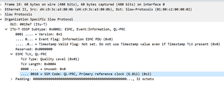
It carries the Synchronization Status Message (SSM) information which is the quality level (QL) of the transmitting clock. For example: If the upstream device is in sync with a PRC clock, then the QL value received is QL-PRC and the corresponding SSM value is 0010.
ESMC information PDUs are sent periodically at a rate of one PDU per second. Lack of reception of an ESMC PDU within a five-second period results in the SSF=true (QL=QL-FAILED). The default (initial) value for the QL is DNU (SSM=1111) and must only change when a valid QL TLV is received.
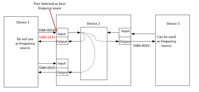
We need to note that if a device is dual-homed and the source of signal for both upstream devices is PRC, then the QL received on the device from both links is QL-PRC. Hence, we need to prioritize the links accordingly to choose the right upstream device with regard to hops, links, and so on.
The MasterClock-SlaveClock synchronization over several NEs with multiple possible synchronization inputs for protection of synchronization could lead to timing loops between NEs. In order to avoid timing loops, an NE should insert an SSM value of DNU in the direction of the NE, which is used as the actual synchronization source for the NE clock.
SyncE with LAG
SyncE works on the Physical layer and the ESMC packets are also carried by Ethernet slow protocol. LAG is another function that utilizes slow protocols and LAG operates above ESMC. Processing of ESMC messages is therefore required on each synchronous Ethernet-enabled link in the LAG group.
It is also important to note that the use of parallel links, such as the case with LAG, needs to be carefully considered due to the potential for the creation of timing loops.
Ideally, it is sufficient to run it on the single-member link of the bundle but otherwise, It is left to the operators to configure several synchronous Ethernet-enabled ports.
PTPv2/1588v2
IEEE 1588 is defined by the Institute of Electrical and Electronics Engineers (IEEE) in 2002 as Precision Clock Synchronization Protocol (PTP) for networked measurement and control systems. It is called the Precision Time Protocol (PTP) for short.
IEEE 1588v1 applies to industrial automation and tests and measurements fields. With the development of IP networks and the popularization of 3G networks, the demand for time synchronization on telecommunications networks has increased. To satisfy this need, IEEE drafted IEEE 1588v2 based on IEEE 1588v1 in June 2006, revised IEEE 1588v2 in 2007, and released IEEE 1588v2 at the end of 2008.
1588v2 is a time synchronization protocol that allows for highly accurate time synchronization between devices. It is also used to implement frequency synchronization between devices.
This packet-based synchronisation mechanism combines frequency and phase synchronisation at sub-microsecond levels, with ToD distribution capabilities via the efficient mechanism of packet exchanges
The major weakness of PTP is also due to its packet nature, as the synchronisation packets used by PTP are forwarded in the network between MasterClock and hosts, which are subject to all network events such as frame delay (latency), frame delay variation (packet jitter) and frame loss. Even with the best practice of applying high priority to synchronisation flows, these synchronisation packets will still experience congestion and possible routing and forwarding issues such as out-of-sequence and route flaps.
Basic Working Principle of PTP
We send the time (hh:mm:ss) in a packet and we use packet flow round trip time to find the delay in transmission of a packet and correct the clock time by adjusting with the half of round trip delay.
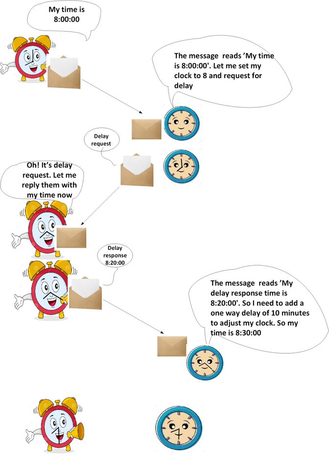
Working of PTP
PTP uses a hierarchical MasterClock-SlaveClock architecture for clock distribution.
It specifies how the real-time clocks in the system synchronize with each other. These clocks are organized into a MasterClock−SlaveClock synchronization hierarchy with the clock at the top of the hierarchy the MasterClock determining the reference time for the entire system. The synchronization is achieved by exchanging PTP timing messages, with the SlaveClocks using the timing information to adjust their clocks to the time of their MasterClock in the hierarchy.
PTP was designed assuming a multicast communication model. PTP also supports a unicast communication model as long as the behaviour of the protocol is preserved. PTP assumes that Announce messages are periodically sent by one port and delivered to all other ports of the ordinary or boundary clocks within a communication path. If the communication path consists of more than two ports, the assumption is that Announce messages are either sent in multicast or the Announce information is replicated to all ports in the communication path using unicast messages. PTP ports discover other ports within a communication path through the receipt of multicast Announce messages.
The protocol executes within a logical scope called a domain. All PTP messages, data sets, state machines, and all other PTP entities are always associated with a particular domain id
The protocol defines the event and general PTP messages. Event messages are timed messages i.e., an accurate timestamp (time recorded on the device at entry/exit point but it is not necessary that the message carries the time t) is generated at both transmission and receipt. General messages do not require accurate timestamps.
PTP Domains
A domain consists of a logical grouping of clocks communicating with each other using the PTP protocol.
PTP domains are used to partition a network within an administrative entity. The PTP messages and data sets are associated with a domain and therefore, the PTP protocol is independent for different domains.
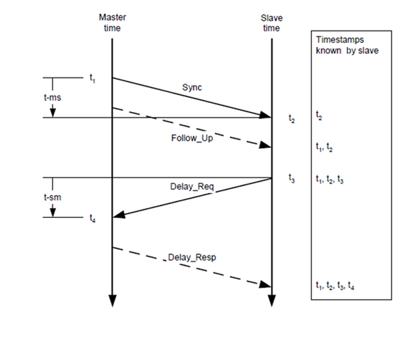
Message Exchange Pattern
- The MasterClock sends a Sync message to the SlaveClock and notes the time at which it was sent.
- The SlaveClock receives the Sync message and notes the time of reception.
- The MasterClock conveys to the SlaveClock the timestamp by:
- Embedding the timestamp in the Sync message. This requires some sort of hardware processing for highest accuracy and precision.
- Embedding the timestamp in a Follow_Up message.
- The SlaveClock sends a Delay_Req message to the MasterClock and notes the time at which it was sent.
- The MasterClock receives the Delay_Req message and notes the time of reception.
- The MasterClock conveys to the SlaveClock the timestamp by embedding it in a Delay_Resp message.
PTP time accuracy is degraded by asymmetry in the paths taken by event messages. Specifically, the time offset error is 1/2 of the asymmetry.
Asymmetry is not detectable by PTP. However, if known, PTP corrects for asymmetry. Asymmetry can be introduced in the physical layer, e.g., via transmission media asymmetry, by bridges and routers, and in large systems by the forward and reverse paths traversed by event messages taking different routes through the network. Systems should be configured, and components selected to minimize these effects guided by the required timing accuracy. In single subnet systems with distances of a few meters, asymmetry is not usually a concern for time accuracies above a few 10s of ns.
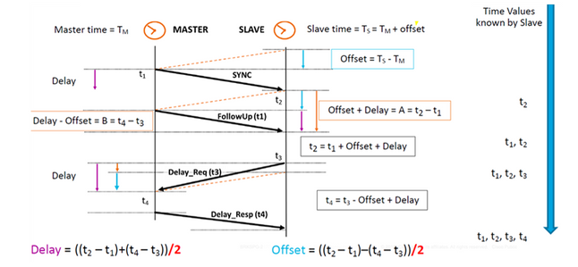
Various Packet Types
The set of event messages consists of:
- Sync - Used for synchronization of time between MasterClock and SlaveClock. In Two-step, Sync messages do not carry time but the time will be time-stamped at the MasterClock and will be carried in Follow_Up message. In One-step, the Sync message will carry time. Old devices/hardware couldn’t support measuring and carrying the exit time point when a message was delivered out a port, so two-step was because of hardware limitation. Nowadays, hardware can record the exit time point and send it inside the Sync message. One-step is backwards compatible with two-step.
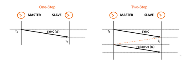
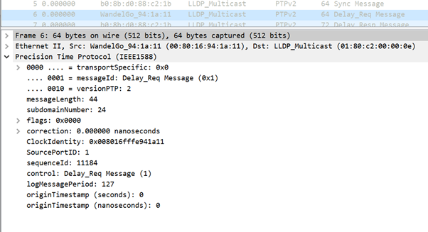
- Delay_Req - A Delay_Req message is a request from the receiving/SlaveClock node to return the time at which the Delay_Req message was received, using a Delay_Resp message. It will be used to calculate the transit time between SlaveClock and MasterClock. This message is time-stamped at the SlaveClock.
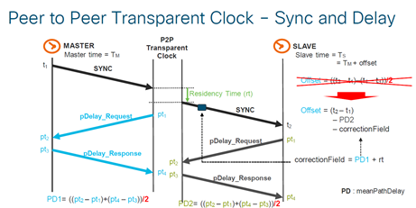
- Pdelay_Req - A Pdelay_Req message is transmitted by a PTP port to another PTP port as part of measuring port-to-port propagation time to determine the delay on the link between them. It is used by P2P transparent clock to calculate the per-hop link delay.
- Pdelay_Resp - A Pdelay_Resp message is transmitted by a PTP port in response to the receipt of a Pdelay_Req message.
The set of general messages consists of:
- Announce - This message is used by the Best MasterClock Algorithm (BMCA) to generate MasterClock-SlaveClock topology. It is used to elect the best MasterClock and keep it in place.
- Follow_Up - This message type is used in the two-step mode. It carries the time. (Sync exit time on MasterClock node) in its message.
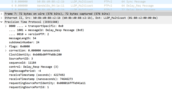
- Delay_Resp - It is used to calculate the transit time from MasterClock to SlaveClock. It carries the time (exit time of Delay_Resp message) in the message.
- Pdelay_Resp_Follow_Up - This is similar to the Follow_Up message but it is generated by a P2P transparent clock.
- Management: Not part of our discussion.
- Signaling - For communication between clocks for all other purposes. For example, signaling messages can be used for the negotiation of the rate of unicast messages between a MasterClock and its SlaveClocks.
The Sync, Delay_Req, Follow_Up, and Delay_Resp messages are used to generate and communicate the timing information needed to synchronize ordinary and boundary clocks using the delay request-response mechanism.
The Pdelay_Req, Pdelay_Resp, and Pdelay_Resp_Follow_Up messages are used to measure the link delay between two clock ports implementing the peer delay mechanism. The link delay is used to correct timing information in Sync and Follow_Up messages in systems composed of peer-to-peer transparent clocks.
Ordinary and boundary clocks that implement the peer delay mechanism can synchronize using the measured link delays and the information in the Sync and Follow_Up messages. The Announce message is used to establish the synchronization hierarchy. The management messages are used to query and update the PTP data sets maintained by clocks. These messages are also used to customize a PTP system and for initialization and fault management. Management messages are used between management nodes and clocks (will not be part of our discussion).
The signalling messages are used for communication between clocks for all other purposes. For example, signalling messages can be used for the negotiation of the rate of unicast messages between a MasterClock and its SlaveClocks.
PTP Device Types
There are five basic types of PTP devices, as follows:
- Ordinary clock - Can only be a Grand MasterClock (GM) or only a SlaveClock.
- Boundary clock - Can be both SlaveClock and GM
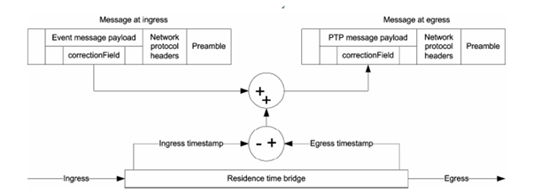
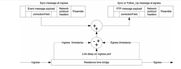
- End-to-end transparent clock - The end-to-end transparent clock forwards all messages just as a normal bridge, router, or repeater. However, for PTP event messages, the residence time bridge, shown in Figure below, measures the residence time (the time the message takes to traverse the transparent clock) of PTP event messages. These residence times are accumulated in a special field, the correction Field, of the PTP event message or the associated follow-up message. This correction is based on the difference in the timestamp generated when the event message enters and leaves the transparent clock.
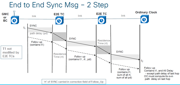
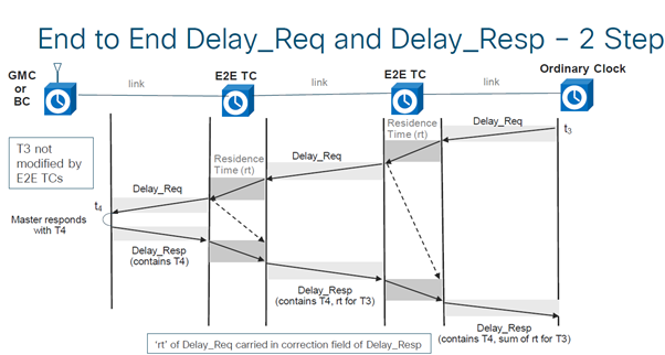
- Peer-to-peer transparent clock - Adds the residence time as well as link transit delay time to ptp messages by using the peer delay mechanism (generates its own delay-req-resp packets to calculate the peer link delay).
- Management node (not part of our discussion).
Establish the MasterClock−SlaveClock Hierarchy
Within a domain, each port of an ordinary and boundary clock executes an independent copy of the protocol state machine. For “state decision events,” each port examines the contents of all Announce messages received on the port. Using the best MasterClock algorithm, the Announce message contents and the contents of the data sets associated with the ordinary or boundary clock are analysed to determine the state of each port of the clock.
PTP State Machine
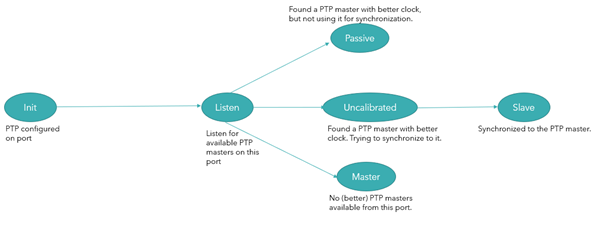
Each port of an ordinary and boundary clock maintains a separate copy of the PTP state machine. This state machine defines the allowed states of the port and the transition rules between states. The principal “state decision events” determining the MasterClock−SlaveClock hierarchy are the receipt of an Announce message and the end of an announce Interval (the interval between Announce messages). The port states that determine the MasterClock−SlaveClock hierarchy are as follows:
- INIT – Port is not yet ready to participate in PTP.
- LISTENING – First state when a port becomes ready to participate in PTP: port listens for PTP MasterClocks for a (configurable) period of time
- PRE-MasterClock – The port is about to go into MasterClock state.
- MasterClock – The port provides timestamps for any listening SlaveClock/boundary clocks.
- UNCALIBRATED – The port receives timestamps from a MasterClock, but the router's clock is not yet synchronized to that MasterClock
- SLAVE – The port receives timestamps from a MasterClock, and the router's clock is synchronized to that MasterClock
- PASSIVE – The port is aware of a better clock than the one it would advertise if it was in MasterClock state, but is not slaving off that clock
Best MasterClock Algorithm
The best MasterClock algorithm compares data describing two clocks to determine which data describes the better clock. This algorithm is used to determine which of the clocks described in several Announce messages received by a local clock port is the best clock. It is also used to determine whether a newly discovered clock—a foreign MasterClock—is better than the local clock itself. The data describing a foreign MasterClock is contained in the grandMasterClock fields of an Announce message.
The data set comparison algorithm is based on pair-wise comparisons of attributes with the following precedence:
- priority1 - A user-configurable designation that a clock belongs to an ordered set of clocks from which a MasterClock is selected
- clockClass - An attribute defining a clock’s TAI traceability
- clockAccuracy - An attribute defining the accuracy of a clock
- offsetScaledLogVariance - An attribute defining the stability of a clock
- priority2 - A user-configurable designation that provides finer-grained ordering among otherwise equivalent clocks
- clockIdentity - A tie-breaker based on unique identifiers
In addition to this precedence order, the “distance” measured by the number of boundary clocks between the local clock and the foreign MasterClock is used when two Announce messages reflect the same foreign MasterClock. The distance is indicated in the stepsRemoved field of Announce messages. This condition can occur in PTP systems with cyclic paths not removed by a protocol outside of PTP. The data set comparison algorithm unambiguously selects one of the two clocks as “better” or as “topologically better.”
Profiles
The purpose of a PTP profile is to allow organizations to specify specific selections of attribute values and optional features of PTP that, when using the same transport protocol, inter-work and achieve a performance that meets the requirements of a particular application.
A PTP profile should define:
- Best MasterClock algorithm options
- Configuration management options
- Path delay mechanisms (peer-delay or delay request-response)
- The range and default values of all PTP configurable attributes and data set members
- The transport mechanisms required, permitted or prohibited
- The node types required, permitted, or prohibited
- The options required, permitted, or prohibited
Various profiles defined for packet networking with PTP are as follows:
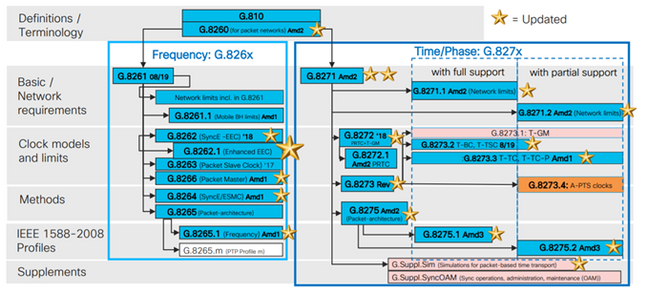
8265.x profiles are used for achieving frequency synchronization with PTP.
8275.x is used for time-of-day/Phase synchronization using PTP. NCS5xx/55xx presently supports 8265.1, 8275.1, 8275.2, and 8273.2.
8265.1 was earlier used for 3G/4G clock synchronization, whereas 8275.x is used now for 5G because of the rise in demand for accuracy with 5G networks.
8275.1
This annex contains the PTP telecom profile for phase/time distribution with full timing support from the network.
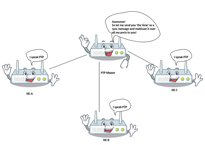
Synchronization Model:
G.8275.1 profile adopts the hop-by-hop synchronization model. Each network device in the path from Server to Client clock synchronizes its local clock to upstream devices and provides synchronization to downstream device
Node Types:
In this profile, the permitted node types are ordinary clocks, boundary clocks, and end-to-end transparent clocks.
In this profile, the prohibited node types are peer-to-peer transparent clocks.
Domains:
Domain ids from 24 to 43 can be used. The default domain id is 24
Clock Mode:
Both one-step and two-step clocks are permitted. A clock must be capable of receiving and handling messages transmitted from both one-step and two-step clocks. A clock is not required to support both one-step and two-step modes for transmitting messages.
Transport mechanisms required, permitted, or prohibited
In this profile, the allowed transport mechanisms are:
- IEEE 802.3/Ethernet and
- OTN
At least one of the two transport mechanisms must be supported. For transport over IEEE 802.3/Ethernet, both the non-forwardable multicast address, 01-80-C2-00-00-0E, and the forwardable multicast address, 01-1B-19-00-00-00, are required to be supported for compliance with this profile
Unicast/Multicast Messages:
All messages are sent multicast, using one of the two multicast addresses (01-80-C2-00-00-0E/01-1B-19-00-00-00). The unicast mode is not permitted in this version of the profile.
Best MasterClock Algorithm Options:
This profile uses the Alternate BMCA.
Following clock-parameters are compared (in order) from each available node to select the best MasterClock:
Table 1. Telcom Profile BMCA Hierarchy
|
Parameter |
Description |
|
Priority 1 |
NOT used in telecom profiles |
|
Clock-class |
Measure of clock traceability. Whether the MasterClock's frequency/time is traceable to a GNSS reference (A, B better than C) |
|
Clock-accuracy |
How accurate is the GM's clock output to primary reference? e.g: time accurate to within 25ns. |
|
Offset Scaled Log variance (OSLV) |
Measure of clock precision. How much the clock-output varies when not synchronized to another source. |
|
Priority 2 |
User defined priority on the MasterClock-node if all above parameters match |
|
Local port priority |
User defined per-port priority on DUT |
|
GM clock identity |
GrandMasterClock's clock ID used as a tie breaker |
|
Steps removed |
Shortest path chosen if grandMasterClock is reachable through multiple ports (A better than B) |
Path Delay Measurement Option (Delay Request/Delay Response):
The delay request/delay response mechanism is used in this profile. The peer-delay mechanism must not be used in this profile, the delay_req—response method must be used.
This PTP telecom profile defines an Alternate BMCA that allows using two main approaches to set up the topology of the phase/time synchronization network:
Automatic Topology Establishment:
When configuring the localPriority attributes defined in this Recommendation to their default value, the PTP topology is established automatically by the Alternate BMCA based on the Announce messages exchanged by the PTP clocks. A synchronization tree with the shortest paths to the T-GMs is built after this operation. In this mode, during failure events and topology reconfiguration, the Alternate BMCA will be run again and result in a new synchronization tree. This Alternate BMCA operation ensures that no timing loop will be created without requiring manual intervention or prior analysis of the network. The convergence time to the new PTP topology depends on the size of the network, and on the specific configuration of the PTP parameters.
Manual network planning: The use of the localPriority attributes defined in this Recommendation with different values than their default value allows building manually the synchronization network topology, in a similar way as Synchronous Digital Hierarchy (SDH) networks are typically operated based on the synchronization status message (SSM). This option allows full control of the actions during failure events and topology reconfiguration, based on the configured local priorities of the system. However, careful network planning is required prior to the deployment in order to avoid timing loops.
Considerations on the Use of Priority2:
The PTP attribute priority2 is configurable in this profile. In some special circumstances, the use of the priority2 attribute can simplify network management. This section describes two use cases; other possible cases are for further study.
- Case 1.
Operators can configure the PTP attribute priority2 to make all of the Telecom Boundary Clock (T-BCs) either traceable to one Telecom Grand MasterClock (T-GM) or traceable to two different T-GMs at the same time.

For example, in this image, if all other PTP attributes of the two T-GMs are the same, and the two T-GMs are configured with the same priority2 value, each T-BC will select the T-GM with the shortest path. If the two T-GMs are configured with different priority2 values, all of the T-BCs will synchronize to the T-GM with the smallest priority2 value.
- Case 2.
Operators can configure the PTP attribute priority2 to prevent the T-BCs of an upstream network from synchronizing with the T-BCs of a downstream network when the T-GM is in failure.
For example, in Figure, if all other PTP attributes of all of the T-BCs are the same, and the PTP attribute priority2 of all of T-BCs are configured with the same value, then when the T-GM is in failure, the T-BCs in the upstream network can synchronize with the T-BCs in the downstream network, depending on the clockIdentity values of all of the T-BCs. If the T-BCs in the upstream network are configured with a smaller priority2 value than the T-BCs in the downstream network then, when the T-GM is in failure, the T-BCs in the downstream network will synchronize to the T-BCs in the upstream network.

Operations over Link Aggregation:
When two devices embedding PTP clocks compliant with this profile are connected via a link aggregation (LAG), each physical link should be accessed directly to transmit PTP messages, bypassing the LAG. This method prevents potential asymmetries that may be present when the forward and reverse paths are delivered over different links belonging to the LAG.
Considerations on the Choice of the PTP Ethernet Multicast Destination Address:
This PTP profile supports both the non-forwardable multicast address 01-80-C2-00-00-0E and forwardable multicast address 01-1B-19-00-00-00 when the PTP mapping is used.
The Ethernet multicast address to be used depends on the operator policy; further considerations are provided hereafter.
Layer 2 bridging function associated with the PTP port of a T-BC or T-TC should not forward any frame with destination MAC address 01-1B-19-00-00-00; this could be done by properly provisioning this multicast address in the filtering database.
- Option 1 – Use of the non-forwardable multicast address 01-80-C2-00-00-0E.
Some network operators consider that the PTP messages must never be forwarded through PTP-unaware network equipment.
The use of the non-forwardable multicast address 01-80-C2-00-00-0E guarantees this property most of the time (exceptions exist for some older Ethernet equipment).
Therefore, in the case of network equipment misconfiguration (e.g., if the PTP functions are not enabled in PTP-aware network equipment), the use of this multicast address prevents incorrect distribution of synchronization, since the PTP messages will be blocked by the PTP-unaware network equipment.
- Option 2 – Use of the forwardable multicast address 01-1B-19-00-00-00.
Some network operators consider that using a forwardable multicast address is more flexible and that it is preferable to forward the PTP messages to keep the synchronization link running in case some equipment is misconfigured as non-PTP nodes, although there are potential risks of performance degradation. The network management system (NMS) will easily find the misconfiguration and will send alarms.
However, it is possible to block the PTP messages by properly provisioning this multicast address in the filtering database of each Ethernet equipment.
8275.2
This Recommendation defines another PTP profile to allow the distribution of phase and time with Partial Timing Support (PTS) from the network (i.e., no need for every device to run ptp in the network). The major difference between 8275.2 from 8275.1 is that it runs on IPv4 unicast and not all nodes in the network need to run PTP.

Transport Mechanisms:
In this profile, the required transport mechanism is UDP/IPv4.
Unicast Messages:
All messages are sent in unicast.
In this telecom profile, unicast negotiation is enabled per default.
The SlaveClock will initiate the session by following the unicast message negotiation procedure.
Domains:
Domain ids from 44 to 63 can be used. The default domain id is 44.
Best MasterClock Algorithm Options:
This profile uses the Alternate BMCA.
Properties lPath delay measurement option (delay request/delay response), Automatic topology establishment and Considerations on the use of priority2 are same as telecom profile 8275.1
Considerations of PTP over IP Transport in Ring Topologies:
When using PTP messaging over an IP transport layer, there are some aspects of the Layer 3 protocol that need to be considered. The PTP layer delivers messages into the IP layer with a destination IP address. The IP layer then ensures the message is delivered to the destination as long as there is some path through the IP transport network from the source node to the destination address. The IP layer includes dynamic routing protocols that can adapt the path through the network based on available links between the IP routers. It can happen that the path taken by the IP transport layer may not be the path 'expected' by the synchronization planner. Applying some restrictions in the IP transport layer to control suboptimal paths for PTP messages may be beneficial. This is likely to be the case in ring topologies.
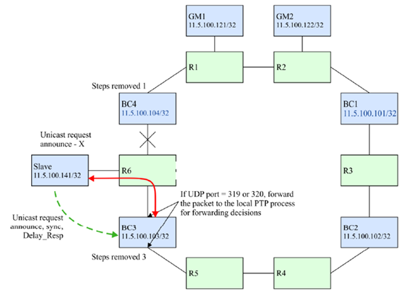
Taking the topology shown in Figure below as an example, the SlaveClock is configured to request unicast service from both BC3 and BC4. After receiving the Announce messages from both BC3 and BC4, the SlaveClock will run the BMCA and select BC4 as its parent clock based on the fact that the steps- the removed value of BC4 is 1, compared to a steps-removed value of 3 for BC3. The SlaveClock would then request Sync messages from BC4.
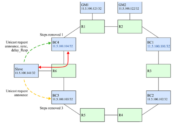
If the connection between BC4 and R6 breaks (see Figure below), then BC4 is not reached through the expected path. However, it can still be reached because routing protocols will retain the connection by routing the IP packets around the ring. BC4 is retained as the parent clock because it is still considered better by the BMCA.
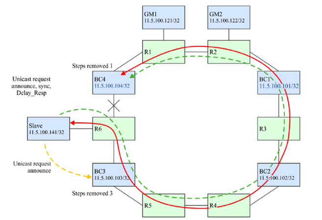
It is most likely that the desired operation is that the SlaveClock should switch to BC3 for better performance.
There are a few techniques that can be employed to ensure that in the failure scenario identified above, the SlaveClock will select BC3 as its parent clock. They are based on blocking the PTP IP messages from BC4 to the SlaveClock if those messages are transiting clockwise around the ring. The solution is based on blocking only the PTP messages and not the message of other protocols that might use the same IP addresses.
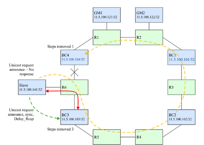
Option 1. Unique IP Addresses and Static Routes:
In some deployment models, it might be possible to allocate unique IP addresses for the use of PTP alone. This then allows the use of static routes to control the direction of the PTP flows between the nodes. BC4 would be configured such that the only path to use to reach 11.x.x.141 (SlaveClock) would be the link between BC4 and R6. In addition, R6 could be configured such that the only path to use to reach 11.y.y.104(BC4) would be the link between R6 and BC4. If the link between R6 and BC4 fails, then there is no route available to get the IP packets between 11.x.x.141 and 11.y.y.104 so the SlaveClock will not receive Announces from BC4 and the BMCA will select BC3 as the parent clock. Refer to this image.
Option 2. IP Filters
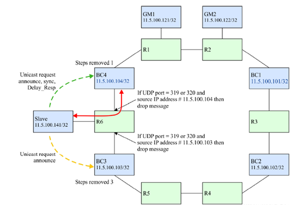
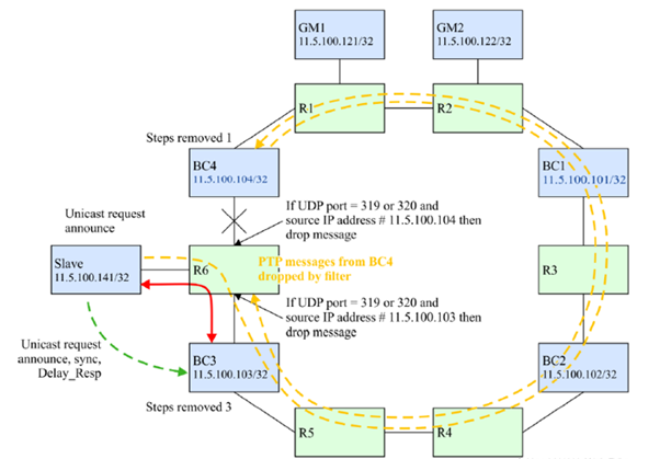
All routers support some level of IP filtering. Filters can be used to protect the control plane of the router from unwanted messages. They can be used in this case to control the acceptance of PTP messages on a subset of the routing interfaces.
In this case, R6 would be configured to protect the SlaveClock from PTP messages taking the wrong route. On the interface on R6 facing BC3, a filter could be applied to only allow messages to UDP port 319 or 320 if the source address matches that of the PTP process on BC3. Any messages sourced from BC4 that are received on that interface would be dropped. Refer to this image.
Option 3. BC Processing of All PTP Messages
A BC could terminate all PTP messages received into any of its ports for any domains used by the BC. Then the PTP messages could either be dropped or forwarded based on decisions within the PTP process itself. The choices might be to drop the message if the destination address of the PTP message was not an address owned by the BC or to deliver it to the forwarding engine to be sent onward to the destination. The latter case might be used if the PTP message is for a different domain than the BC. Also in the latter case, the network element containing the BC might also update the correction field of any forwarded event messages to compensate for the PTP message extraction and processing, i.e., support the transparent clock function for these messages. The message extraction from the IP plane can be accomplished if the router supports the policy-based routing of IP packets.
This example is shown in this image.
Option 4. Use of the Time to Live (TTL) Mechanism From IP Transport:
A PTP node might send PTP packets with the IP/Transport header carrying a TTL field set to the minimum number of routing hops required to reach the peer PTP port with which it has a PTP contract. In a typical PTP-unaware network having unaware routers between MasterClock and SlaveClock, if the number of PTP unaware routers is larger than the TTL value of the PTP message, the PTP message will be dropped by one of the PTP-unaware routers. This can be used to limit the number of IP hops traversed by PTP packets between adjacent routers and avoid communication through unwanted longer paths.
This behaviour might be per PTP port, or per PTP clock, and is implementation-specific. It is assumed that in such a ring topology, IP routing will take care of ensuring that a shorter path to the PTP MasterClock is considered as a better route than the longer path around the ring.
As an example, if a SlaveClock has a directly connected MasterClock that can also be reachable through a longer path, it can use the TTL value of 1 to ensure that PTP packets reach the MasterClock only through the directly connected path rather than the longer path around the ring.
Servo Algorithm
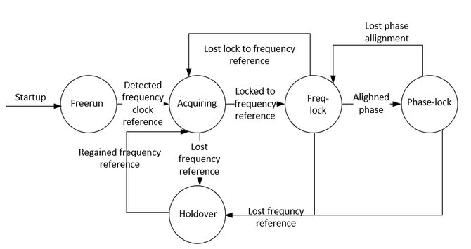
Description of the modes:
- Free-Run mode:
The PTP clock has never been synchronized to a time source and is not in the process of synchronizing to a time source.
- Acquiring mode:
The PTP clock is in process of synchronizing to a time source. The duration and functionality of this mode are implementation-specific. This mode is not required in implementation.
- Freq/Phase Locked mode:
Phase Lock-The PTP clock is phase synchronized to a time source and is within some internal acceptable accuracy.
Frequency Lock-The clock is frequency synchronized to a time source and is within some internal acceptable accuracy.
As it relates to the PTP port state defined in [IEEE 1588], a clock is in Locked mode if there is a PTP port in SLAVE state.
- Holdover mode:
The PTP clock is no longer synchronized to a time source and is using information obtained while it was previously synchronized or other information sources were still available, to maintain performance within the desired specification or are unable to maintain performance within the desired specification. The node may be relying solely on its own facilities for holdover or may use something like a frequency input from the network to achieve a holdover of time and/or phase.
Configuration Example for 8275.1/8275.2 on NCS 540 (Cisco IOS XR)
The router allows the ability to select separate sources for frequency and time-of-day (ToD). Frequency selection can be between any source of frequency available to the router, such as BITS, GPS, SyncE or IEEE 1588 PTP. The ToD selection is between the source selected for frequency and PTP, if available (ToD selection is from GPS, DTI or PTP). This is known as hybrid mode, where a physical frequency source (BITS or SyncE) is used to provide frequency synchronization, while PTP is used to provide ToD synchronization.
SyncE (for frequency transfer) and ptp (phase/time-of-day transfer) can be used together in the network while deploying 8275.1 to achieve better accuracies (called as hybrid mode and is the only supported mode for NCS as of version 7.3.x)
The local priority attribute is not transmitted in Announce messages. This attribute is used as a tie-breaker in the data set comparison algorithm, in the event that all other previous attributes of the data sets being compared are equal
8275.1:
|
Boundary Clock |
||
|
Configuration |
Explanation |
|
|
ptp |
ptp |
|
|
Clock |
||
|
domain 24 |
||
|
profile g.8275.1 clock-type T-BC |
Profile 8275.1 is being used with clock role to be T-BC telecom boundary clock |
|
|
! |
||
|
profile T-BC-MasterClock |
Define a role for ptp port. |
|
|
multicast target-address ethernet 01-80-C2-00-00-0E |
A non-forwardable multicast address is being used (Optional) |
|
|
transport ethernet |
ethernet transport is being used |
|
|
port state MasterClock-only |
port state to be used is MasterClock only |
|
|
sync frequency 16 |
Sync packets will be sent with a frequency of packets-per-second |
|
|
announce frequency 8 |
Announce packets will be sent with a frequency of packets-per-second |
|
|
delay-request frequency 16 |
Delay_Req packets will be sent with a frequency of packets-per-second |
|
|
! |
||
|
profile T-BC-SLAVE |
Define a role for ptp port. |
|
|
multicast target-address ethernet 01-80-C2-00-00-0E |
A non-forwardable multicast address is being used (Optional) |
|
|
transport ethernet |
ethernet transport is being used |
|
|
port state SlaveClock-only |
port state to be used is SlaveClock only |
|
|
sync frequency 16 |
Sync packets will be sent with a frequency of packets-per-second |
|
|
announce frequency 8 |
Announce packets will be sent with a frequency of packets-per-second |
|
|
delay-request frequency 16 |
Delay_Req packets will be sent with a frequency of packets-per-second |
|
|
! |
||
|
! |
||
|
interface TenGigE0/0/0/18 |
MasterClock interface. Port connected to downstream SlaveClock |
|
|
ptp |
ptp enabled for this port |
|
|
profile T-BC-MasterClock |
User defined role is called under this ptp port |
|
|
local-priority 120 |
localPriority attribute used as a tie-breaker in the data set comparison algorithm, in the event that all other previous attributes of the data sets being compared are equal |
|
|
! |
||
|
! |
||
|
interface TenGigE0/0/0/19 |
SlaveClock interface. Port connected to upstream MasterClock |
|
|
ptp |
ptp enabled for this port |
|
|
profile T-BC-SLAVE |
User defined role is called under this ptp port |
|
|
local-priority 130 |
||
|
! |
||
|
! |
||
|
SyncE |
frequency synchronization |
Globally enabling it |
|
quality itu-t option 1 |
QL of clock received is as per itu-t option 1 |
|
|
log selection changes |
||
|
! |
||
|
interface TenGigE0/0/0/19 |
SlaveClock interface. Port connected to upstream MasterClock |
|
|
frequency synchronization |
Enable syncE on interface |
|
|
selection input |
Interface in SlaveClock state for SyncE |
|
|
priority 15 |
locally significant. |
|
|
wait-to-restore 0 |
The amount of time that the router waits before including a newly active synchronous Ethernet clock source in clock selection. The default value is 300 seconds |
|
|
! |
||
|
interface TenGigE0/0/0/18 |
MasterClock interface. Port connected to downstream SlaveClock |
|
|
frequency synchronization |
Enable syncE on interface |
|
|
wait-to-restore 0 |
The amount of time that the router waits before including a newly active synchronous Ethernet clock source in clock selection. The default value is 300 seconds |
|
|
GrandMasterClock |
||
|
Configuration |
Explanation |
|
|
ptp |
ptp |
Enabling ptp globally |
|
clock |
||
|
domain 24 |
||
|
profile g.8275.1 clock-type T-GM |
Profile 8275.1 is being used with clock role to be T-GM telecom grand MasterClock |
|
|
! |
||
|
profile T-MasterClock |
Define a role for ptp port. |
|
|
multicast target-address ethernet 01-80-C2-00-00-0E |
A non-forwardable multicast address is being used (Optional) |
|
|
transport ethernet |
ethernet transport is being used |
|
|
port state MasterClock-only |
port state to be used is MasterClock only |
|
|
sync frequency 16 |
Sync packets will be sent with a frequency of packets-per-second |
|
|
announce frequency 8 |
Announce packets will be sent with a frequency of packets-per-second |
|
|
delay-request frequency 16 |
Delay_Req packets will be sent with a frequency of packets-per-second |
|
|
! |
||
|
! |
||
|
interface TenGigE0/0/0/18 |
MasterClock interface. Port connected to downstream SlaveClock |
|
|
ptp |
ptp enabled for this port |
|
|
profile T-MasterClock |
User defined role is called under this ptp port |
|
|
local-priority 120 |
localPriority attribute used as a tie-breaker in the data set comparison algorithm, in the event that all other previous attributes of the data sets being compared are equal |
|
|
! |
||
|
! |
||
|
! |
||
|
SyncE |
frequency synchronization |
Globally enabling it |
|
quality itu-t option 1 |
To configure the ITU-T quality level (QL) options. ITU-T option 1 is the default as well |
|
|
log selection changes |
enable logging |
|
|
! |
||
|
interface TenGigE0/0/0/18 |
MasterClock interface. Port connected to downstream SlaveClock |
|
|
frequency synchronization |
Enable syncE on interface |
|
|
wait-to-restore 0 |
The amount of time that the router waits before including a newly active synchronous Ethernet clock source in clock selection. The default value is 300 seconds |
|
|
SlaveClock |
||
|
Configuration |
Explanation |
|
|
ptp |
ptp |
Enabling ptp globally |
|
clock |
||
|
domain 24 |
||
|
profile g.8275.1 clock-type T-TSC |
Profile 8275.1 is being used with clock role to be T-TSC telecom SlaveClock |
|
|
! |
||
|
profile T-SLAVE |
Define a role for ptp port. |
|
|
multicast target-address ethernet 01-80-C2-00-00-0E |
A non-forwardable multicast address is being used (Optional) |
|
|
transport ethernet |
ethernet transport is being used |
|
|
port state SlaveClock-only |
port state to be used is SlaveClock only |
|
|
sync frequency 16 |
Sync packets will be sent with a frequency of packets-per-second |
|
|
announce frequency 8 |
Announce packets will be sent with a frequency of packets-per-second |
|
|
delay-request frequency 16 |
Delay_Req packets will be sent with a frequency of packets-per-second |
|
|
! |
||
|
! |
||
|
interface TenGigE0/0/0/19 |
SlaveClock interface. Port connected to upstream MasterClock |
|
|
ptp |
ptp enabled for this port |
|
|
profile T-SLAVE |
User defined role is called under this ptp port |
|
|
local-priority 120 |
localPriority attribute used as a tie-breaker in the data set comparison algorithm, in the event that all other previous attributes of the data sets being compared are equal |
|
|
! |
||
|
! |
||
|
! |
||
|
SyncE |
frequency synchronization |
Globally enabling it |
|
quality itu-t option 1 |
To configure the ITU-T quality level (QL) options. ITU-T option 1 is the default as well |
|
|
log selection changes |
enable logging |
|
|
! |
||
|
interface TenGigE0/0/0/19 |
SlaveClock interface. Port connected to upstream MasterClock |
|
|
frequency synchronization |
Enable syncE on interface |
|
|
selection input |
Interface in SlaveClock state for SyncE |
|
|
priority 15 |
locally significant. |
|
|
wait-to-restore 0 |
The amount of time that the router waits before including a newly active synchronous Ethernet clock source in clock selection. The default value is 300 seconds |
|
|
! |
||
8275.2:
|
Boundary Clock |
||
|
Configuration |
Explanation |
|
|
ptp |
ptp |
|
|
clock |
||
|
domain 44 |
||
|
profile g.8275.2 clock-type T-BC |
Profile 8275.2 is being used with clock role to be T-BC telecom boundary clock |
|
|
! |
||
|
profile T-BC-MasterClock |
Define a role for ptp port. |
|
|
multicast target-address ethernet 01-80-C2-00-00-0E |
A non-forwardable multicast address is being used (Optional) |
|
|
transport ipv4 |
ethernet transport is being used |
|
|
port state MasterClock-only |
port state to be used is MasterClock only |
|
|
sync frequency 16 |
Sync packets will be sent with a frequency of packets-per-second |
|
|
announce frequency 8 |
Announce packets will be sent with a frequency of packets-per-second |
|
|
delay-request frequency 16 |
Delay_Req packets will be sent with a frequency of packets-per-second |
|
|
! |
||
|
profile T-BC-SLAVE |
Define a role for ptp port. |
|
|
multicast target-address ethernet 01-80-C2-00-00-0E |
A non-forwardable multicast address is being used (Optional) |
|
|
transport ipv4 |
ethernet transport is being used |
|
|
port state SlaveClock-only |
port state to be used is SlaveClock only |
|
|
sync frequency 16 |
Sync packets will be sent with a frequency of packets-per-second |
|
|
announce frequency 8 |
Announce packets will be sent with a frequency of packets-per-second |
|
|
delay-request frequency 16 |
Delay_Req packets will be sent with a frequency of packets-per-second |
|
|
! |
||
|
! |
||
|
interface TenGigE0/0/0/18 |
MasterClock interface. Port connected to downstream SlaveClock |
|
|
ptp |
ptp enabled for this port |
|
|
profile T-BC-MasterClock |
User defined role is called under this ptp port |
|
|
local-priority 120 |
localPriority attribute used as a tie-breaker in the data set comparison algorithm, in the event that all other previous attributes of the data sets being compared are equal |
|
|
! |
||
|
! |
||
|
interface TenGigE0/0/0/19 |
SlaveClock interface. Port connected to upstream MasterClock |
|
|
ip address 10.0.0.1 255.255.255.252 |
||
|
ptp |
ptp enabled for this port |
|
|
profile T-BC-SLAVE |
User defined role is called under this ptp port |
|
|
local-priority 130 |
||
|
MasterClock ipv4 10.0.0.2 255.255.255.252 |
Explicitly mention the MasterClock ip |
|
|
! |
||
|
GrandMasterClock |
||
|
Configuration |
Explanation |
|
|
ptp |
ptp |
Enabling ptp globally |
|
clock |
||
|
domain 44 |
||
|
profile g.8275.2 clock-type T-GM |
Profile 8275.1 is being used with clock role to be T-GM telecom grand MasterClock |
|
|
! |
||
|
profile T-MasterClock |
Define a role for ptp port. |
|
|
multicast target-address ethernet 01-80-C2-00-00-0E |
A non-forwardable multicast address is being used (Optional) |
|
|
transport ipv4 |
ethernet transport is being used |
|
|
port state MasterClock-only |
port state to be used is MasterClock only |
|
|
sync frequency 16 |
Sync packets will be sent with a frequency of packets-per-second |
|
|
announce frequency 8 |
Announce packets will be sent with a frequency of packets-per-second |
|
|
delay-request frequency 16 |
Delay_Req packets will be sent with a frequency of packets-per-second |
|
|
! |
||
|
! |
||
|
interface TenGigE0/0/0/18 |
MasterClock interface. Port connected to downstream SlaveClock |
|
|
ptp |
ptp enabled for this port |
|
|
profile T-MasterClock |
User defined role is called under this ptp port |
|
|
local-priority 120 |
localPriority attribute used as a tie-breaker in the data set comparison algorithm, in the event that all other previous attributes of the data sets being compared are equal |
|
|
! |
||
|
! |
||
|
! |
||
|
SlaveClock |
||
|
Configuration |
Explanation |
|
|
ptp |
ptp |
Enabling ptp globally |
|
clock |
||
|
domain 44 |
||
|
profile g.8275.2 clock-type T-TSC |
Profile 8275.1 is being used with clock role to be T-TSC telecom SlaveClock |
|
|
! |
||
|
profile T-SLAVE |
Define a role for ptp port. |
|
|
multicast target-address ethernet 01-80-C2-00-00-0E |
A non-forwardable multicast address is being used (Optional) |
|
|
transport ipv4 |
ethernet transport is being used |
|
|
port state SlaveClock-only |
port state to be used is SlaveClock only |
|
|
sync frequency 16 |
Sync packets will be sent with a frequency of packets-per-second |
|
|
announce frequency 8 |
Announce packets will be sent with a frequency of packets-per-second |
|
|
delay-request frequency 16 |
Delay_Req packets will be sent with a frequency of packets-per-second |
|
|
! |
||
|
! |
||
|
interface TenGigE0/0/0/19 |
SlaveClock interface. Port connected to upstream MasterClock |
|
|
ip address 10.0.0.1 255.255.255.252 |
||
|
ptp |
ptp enabled for this port |
|
|
profile T-SLAVE |
User defined role is called under this ptp port |
|
|
local-priority 120 |
localPriority attribute used as a tie-breaker in the data set comparison algorithm, in the event that all other previous attributes of the data sets being compared are equal |
|
|
MasterClock ipv4 10.0.0.2 255.255.255.252 |
explicitly mention the MasterClock ip |
|
|
! |
||
|
! |
||
|
! |
||
In case you do not receive ESMC packets on the interface or if SyncE is not configured on the end of the port, but you still wish to enable syncE. You can do so by statically defining the QL value on the interface and disabling SSM.
|
SyncE |
frequency synchronization |
|
quality itu-t option 1 |
|
|
log selection changes |
|
|
! |
|
|
interface TenGigE0/0/0/19 |
|
|
frequency synchronization |
|
|
ssm disable |
|
|
quality receive exact itu-t option 1 PRC |
|
|
selection input |
|
|
priority 15 |
|
|
wait-to-restore 0 |
|
|
! |
In order to use Hybrid mode with 8275.2 use ‘physical-layer-frequency’ under the interface. This enables SyncE for frequency and ptp for phase.
In order to enable hybrid mode with 8275.2 ‘physical-layer-frequency’ must be configured under global ptp.
|
ptp |
|
clock |
|
domain 44 |
|
profile g.8275.2 clock-type T-BC |
|
! |
|
profile 82752 |
|
transport ipv4 |
|
sync frequency 16 |
|
announce frequency 8 |
|
delay-request frequency 16 |
|
! |
|
physical-layer-frequency |
|
log |
|
servo events |
|
! |
|
! |
Sample topology 8275.1:

Device A:
ptp

 clock

  domain 24

  profile g.8275.1 clock-type T-BC

 !

 profile T-BC-SLAVE

  multicast target-address ethernet 01-80-C2-00-00-0E

  transport ethernet

  port state SlaveClock-only

  sync frequency 16

  announce frequency 8

  delay-request frequency 16

 !

 profile T-BC-MasterClock

  multicast target-address ethernet 01-80-C2-00-00-0E

  transport ethernet

  port state MasterClock-only

  sync frequency 16

  announce frequency 8

  delay-request frequency 16

 !

!

frequency synchronization

 quality itu-t option 1

 log selection changes

!

interface TenGigE0/0/0/23

 description ***to PTP GM***

 ptp

  profile T-BC-SLAVE

 !

 frequency synchronization

  selection input

  priority 10

  wait-to-restore 0

!

!


interface TenGigE0/0/0/19

ptp

  profile T-BC-MasterClock

 !

 frequency synchronization

  wait-to-restore 0

 !

!
Device B:
ptp

 clock

  domain 24

  profile g.8275.1 clock-type T-BC

 !

 profile T-BC-SLAVE

  multicast target-address ethernet 01-80-C2-00-00-0E

  transport ethernet

  port state SlaveClock-only

  sync frequency 16

  announce frequency 8

  delay-request frequency 16

 !

 profile T-BC-MasterClock

  multicast target-address ethernet 01-80-C2-00-00-0E

  transport ethernet

  port state MasterClock-only

  sync frequency 16

  announce frequency 8

  delay-request frequency 16

 !

!

interface TenGigE0/0/0/23

 ptp

  profile T-BC-MasterClock

 !

!

interface TenGigE0/0/0/19

 ptp

  profile T-BC-SLAVE

 !

 frequency synchronization

  selection input

 !

!
Sample topology 8275.2:

Device A:
ptp

 clock

  domain 44

  profile g.8275.2 clock-type T-BC

 !

 profile T-BC-SLAVE

  multicast target-address ethernet 01-80-C2-00-00-0E

  transport ipv4

  port state SlaveClock-only

  sync frequency 16

  clock operation one-step

  announce frequency 8

  delay-request frequency 16

 !

 profile T-BC-MasterClock

  multicast target-address ethernet 01-80-C2-00-00-0E

  transport ipv4

  port state MasterClock-only

  sync frequency 16

  announce frequency 8

  delay-request frequency 16

 !

!

frequency synchronization

 quality itu-t option 1

 log selection changes

!

interface TenGigE0/0/0/23

 description ***to PTP GM***

 ptp

  profile T-BC-SLAVE

 !

 frequency synchronization

  selection input

  priority 10

  wait-to-restore 0

!

!

interface TenGigE0/0/0/19

ip address 10.0.0.1 255.255.255.252

 ptp

  profile T-BC-MasterClock

  MasterClock ipv4 10.0.0.2 255.255.255.252

 !

 frequency synchronization

  wait-to-restore 0

 !

!
Device B:
ptp

 clock

  domain 44

  profile g.8275.2 clock-type T-BC

 !

 profile T-BC-SLAVE

  multicast target-address ethernet 01-80-C2-00-00-0E

  transport ipv4

  port state SlaveClock-only

  sync frequency 16

  announce frequency 8

  delay-request frequency 16

 !

 profile T-BC-MasterClock

  multicast target-address ethernet 01-80-C2-00-00-0E

  transport ipv4

  port state MasterClock-only

  sync frequency 16

  announce frequency 8

  delay-request frequency 16

 !

!

interface TenGigE0/0/0/19

  mtu 9216

 ptp

  profile T-BC-SLAVE

 !

 frequency synchronization

  selection input

 !

!
Troubleshoot PTP
Some show commands and describe their outputs.
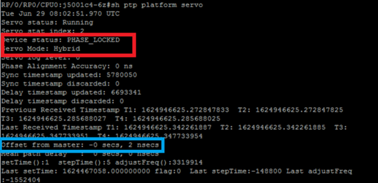
- The Servo status at the end of the servo algorithm must be Phase_Locked. You can see the for the servo status flow. If the Servo mode is Hybrid, SyncE flow must also be taken care of as Phase lock happens only post of Freq_Lock. If the PTP running device is an ordinary MasterClock the above output may not be valid as the Servo algorithm will not run and it doesn’t have to get phase/frequency synchronised from another MasterClock source.
The device status doesn’t go to LOCK unless the offset is within an acceptable range. Do check the ‘Offset from MasterClock’ as well.
Device status:
FREE-RUN/HOLDOVER: Not locked to any clock source.
FREQ_LOCKED: Frequency synchronized to MasterClock
PHASE_LOCKED: Both frequency and phase synchronized to MasterClock
Servo mode:
Hybrid: Use SyncE for frequency synchronization. PTP is used only for phase synchronization.
Default: Use PTP for synchronizing both frequency and phase
Time difference observed by servo algorithm b/w SlaveClock and MasterClock.
Counters for timestamps extracted from PTP packets. Should keep increasing.
Last T1/T2/T3/T4 timestamps (sec.nanosec) extracted from PTP packets. Should be close to each other and uniformly increase.
T1/T4: Sent by MasterClock, T2/T3: Calculated at SlaveClock
Offset Calculated based on PTP timestamps.
Coarse (setTime, stepTime) and fine (adjustFreq) adjustments done by a servo to align itself with the MasterClock.

3. show ptp interfaces brief shows the output port state. It should be MasterClock/SlaveClock state.
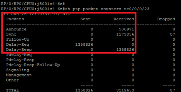
4. The packet drops by ptp must be significantly low.
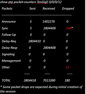
5. Check the packet drop reason:
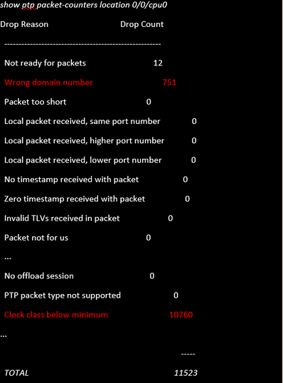
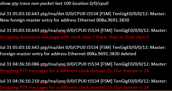
6. Packets not reach PTP.

Are packets reach NPU?
NCS (DNX) platforms: show controllers npu stats traps-all instance all location 0/0/CPU0  | inc 1588

RxTrap1588                                    0    71   0x47        32040   7148566              0

ASR9000 platform: show controller np counters <np> location 0/0/cpu0 | inc PTP

Check for PTP_ETHERNET / PTP_IPV4 counters

Packet drops at NPU (not specific to PTP)

NCS (DNX) platforms: show controllers fia diagshell <np> "diag counters g" location 0/0/cpu0

Shows Rx/TX path statistics along with any drops happening in the NPU

ASR9000 platform: show drops all location <LC>
Check drops at SPP:
show spp node-counters location 0/0/cpu0

# Check for any drop-counters incrementing

NCS (DNX) platforms: show spp trace platform common error last 20 location 0/0/cpu0

Dec 10 02:29:38.322 spp/fretta/err 0/0/CPU0 t2902 FRETTA SPP classify RX:
Failed in dpa_punt_mapper; ssp: 0x1e, inlif: 0x2000, rif: 0x11;
trap_code:FLP_IEEE_1588_PREFIX punt_reason:PTP-PKT pkt_type:L2_LOCALSWITCH rc:
'ixdb' detected the 'fatal' condition 'Not found in database': No such file or directory

ASR9000 platforms:

SPP punt path is simpler in ASR9000 with no risk of a lookup failure.

Drops not expected during packet classification.
7. show ptp packet-counters <interface-id> shows the packet flow. Ensure the syncàDelay_ReqàDelay_Resp is followed (and Follow_Up if it is 2 step clock).

8. Check the flag (S) for the selected interface.
9. Check the QL received. On the selected interface the QLsnd will be DNU in order to prevent loops. To alter your interface preference you can change the priority attribute which is 100 by default.
10. Ensure the ‘Output Driven by’ is the elected SyncE interface.

11. show ptp foreign-MasterClocks brief output is the list of ptp devices participating in the BMCA to become MasterClocks. Check the corresponding flags to see the elected MasterClock. You can see announce messages received from those ports via show ptp packet-counters <interface-id>. The device with the best attributes will win the BMCA. If multiple ports have the same attributes local-priority will be the last tie-breaker. However, automatic topology establishment is also possible with ptp without using local-priority.
12. Ptp does not select the intended MasterClock (BMCA).
Check clock advertised by the remote node:
show ptp foreign-MasterClocks

Interface TenGigE0/9/0/2 (PTP port number 1)

  IPv4, Address X.X.X.X, Unicast

    Configured priority: None (128)

    Configured clock class: None

    Configured delay asymmetry: None

    Announce granted:   every 16 seconds,  1000 seconds

    Sync granted:       every 16 seconds,  1000 seconds

    Delay-resp granted: 64 per-second,     1000 seconds

    Qualified for 4 hours, 50 minutes, 6 seconds

    Clock ID: 1

    Received clock properties:

      Domain: 44, Priority1: 128, Priority2: 128, Class: 6

      Accuracy: 0x21, Offset scaled log variance: 0x4e5d

      Steps-removed: 1, Time source: Atomic, Timescale: PTP

      Frequency-traceable, Time-traceable

      Current UTC offset: 38 seconds (valid)

    Parent properties:

      Clock ID: 1

      Port number: 1
List of qualified and selected MasterClocks:
show ptp foreign-MasterClocks brief

M=Multicast,X=Mixed-mode,Q=Qualified,D=QL-DNU,

GM=GrandMasterClock,LA=PTSF_lossAnnounce,LS=PTSF_lossSync

Interface         Transport Address                   Cfg-Pri  Pri1   State

----------------------------------------------------------------------------

Te0/0/0/12        Ethernet  008a.9691.3830            None     128    M,Q,GM
Check the clock advertised at the MasterClock:
show ptp advertised-clock

Clock ID: 8a96fffe9138d8

Clock properties:

  Domain: 24, Priority1: 128, Priority2: 128, Class: 6

  Accuracy: 0xfe, Offset scaled log variance: 0xffff

  Time Source: Internal (configured, overrides Internal)

  Timescale: PTP (configured, overrides PTP)

  No frequency or time traceability

  Current UTC offset: 0 seconds
13. Ptp not synchronizing with the MasterClock:
•Intended PTP MasterClock selected.

•PTP session established

•But not able to synchronize with the MasterClock

show ptp interface brief

Intf                    Port              Port            Line

Name              Number       State          Encap       State         Mechanism

--------------------------------------------------------------------------------

Te0/0/0/12        1            Uncalibrated Ethernet   up            1-step DRRM


OR occasional PTP flap in the field

Jul 31 09:29:43.114 UTC: ptp_ctrlr[1086]: %PLATFORM-PTP-6-SERVO_EVENTS : PTP Servo state transition from state PHASE_LOCKED to state HOLDOVER

Jul 31 09:30:23.116 UTC: ptp_ctrlr[1086]: %PLATFORM-PTP-6-SERVO_EVENTS : PTP Servo state transition from state HOLDOVER to state FREQ_LOCKED

ul 31 09:35:28.134 UTC: ptp_ctrlr[1086]: %PLATFORM-PTP-6-SERVO_EVENTS : PTP Servo state transition from state FREQ_LOCKED to state PHASE_LOCKED
14. Check if PTP flapped due to packet loss:
show ptp trace last 100 location 0/rp0/cpu0

Aug  1 02:35:01.616 ptp/ctrlr/det 0/RP0/CPU0 t18625 [BMC] Removed clock 0x8a96fffe9138d8 (Ethernet 008a.9691.3830) from node 0/0/CPU0(0x0) from BMC list

Aug  1 02:35:01.616 ptp/ctrlr/det 0/RP0/CPU0 t18625 [BMC] Updated checkpoint record for clock 0x8a96fffe9138d8 (Ethernet 008a.9691.3830) from node 0/0/CPU0(0x0): Checkpoint ID 0x40002f60

Aug  1 02:35:01.616 ptp/ctrlr/det 0/RP0/CPU0 t18625 [BMC] Inserted clock 0x8a96fffe9138d8 (Ethernet 008a.9691.3830) from node 0/0/CPU0(0x0) into BMC list at position 0

Aug  1 02:35:46.035 ptp/ctrlr/sum 0/RP0/CPU0 t18625 [Comms] Received BMC message from node 0/0/CPU0. Comms is active

Aug  1 02:35:46.035 ptp/ctrlr/det 0/RP0/CPU0 t18625 [BMC] Removed clock 0x8a96fffe9138d8 (Ethernet 008a.9691.3830) from node 0/0/CPU0(0x0) from BMC list

Aug  1 02:35:46.035 ptp/ctrlr/det 0/RP0/CPU0 t18625 [BMC] GrandMasterClock removed, local clock better than foreign MasterClock(s)

Aug  1 02:35:46.035 ptp/ctrlr/sum 0/RP0/CPU0 t18625 [Leap Seconds] GrandMasterClock lost

Aug  1 02:35:46.035 ptp/ctrlr/sum 0/RP0/CPU0 t18625 [Platform] Stopping servo

Aug  1 02:35:46.035 ptp/ctrlr/det 0/RP0/CPU0 t18625 [BMC] BMC servo stopped, BMC servo not synced

Aug  1 02:35:46.035 ptp/ctrlr/det 0/RP0/CPU0 t18625 [Comms] Started grandMasterClock message damping timer

Aug  1 02:35:46.035 ptp/ctrlr/sum 0/RP0/CPU0 t18625 [Platform] Sending SlaveClock update to platform. No grandMasterClock available

Aug  1 02:35:46.059 ptp/ctrlr/det 0/RP0/CPU0 t18625 [BMC] Received clock update from the platform. Clock active, not using PTP for frequency, using PTP for time. Current local clock is not a primary ref, sync state is 'Sync' and QL is 'Opt-I/PRC'
15. Check the output of show ptp configuration-errors for any configuration mistakes.
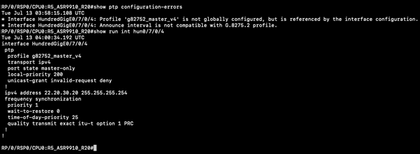
Sample Packet Captures of Sync, Announce, Delay_Req and Delay_Resp Messages
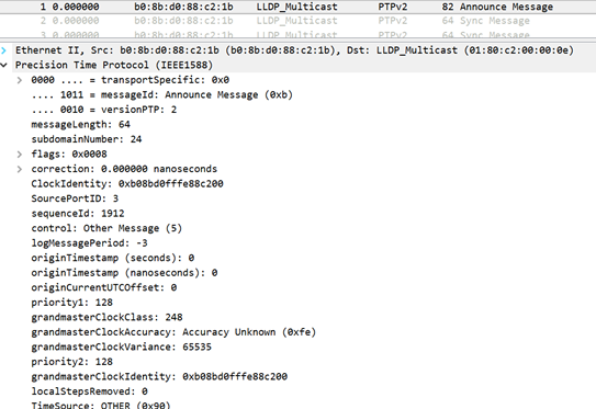
The capture of the Announce message (8275.1) shows the characteristics of the transmitted clock:
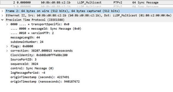
The capture of the Sync message shows the time stamp generation (one-step).
Related Information
- https://www.itu.int/rec/T-REC-G.8275.1/en
- https://www.itu.int/rec/T-REC-G.8275.2/en
- IEEE Standard for 1588v2
- https://www.cisco.com/c/en/us/td/docs/routers/asr9000/software/asr9k_r5-3/sysman/configuration/guide/b-sysman-cg-53xasr9k/b-sysman-cg-53xasr9k_chapter_01100.html
- Technical Support & Documentation - Cisco Systems
Revision History
| Revision | Publish Date | Comments |
|---|---|---|
2.0 |
30-Nov-2021 |
Removed references to sections and added hyperlinks within the doc for ease of access. |
1.0 |
24-Nov-2021 |
Initial Release |
Contributed by Cisco Engineers
- Swetha HaridasulaCisco Advanced Services
- Atahar KhanCisco Advanced Services
- Sekhar Babu HaridasulaCisco Advanced Services
Contact Cisco
- Open a Support Case

- (Requires a Cisco Service Contract)
 Feedback