Introduction
This document describes the IP routing rules on Acano or Cisco Meeting Server (CMS) servers. Acano or CMS servers can have multiple interfaces configured, each with their own default gateway.
Prerequisites
Requirements
Cisco recommends that you have knowledge of these topics:
- CMS components:
- WebBridge (WB)
- Traversal Using Relays around NAT (TURN) server
- CallBridge (CB)
- Basic IP routing
Components Used
The information in this document is based on Cisco Meeting Server on version 2.3.x.
The information in this document was created from the devices in a specific lab environment. All of the devices used in this document started with a cleared (default) configuration. If your network is live, ensure that you understand the potential impact of any command.
Background information
The only limitation here is that the different interfaces on the 4-port switch need to be in different subnets as otherwise you can end up with routing issues on your setup. As an exception to that, hardware X servers that have an ADMIN interface are allowed to have this ADMIN interface in the same subnet as one of the other interfaces (A/B/C/D) as described on the CMS install guide and shown on this note.
Note: Any two interfaces of Cisco Meeting Server must not be put into the same subnet. The only exception is that the ADMIN interface of a physical Acano X-Series server can be on the same subnet as one of the other interfaces (A to D) and is probably a common deployment.
You can run into a situation where you need to know the routing logic when you would receive Binding Requests on your TURN server component for example to verify from which interface the response is sent out.
Which IP Routing Rules Do Apply on Acano/CMS Servers?
The IP routing logic depends on whether the connection is User Datagram Protocol (UDP) or Transmission Control Protocol (TCP) in nature.
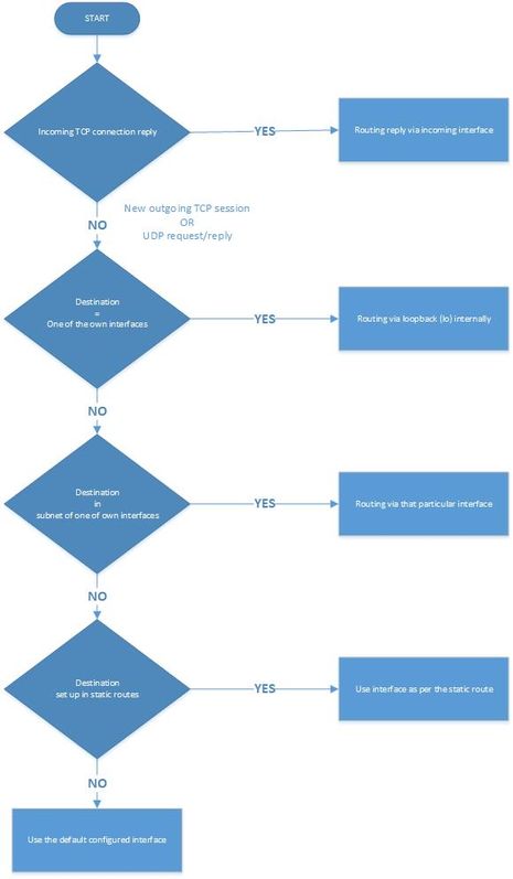
In the case of TCP, whether it is a new connection or a reply to an inbound one, you can find out which IP routing logic is applicable to your case with the use of the flowchart in the image.
Inbound TCP connection reply
The Acano/CMS server replies for an inbound TCP connection on the interface itself on which the request is received (as there is already a TCP connection).
Outbound TCP connection or any outbound UDP packets
For both scenarios, these IP routing rules are followed as per this flowchart (as well as the first step for inbound TCP connection replies).
Note: The logic applies to the creation of new outbound UDP packets or to those sent out in reply to packets received.

How to Show All IP Routing Tables (per Interface)?
By the use of the command ipv4 <interface> on the Mainboard Management Processor (MMP).
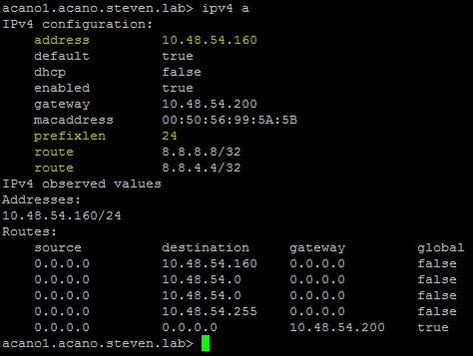
With this you can see the configured IP address and prefix length as well as all of the static routes that are set up for this interface as shown in this Image.
For example here, routes to 8.8.8.8/32 and 8.8.4.4/32 are set up to explicitly go out on this particular interface (a):

You can also see the routes added on the live.json file for the respective interface (A) which maps to eth4.
    "ipv4": {
        "module": {
            "interfaces": {
                "eth4": {
                    "dhcp": "false",
                    "enabled": "true",
                    "default": "true",
                    "macaddress": "00:50:56:99:5A:5B",
                    "address": "10.48.54.160",
                    "prefixlen": "24",
                    "gateway": "10.48.54.200",
                    "routes": {
                        "8=8=8=8-32": {
                            "address": "8.8.8.8",
                            "prefixlen": "32"
                        },
                        "8=8=4=4-32": {
                            "address": "8.8.4.4",
                            "prefixlen": "32"
                        }
}Note: In the live.json file, the interfaces A-D (from the MMP) map to eth4-eth1 so interface A maps to eth4 and interface D maps to eth1. The other snippet is a snippet of an X-series server where you can see the ADMIN interface is in the section of mmp under ipv4 instead of module as shown for the other interfaces.
    "ipv4": {
        "mmp": {
            "interfaces": {
                "eth0": {
                    "macaddress": "44:4A:65:00:13:00",
                    "dhcp": "false",
                    "enabled": "true",
                    "default": "true",
                    "address": "10.48.79.72",
                    "prefixlen": "24",
                    "gateway": "10.48.79.200"
                }
In order to add or delete static routes to a specific interface, you can use the command ipv4 <interface> route (add | del) <address>/<prefix length>.
How to Check and Change the Default Interface?
By default interface A is the default one if you start with a blank configuration.
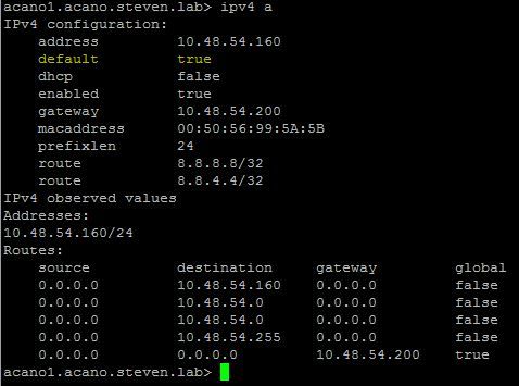
You can verify this on the interface by the default parameter as highlighted on this image:
This is the output of the command ipv4 <interface> on MMP.

Note: If this value is set to true, then this is the default interface as in the image.
You can also see from the live.json whether the interface A (which maps to eth4), is set up as the default interface.
    "ipv4": {
        "module": {
            "interfaces": {
                "eth4": {
                    "dhcp": "false",
                    "enabled": "true",
                    "default": "true",
                    "macaddress": "00:50:56:99:5A:5B",
                    "address": "10.48.54.160",
                    "prefixlen": "24",
                    "gateway": "10.48.54.200",
                    "routes": {
                        "8=8=8=8-32": {
                            "address": "8.8.8.8",
                            "prefixlen": "32"
                        },
                        "8=8=4=4-32": {
                            "address": "8.8.4.4",
                            "prefixlen": "32"
In order to change the default interface, you can use the command ipv4 <interface> default, but ensure that you have the right static route(s) in place to accommodate this change otherwise the routing is affected.
Example:

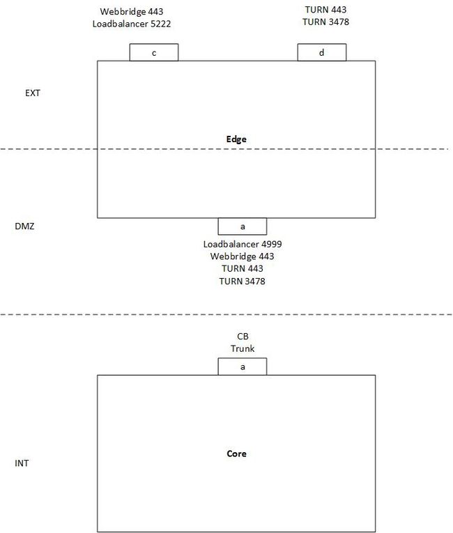
The Image represents an example of a single split server setup with one Core and one Edge server with these requirements:
- Core server can only connect to the DMZ interface (A) and not to the public ones (C & D).
- TURN server component needs to listen on 443 just like the WebBridge (and thus different interfaces are required to avoid a port clash).
In this example no special routing has been set up and no different default interface has been specified so it defaults to interface A on the Edge server.
Situation:
- WebRTC clients are able to log in but calls fail
- Binding and Allocate Requests from CB to the TURN server do get a Success responses
- Binding and Allocate Requests from external WebRTC clients to the TURN server arrive but do not get Success responses
Explanation:
- As the WB and Loadbalancer (LB) only respond to inbound TCP connections and do not initiate outbound ones themselves, this routing does not pose an issue.
Note: As both services are on the same server the WB can still make an outbound connection to the LB but that happens internally.
- Also the Binding and Allocate Requests from the CB to the TURN server DMZ IP do get responded as either they are in the same subnet (Edge interface A and Core interface A) or because there is no static route set up and it just sends it out on the default interface (interface A in this case).
- For the external Binding and Allocate Requests, it does not have any static routes and thus uses the default interface A to route out the traffic (which results in not reaching the external client).
Solution:
- Add interface B on the Edge servers and use interface A for internal WB connection (as well as the LB) and interface B for the internal TURN server connection (to avoid the port clash on 443 is used for both TURN and WB). Configure this with the next commands on the MMP (and correct the TURN configuration on your callbridges accordingly for the new serverAddress of interface B).
ipv4 b add <IP-address>/<prefix length> <default-gateway>
ipv4 b enable
turn disable
turn listen d b
turn enable
- Add static routes to route traffic from the Edge servers out to the internal Core server with the command:
ipv4 b route add <address>/<prefix length>
Note: As the LB and WB only react on inbound TCP connections, you only need to set up the routing for the UDP packets for TURN and thus you do this on interface B. Also ensure that the gateway on interface B can route it to the CB of course.
For example if the Core server has the IP address 192.168.0.100/24, the command must either be ipv4 b route add 192.168.0.100/24 or ipv4 b route add 192.168.0.100/32.
- Make your external TURN server interface (D) as the default interface for the traffic.
ipv4 d default
Verify
There is currently no verification procedure available for this configuration.
Troubleshoot
There is currently no specifictroubleshootinginformation available for this configuration.
Related Information


 Feedback