Implement IPv6 in Software-Defined Access
Available Languages
Download Options
Bias-Free Language
The documentation set for this product strives to use bias-free language. For the purposes of this documentation set, bias-free is defined as language that does not imply discrimination based on age, disability, gender, racial identity, ethnic identity, sexual orientation, socioeconomic status, and intersectionality. Exceptions may be present in the documentation due to language that is hardcoded in the user interfaces of the product software, language used based on RFP documentation, or language that is used by a referenced third-party product. Learn more about how Cisco is using Inclusive Language.
Contents
Introduction
This document describes how to implement IPv6 in Cisco® Software-Defined Access (SD-Access).
Background Information
IPv4 was released in 1983 and is still in use for the majority of internet traffic. The 32 bits IPv4 addressing allowed over 4 billion unique combinations. However, due to the increase in the number of internet-connected clients, there is a shortage of unique IPv4 addresses. In the 1990s, the exhaustion of IPv4 addressing became inevitable.
In anticipation of this, Internet Engineering Taskforce introduced the IPv6 standard. IPv6 utilises 128 bits and offers 340 undecillion unique IP addresses, which is more than enough to cater to the need of connected devices that grow. As more and more modern end-point devices support dual-stack and or single IPv6 stack, it is crucial for any organization to be ready for the adoption of IPv6. This means that the entire infrastructure must be ready for IPv6. Cisco SD-Access is the evolution from traditional campus designs to the networks that directly implement the intent of an organization. Cisco Software Defined Networks is now ready to onboard dual-stack (IPv6 Devices).
A major challenge for any organization in the adoption of IPV6 is the change management and complexities associated with the migration of legacy IPv4 systems to IPv6. This paper covers all the details about IPv6 feature support on Cisco SDN, strategy, and critical pit spot points, which need to be taken care of when you adopt IPv6 with Cisco Software Defined Networks.
In August 2019, Cisco DNA Centre version 1.3 was first introduced with the support of IPv6. In this release, the Cisco SD-Access campus network supported the host IP address with wired and wireless clients in IPv4, IPv6 or IPv4v6 Dual-stack from the overlay fabric network. The solution is to continuously evolve to bring new features and functionalities that easily onboard the IPv6 for any enterprise.
Cisco SD-Access with IPv6 Architecture
Fabric technology, an integral part of SD-Access, provides wired and wireless campus networks with programmable overlays and easy-to-deploy network virtualization, that permit a physical network to host one or more logical networks to meet the design intent. In addition to network virtualization, fabric technology in the campus network enhances control of communications, that provides software-defined segmentation and policy enforcement based on user identity and group membership. The entire Cisco SDN solution runs on the DNA of the fabric. Hence, it is critical to understand each pillar of the solution with respect to IPv6 support.
• Underlay - IPv6 functionality for Overlay has a dependency on the underlay as the IPv6 overlay makes use of the IPv4 underlay IP addressing to create LISP control plane and VxLAN data plane tunnels. You can always enable the dual-stack for the underlay routing protocol, just the SD-Access overlay LISP only depends on the IPv4 routing. (This requirement is for the current version of DNA-C (2.3.x) and is removed in later releases where underlay can be dual-stack or single IPv6 stack only).
• Overlay - When it comes to the overlay, SD-Access supports both IPv6-only wired and wireless endpoints. That IPv6 traffic is encapsulated in IPv4 and VxLAN header within the SD-Access fabric until they reach the fabric border nodes. The fabric border nodes decapsulate the IPv4 and VxLAN header, which pursues the normal IPv6 unicast routing process from then.
• Control Plane Nodes - The Control Plane node is configured to allow all IPv6 host subnets and the /128 host routes within the subnet ranges to be registered in its mapping database.
• Border nodes - On the border nodes, IPv6 BGP peering with fusion devices is enabled. The border node decapsulates the IPv4 header from the fabric egress traffic while the ingress IPv6 traffic is encapsulated with the IPv4 header by the border nodes as well.
• Fabric Edge – All the SVIs which are configured in Fabric Edge have to be IPv6. This configuration is pushed by the DNA Center Controller.
• Cisco DNA Center – The Cisco DNA Center physical interfaces do not support dual-stack as of the time this document is published. It can only deploy in a single stack with either IPv4 or IPv6 only in the management and or enterprise interfaces of the DNA Center.
• Clients – Cisco® Software-Defined Access (SD-Access) supports dual-stack (IPv4&IPv6) or single stack either IPv4 or IPv6. However, in the case of an IPv6 single stack is deployed, DNA Center still requires to create a dual-stack pool to support an IPv6-only client. The IPv4 in the dual-stack pool is a dummy address only as the IPv6 the client is expected to disable the IPv4 address.
IPv6 Overlay Architecture in Cisco Software-Defined Access.
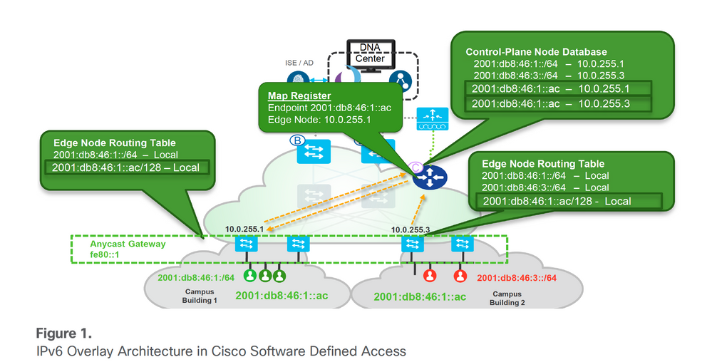 IPv6 Overlay Architecture
Enable IPv6 with Cisco DNA-Center
There are two ways to enable the IPv6 pool in the Cisco DNA Center:
1. Create a new dual-stack IPv4/v6 Pool - greenfield
2. Edit IPv6 on the IPv4 pool that already exists - brownfield migration
The current release (up to 2.3.x) of DNA Center does not support IPv6 only a pool if the user plans to support a single/native IPv6 address-only client, a dummy IPv4 address needs to associate with the IPv6 pool. Please note that from the deployed IPv4 pool that already exists with a site associated with it, and edit the pool with an IPv6 address, DNA Center provides the migration option for the SD-Access Fabric which requires the user to reprovision the fabric for that site. A warning indicator is displayed in the Fabric where the site belongs and indicates that Fabric needs to ‘reconfigure fabric’. Please see these images for samples.
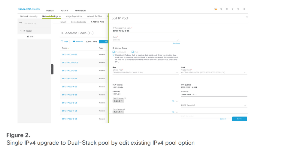 Single IPv4 pool upgrade to dual-stack pool by editing IPv4 pool option
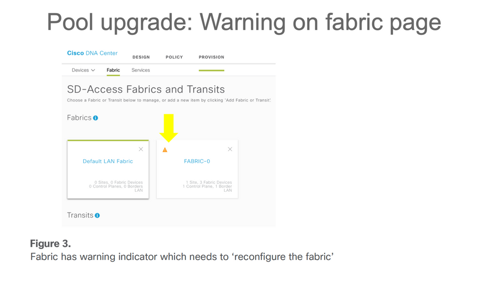 Fabric has warning indicator which needs to 'reconfigure the fabric'
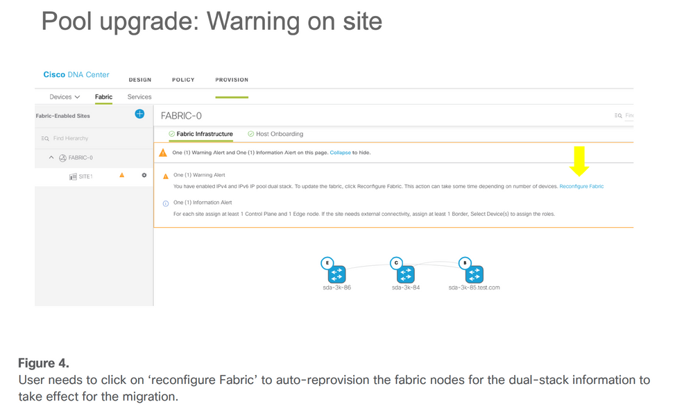 User needs to click on 'reconfigure fabric' to auto-reprovision the fabric nodes for the dual-stack configuration to take effect as part of migration process
Design Considerations with IPv6 in Cisco SD-Access
Though for the Cisco SD-Access clients, they can run with dual-stack or IPv6-only network settings. The current SD-Access fabric implementation with DNA Center SW version up to 2.3.x.x has some considerations about the IPv6 deployment.
• Cisco SD-Access supports IPv4 underlay routing protocols. Thus, the IPv6 client traffic is transported when it is encapsulated it within IPv4 headers. This is a requirement for current LISP software deployment. But it does not mean that the underlay cannot enable IPv6 routing protocol, just the SD-Access overlay LISP does not run on its dependence.
• IPv6 native multicast is not supported due to the fabric underlay can only be IPv4 at present.
• Guest wireless can only run with the dual stack. Because of the current ISE release (for example, up to 3.2), the IPv6 guest portal is not supported, thus an IPv6-only guest client won’t be able to get authenticated.
• IPv6 Application QoS Policy automation is not supported in the current DNA Center release. This document describes the steps needed to implement IPv6 QoS for wired and wireless dual-stack clients in Cisco SD-Access which had been deployed for one of the users on large scale.
• Wireless client rate-limiting feature for downstream and upstream traffic either per SSID or per client based on policy is supported for IPv4 (TCP/UDP) and IPv6 (TCP only). IPv6 UDP rate limiting is not yet supported.
• IPv4 pool can be upgraded to a dual-stack pool. But a dual-stack pool cannot be downgraded to an IPv4 pool. If the user wants to remove the dual-stack pool back to IPv4 single-stack pool it needs to release the whole dual-stack pool.
• Single IPv6 is not supported yet while only IPv4 or dual-stack pool can be created in the current DNA Center
• The platform of Cisco IOS®-XE is a minimal software version requirement of 16.9.2 and later.
• IPv6 Guest wireless is not supported yet in Cisco IOS-XE platforms while AireOS (8.10.105.0+) supports a workaround.
• Dual-stack pool cannot be assigned in the INFRA_VN where only AP or Extended Node pool can be assigned.
• LAN automation does not support IPv6 yet.
Besides the limitations mentioned previously, when you design an SD-Access fabric with IPv6 enabled, you must always keep the
scalability of each fabric component in mind. If an endpoint has multiple IPv4 or IPv6 addresses, then each address is counted as an individual entry.
Fabric host entries include access points and classic and policy-extended nodes.
Additional border node scale considerations:
/32 (IPv4) or /128 (IPv6) entries are used when the border node forwards traffic from outside the fabric to a host in the fabric.
For all switches except Cisco Catalyst 9500 Series High-Performance Switches and Cisco Catalyst 9600 Series Switches:
● IPv4 uses one TCAM entry (fabric host entries) for every IPv4 IP address.
● IPv6 uses two TCAM entries (fabric host entries) for every IPv6 IP address.
For the Cisco Catalyst 9500 Series High-Performance Switches and Cisco Catalyst 9600 Series Switches:
● IPv4 uses one TCAM entry (fabric host entries) for every IPv4 IP address.
● IPv6 uses one TCAM entry (fabric host entries) for every IPv6 IP address.
And some of the endpoints do not support DHCPv6 such as Android OS-based smartphones that rely on SLAAC to get IPv6 addresses. A single endpoint could end up with more than two IPv6 addresses. This behavior consumes more hardware resources on each fabric node, especially for the fabric border and control nodes. For example, every time the border node wants to send traffic to the edge nodes for any endpoint, it installs a host route in the TCAM entry and burns a VXLAN adjacency entry in the HW TCAM.
Wired and Wireless Client Connections and Call Flows
Once the client is connected to the Fabric Edge, there are different ways in which it gets the IPv6 addresses. This section covers the most common way to client IPv6 addressing, that is SLAAC and DHCPv6.
IPv6 Address Assignment – SLAAC
The SLAAC in SDA isn’t different from the standard SLAAC process flow. For SLAAC to work properly, the IPv6 client must be configured with a link-local address in its interface, how the client automatically configures itself with the link-local address is out of this paper’s scope.
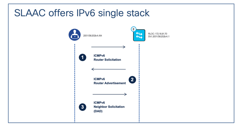 IPv6 address assignment – SLAAC
Call Flow Description:
Step 1. After the IPv6 client configures itself with an IPv6 link-local address, the client sends ICMPv6 Router Solicitation (RS) message to Fabric Edge. The purpose of this message is to gain the global unicast prefix of its connected segment.
Step 2. After the fabric edge receives the RS message, it responds back with an ICMPv6 Router Advertisement (RA) message which contains the global IPv6 unicast prefix and its length inside.
Step 3. Once the client gets the RA message, it combines the IPv6 global unicast prefix with its EUI-64 interface identifier to generate its unique IPv6 global unicast address and set its gateway to the link-local address of the fabric edge’s SVI which is related to the client’s segment. Then the client sends out an ICMPv6 Neighbor Solicitation message to perform duplicate address detection (DAD) to make sure the IPv6 address it gets is unique.

Note: All the SLAAC-related messages are encapsulated with the client’s and the fabric node’s SVI IPv6 link-local address.
IPv6 Address Assignment – DHCPv6
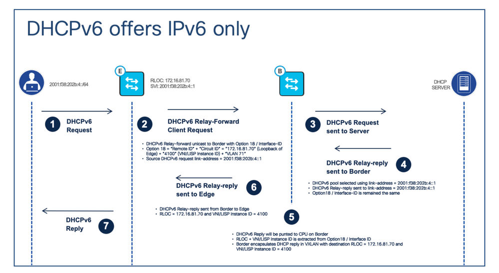 IPv6 address assignment – DHCPv6
Call Flow Description:
Step 1. The client sends out the DHCPv6 request to the fabric edge.
Step 2. When the fabric edge receives the DHCPv6 request, it’ll use the DHCPv6 Relay-forward message to unicast the request to the fabric border with DHCPv6 option 18. Compared to DHCP option 82, the DHCPv6 option 18 encodes both “Circuit ID” and “Remote ID” together. The LISP Instance ID/VNI, IPv4 RLOC and endpoint VLAN are encoding
inside.
Step 3. The fabric border decapsulates the VxLAN header and unicasts the DHCPv6 packet to the DHCPv6 server.
Step 4. The DHCPv6 server receives the relay-forward message, it uses the source link address (DHCPv6 relay agent/client’s gateway) of the message to select the IPv6 IP pool to assign the IPv6 address. Then sends out the DHCPv6 relay-reply message back to the client’s gateway address. Option 18 remains unchanged.
Step 5. When the fabric border receives the relay-reply message, it extracts the RLOC and LISP instance/VNI from option 18. Fabric border encapsulates the relay-reply message in VxLAN with a destination which it extracted from option 18.
Step 6. The fabric border sends the DHCPv6 Relay-reply message to the fabric edge to which the client connects.
Step 7. When fabric edge receives the DHCPv6 relay-reply message, it decapsulates the message’s VxLAN header and forwards the message to the client. Then the client knows its assigned IPv6 address.
IPv6 Communication in Cisco SD-Access
IPv6 communication uses the standard LISP-based control plane and VXLAN-based Data plane communication methods. With the current implementation in Cisco SD-Access LISP and VXLAN uses the outer IPv4 header to carry the IPv6 packets inside. This image captures this process.
 Outer IPv4 header carrying the IPv6 packets inside
This means that all the LISP queries use the IPv4 native packet, while the control plane node table has details about the RLOC with both IPv6 and IPv4 IP addresses of the endpoint. This process is explained in detail in the next section from a Wireless endpoint perspective.
Wireless IPv6 Communication in Cisco SD-Access
The wireless communication relies on two specific components Access Points and Wireless LAN controllers apart from typical Cisco SD-Acces Fabric components. Wireless Access Points create a CAPWAP (Control and Provisioning of wireless access points) tunnel with the Wireless LAN Controller (WLC). While the client traffic exists at the Fabric Edge, other control plane communication which includes Radio stats is managed by the WLC. From an IPv6 perspective, both the WLC and AP must have the IPv4 addresses and all CAPWAP communication uses these IPv4 addresses. While the Non-Fabric WLC and AP support IPv6 communication, Cisco SD-Access uses the IPv4 for all communication that carries any client IPv6 traffic inside IPv4 packets. This means that assigned AP pools under Infra VN cannot be mapped with IP pools which are dual-stack and an error is thrown if any attempt is made to this mapping. Wireless communication within Cisco SDA can be divided into these major tasks:
• Access Point Onboarding
• Client on-boarding
Look at these events from an IPv6 perspective.
Access Point Onboarding
This process remains the same for IPv6 as IPv4, as both WLC and AP have IPv4 addresses and steps included here:
1. FE port is configured to onboard AP.
2. AP connects to FE port, and via CDP AP notifies FE about its presence (this allows FE to assign the right VLAN).
3. AP gets the IPv4 address from the DHCP server and FE registers AP and updates Control Plane (CP node) with AP details.
4. AP joins WLC via Traditional Methods (like DHCP Option 43).
5. WLC checks if AP is Fabric capable and Queries the Control Plane for AP RLOC Information (e.g RLOC Requested/Response Received).
6. CP replies with the RLOC IP of the AP to the WLC.
7. WLC registers the AP MAC in CP.
8. CP updates the FE with the details from WLC about the AP (this tells FE to initiate the VXLAN tunnel with the AP).
FE processes the information and creates a VXLAN tunnel with AP. At this point, AP advertises Fabric Enabled SSID.

Note: In case the AP broadcasts the Non-Fabric SSIDs and does not broadcast Fabric SSID, please check for the VXLAN tunnel between the Access Point and the Fabric Edge node.
Also, note the AP to WLC communication always happens via Underlay CAPWAP and all WLC to AP communication uses VXLAN CAPWAP via overlay. This means, if you capture packets that go from AP to WLC, you only see CAPWAP while the reverse traffic has a VXLAN tunnel. See this example for communication between AP and WLC.
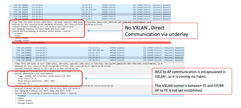 Packet Captures from AP to WLC (CAPWAP Tunnel) vs WLC to AP (VxLAN Tunnel in the Fabric)
Client Onboarding
Dual-Stack/IPv6 Client on-boarding process remains the same but the client uses the IPv6 address assignment methods like SLAAAC/DHCPv6 to get the IPv6 addresses.
1. Client joins the Fabric and enables SSID on the AP.
2. WLC knows the AP RLOC.
3. Client Authenticates and WLC registers the Client L2 details with CP and updates AP.
4. Client initiates the IPv6 Addressing from configured methods – SLAAC/DHCPv6.
5. FE triggers IPv6 client registration to CP HTDB.
AP to. FE and FE to other destinations use the VXLAN and LISP IPv6 encapsulation within IPv4 frames.
Client-Client Communication with IPv6
The image here summarises the IPv6 wireless client communication process with another IPv6 wired client. (this assumes the client is authenticated and got the IPv6 address via configured methods).
1. Client Sends the 802.11 frames to the AP with IPv6 payload.
2. AP removes the 802.11 headers and sends the original IPv6 payload in the IPv4 VXAN tunnel to fabric Edge.
3. Fabric Edge uses the MAP request to identify the destination and sends the frame to the destination RLOC with IPv4 VXLAN.
4. At the destination Switch, the IPv4 VXLAN header is removed and the IPv6 packet is sent to the client.
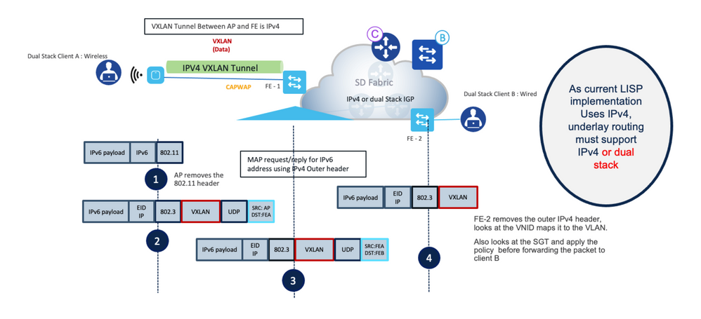 Dual-stack wireless client to dual-stack wired client packet flows
Look in-depth at this process with the packet captures and refer to the image for IP addresses and MAC address details. Please note this setup uses both Dual-Stack clients connected with the same Access points but mapped with different IPv6 subnets (SSIDs).
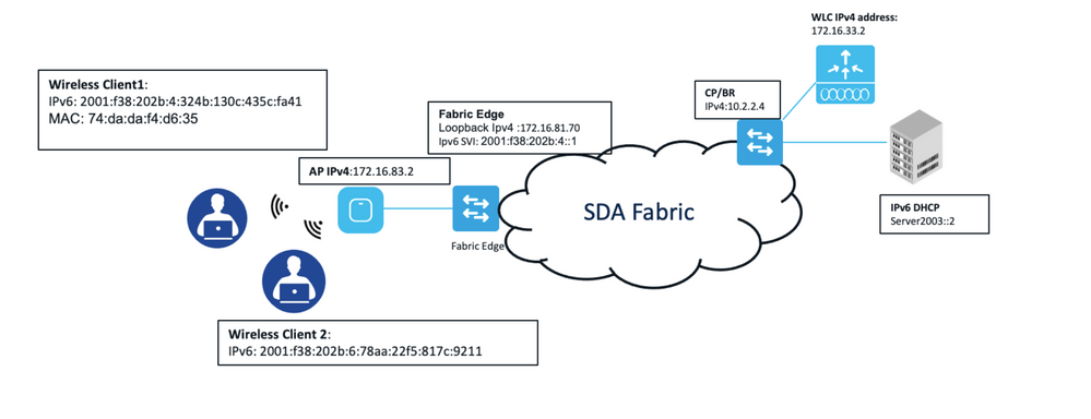 Sample SD-Access Fabric network IP addresses and MAC addresses detail

Note: For any IPv6 communication outside fabric, for example, DHCP/DNS, IPv6 routing must be enabled between the border and Non-fabric infrastructure.
Step 0. The client authenticates and gets the IPv6 address from the configured methods.
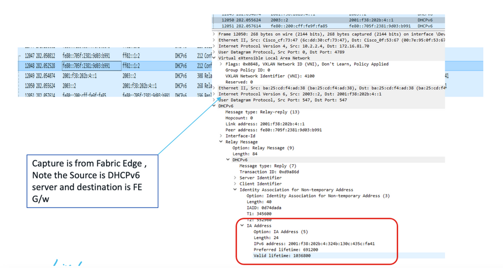 Packet Capture from DHCPv6 server to Fabric Edge Node
Step 1. The wireless client sends the 802.11 frames to the Access point with the IPv6 payload.
Step 2. The access point removes the wireless header and sends the packet to the Fabric edge. This uses the VXLAN tunnel header which is IPv4 based as Access Point has the IPv4 address.
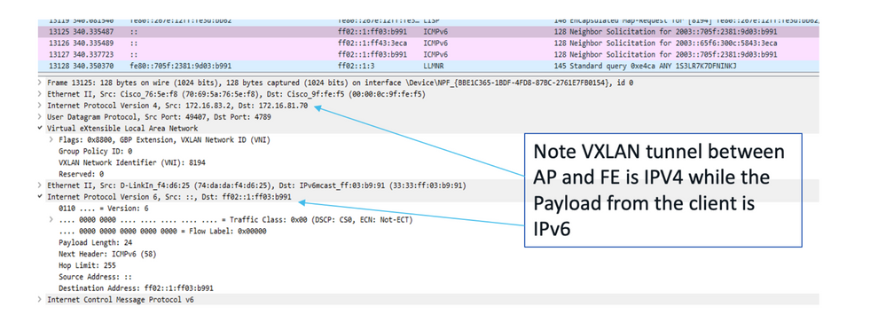 Packet Capture for the VxLAN tunnel between FE and AP
Step 3 (a). Fabric Edge registers the IPv6 client with the Control Plane. This uses the IPv4 registration method with details of the IPv6 client inside.
 Packet Capture for FE registers with Control Plane for IPv6 client
Step 3 (b). FE send the MAP request to the control plane to identify the destination RLOC.
 Packet Capture from FE to CP with MAP registration messages
Fabric Edge also maintains the MAP cache for known IPv6 clients, as shown in this image.
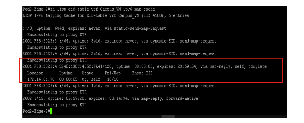 Fabric Edge screen output of IPv6 overlay map-cache information
Step 4. The packet is forwarded to the destination RLOC with the IPv4 VXLAN that carries the original IPv6 payload inside. As both clients are connected to the same AP, the IPv6 ping takes this path.
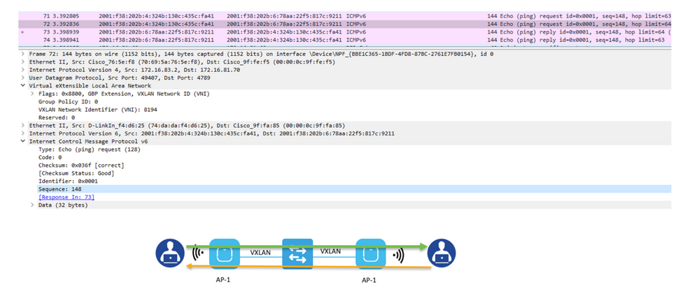 Packet Capture for IPv6 ping between two wireless clients registered to the same AP
This image summarizes the IPv6 communication from the wireless client perspective.
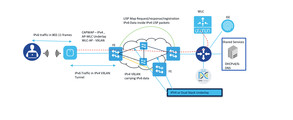 The figure summarizes the IPv6 communication from the wireless client perspective

Note: IPv6 Guest Access (web Portal) via Cisco Identity Services is not supported due to limitations on ISE.
Dependency Matrix
It is important to note the dependencies and support for IPv6 from different wireless components which are part of Cisco SD-Access. The table in this image summarises this feature matrix.
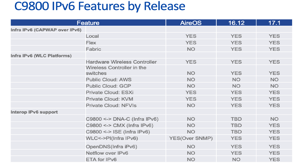 Cat9800 WLC IPv6 Features by Release
Monitor the Control Plane for IPv6
Once you enable the IPv6, you start to see additional entries about host IPv6 in the MS/MR servers. As a host can have multiple IPv6 IP addresses, your MS/MR lookup table has entries for all the IP addresses. This is combined with the IPv4 table that already exists.
You have to login into the device CLI and issue these commands to check all the entries.
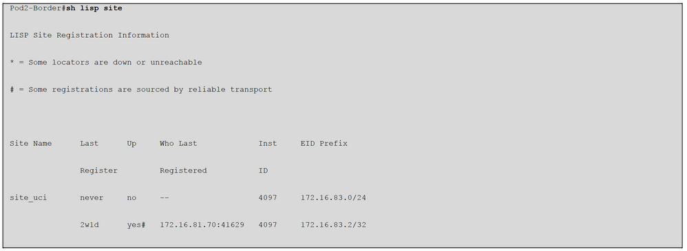
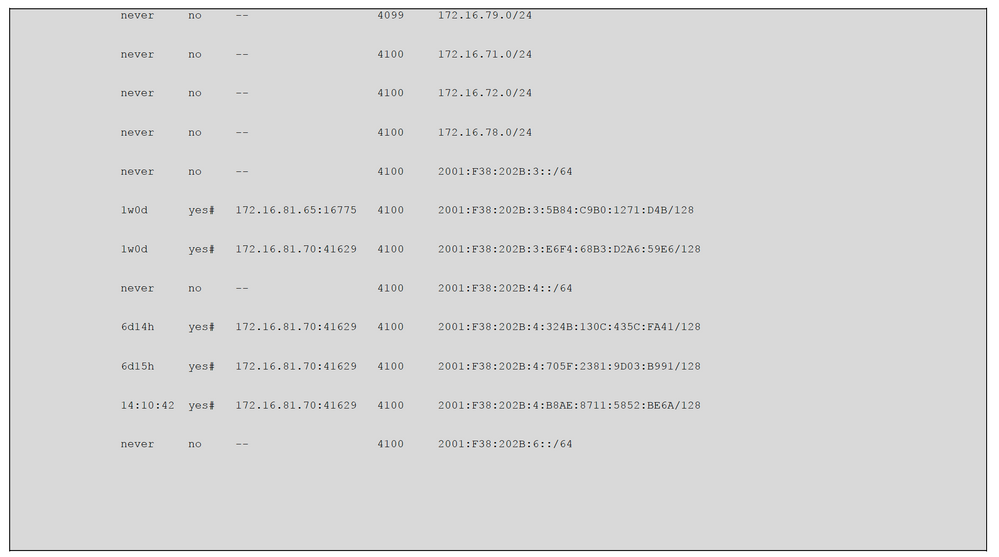
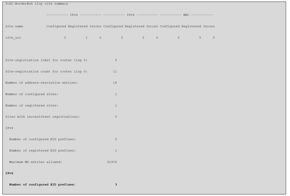

You can also check the details about the host IPv6 details via assurance.
IPv6 QoS Implementation in Cisco SD-Access
Current Cisco DNA Center release (up to 2.3.x) does not support IPv6 QoS Application Policy automation. However, users can manually create IPv6 wired and wireless templates and push the QoS template into Fabric Edge nodes. Since DNA Center automates the IPv4 QoS policy on all physical interfaces once applied. You can manually insert a class map (that matches IPv6 ACL) before “class-default” via a template.
Here is the sample wired IPv6 QoS-enabled template integrated with DNA Center-generated policy configuration:
!
interface GigabitEthernetx/y/z
service-policy input DNA-APIC_QOS_IN
class-map match-any DNA-APIC_QOS_IN#SCAVENGER <<< Provisioned by DNAC
match access-group name DNA-APIC_QOS_IN#SCAVENGER__acl
match access-group name IPV6_QOS_IN#SCAVENGER__acl <<< Manually add
!
ipv6 access-list IPV6_QOS_IN#SCAVENGER__acl <<< Manually add
sequence 10 permit icmp any any
!
Policy-map DNA-APIC_QOS_IN
class IPV6_QOS_IN#SCAVENGER__acl <<< manually add
set dscp cs1
For wireless QoS policy, Cisco DNA Center with current release (up to 2.3.x) will provision IPv4 QoS only
and apply IPv4 QoS into the WLC (Wireless LAN Controller). It doesn’t automate IPv6 QoS.
© 2021 Cisco and/or its affiliates. All rights reserved. Page 20 of 24
Below is the sample wireless IPv6 QoS template. Please make sure to apply the QoS policy into the wireless SVI
interface from the wireless VLAN:
ipv6 access-list extended IPV6_QOS_IN#TRANS_DATA__acl
remark ### a placeholder ###
!
ipv6 access-list extended IPV6_QOS_IN#REALTIME
remark ### a placeholder ###
!
ipv6 access-list extended IPV6-QOS_IN#TUNNELED__acl
remark ### a placeholder ###
!
ipv6 access-list extended IPV6_QOS_IN#VOICE
remark ### a placeholder ###
!
ipv6 access-list extended IPV6_QOS_IN#SCAVENGER__acl
permit icmp any any
!
ipv6 access-list extended IPV6_QOS_IN#SIGNALING__acl
remark ### a placeholder ###
!
ipv6 access-list extended IPV6_QOS_IN#BROADCAST__acl
remark ### a placeholder ###
!
ipv6 access-list extended IPV6_QOS_IN#BULK_DATA__acl
permit tcp any any eq ftp
permit tcp any any eq ftp-data
permit tcp any any eq 21000
permit udp any any eq 20
!
ipv6 access-list extended IPV6_QOS_IN#MM_CONF__acl
remark ms-lync
permit tcp any any eq 3478
permit udp any any eq 3478
permit tcp range 5350 5509
permit udp range 5350 5509
!
ipv6 access-list extended IPV6_QOS_IN#MM_STREAM__acl
remark ### a placeholder ###
!
ipv6 access-list extended IPV6_QOS_IN#OAM__acl
remark ### a placeholder ###
!
=-=-=-=-=-=-=-=-=-=-=-=-=-=-=-=-=-=-=-=-=-=-=-=-=-=-=-=-=-=-=-=-=-=-=-=-=-=-=-=-
!
class-map match-any IPV6_QOS_IN#TRANS_DATA
match access-group name IPV6_QOS_IN#TRANS_DATA__acl
!
class-map match-any IPV6_QOS_IN#REALTIME
match access-group name IPV6_QOS_IN#TUNNELED__acl
!
class-map match-any IPV6_QOS_IN#TUNNELED
match access-group name IPV6_QOS_IN#TUNNELED__acl
!
class-map match-any IPV6_QOS_IN#VOICE
match access-group name IPV6_QOS_IN#VOICE
!
class-map match-any IPV6_QOS_IN#SCAVENGER
match access-group name IPV6_QOS_IN#SCAVENGER__acl
!
class-map match-any IPV6_QOS_IN#SIGNALING
match access-group name IPV6_QOS_IN#SIGNALING__acl
class-map match-any IPV6_QOS_IN#BROADCAST
match access-group name IPV6_QOS_IN#BROADCAST__acl
!
class-map match-any IPV6_QOS_IN#BULK_DATA
match access-group name IPV6_QOS_IN#BULK_DATA__acl
!
class-map match-any IPV6_QOS_IN#MM_CONF
© 2021 Cisco and/or its affiliates. All rights reserved. Page 21 of 24
match access-group name IPV6_QOS_IN#MM_CONF__acl
!
class-map match-any IPV6_QOS_IN#MM_STREAM
match access-group name IPV6_QOS_IN#MM_STREAM__acl
!
class-map match-any IPV6_QOS_IN#OAM
match access-group name IPV6_QOS_IN#OAM__acl
!
=-=-=-=-=-=-=-=-=-=-=-=-=-=-=-=-=-=-=-=-=-=-=-=-=-=-=-=-=-=-=-=-=-=-=-=-=-=-=-=-
policy-map IPV6_QOS_IN
class IPV6_QOS_IN#VOICE
set dscp ef
class IPV6_QOS_IN#BROADCAST
set dscp cs5
class IPV6_QOS_IN#REALTIME
set dscp cs4
class IPV6_QOS_IN#MM_CONF
set dscp af41
class IPV6_QOS_IN#MM_STREAM
set dscp af31
class IPV6_QOS_IN#SIGNALING
set dscp cs3
class IPV6_QOS_IN#OAM
set dscp cs2
class IPV6_QOS_IN#TRANS_DATA
set dscp af21
class IPV6_QOS_IN#BULK_DATA
set dscp af11
class IPV6_QOS_IN#SCAVENGER
set dscp cs1
class IPV6_QOS_IN#TUNNELED
class class-default
set dscp default
=-=-=-=-=-=-=-=-=-=-=-=-=-=-=-=-=-=-=-=-=-=-=-=-=-=-=-=-=-=-=-=-=-=-=-=-=-=-=-=-
interface Vlan1xxx < = = (wireless VLAN)
service-policy input IPV6_QOS_IN
end
Troubleshoot IPv6 in Cisco SD-Access
Troubleshoot SD-Access IPv6 is quite like IPv4, you can always use the same command with different keyword options to achieve the same goal. This shows some commands that frequently be used to troubleshoot SD-Access.
Pod2-Edge-2#sh device-tracking database
Binding Table has 24 entries, 12 dynamic (limit 100000)
Codes: L - Local, S - Static, ND - Neighbor Discovery, ARP - Address Resolution Protocol, DH4 - IPv4 DHCP, DH6 - IPv6 DHCP, PKT - Other
Packet, API - API created
Preflevel flags (prlvl):
0001:MAC and LLA match 0002:Orig trunk 0004:Orig access
0008:Orig trusted trunk 0010:Orig trusted access 0020:DHCP assigned

0040:Cga authenticated 0080:Cert authenticated 0100:Statically assigned
Network Layer Address Link Layer Address Interface vlan prlvl age state Time left
DH4 172.16.83.2 7069.5a76.5ef8 Gi1/0/1 2045 0025 5s REACHABLE 235 s(653998 s)
L 172.16.83.1 0000.0c9f.fef5 Vl2045 2045 0100 22564mn REACHABLE
ARP 172.16.79.10 74da.daf4.d625 Ac0 71 0005 49s REACHABLE 201 s try 0
L 172.16.79.1 0000.0c9f.f886 Vl79 79 0100 22562mn REACHABLE
L 172.16.78.1 0000.0c9f.fa09 Vl78 78 0100 9546mn REACHABLE
DH4 172.16.72.101 000c.29c3.16f0 Gi1/0/3 72 0025 9803mn STALE 101187 s
L 172.16.72.1 0000.0c9f.f1ae Vl72 72 0100 22562mn REACHABLE
L 172.16.71.1 0000.0c9f.fa85 Vl71 71 0100 22562mn REACHABLE
ND FE80::7269:5AFF:FE76:5EF8 7069.5a76.5ef8 Gi1/0/1 2045 0005 12s REACHABLE 230 s
ND FE80::705F:2381:9D03:B991 74da.daf4.d625 Ac0 71 0005 107s REACHABLE 145 s try 0
L FE80::200:CFF:FE9F:FA85 0000.0c9f.fa85 Vl71 71 0100 22562mn REACHABLE
L FE80::200:CFF:FE9F:FA09 0000.0c9f.fa09 Vl78 78 0100 9546mn REACHABLE
L FE80::200:CFF:FE9F:F886 0000.0c9f.f886 Vl79 79 0100 87217mn DOWN
L FE80::200:CFF:FE9F:F1AE 0000.0c9f.f1ae Vl72 72 0100 22562mn REACHABLE
ND 2003::B900:53C0:9656:4363 74da.daf4.d625 Ac0 71 0005 26mn STALE 451 s
ND 2003::705F:2381:9D03:B991 74da.daf4.d625 Ac0 71 0005 3mn REACHABLE 49 s try 0
ND 2003::5925:F521:C6A7:927B 74da.daf4.d625 Ac0 71 0005 3mn REACHABLE 47 s try 0
L 2001:F38:202B:6::1 0000.0c9f.fa09 Vl78 78 0100 9546mn REACHABLE
ND 2001:F38:202B:4:B8AE:8711:5852:BE6A 74da.daf4.d625 Ac0 71 0005 83s REACHABLE 164 s try 0
ND 2001:F38:202B:4:705F:2381:9D03:B991 74da.daf4.d625 Ac0 71 0005 112s REACHABLE 133 s try 0
DH6 2001:F38:202B:4:324B:130C:435C:FA41 74da.daf4.d625 Ac0 71 0024 107s REACHABLE 135 s try 0(985881 s)
L 2001:F38:202B:4::1 0000.0c9f.fa85 Vl71 71 0100 22562mn REACHABLE
DH6 2001:F38:202B:3:E6F4:68B3:D2A6:59E6 000c.29c3.16f0 Gi1/0/3 72 0024 9804mn STALE 367005 s
L 2001:F38:202B:3::1 0000.0c9f.f1ae Vl72 72 0100 22562mn REACHABLE
Pod2-Edge-2#sh lisp eid-table Campus_VN ipv6 database
LISP ETR IPv6 Mapping Database for EID-table vrf Campus_VN (IID 4100), LSBs: 0x1
Entries total 5, no-route 0, inactive 1
© 2021 Cisco and/or its affiliates. All rights reserved. Page 23 of 24
2001:F38:202B:3:E6F4:68B3:D2A6:59E6/128, dynamic-eid InfraVLAN-IPV6, inherited from default locator-set rloc_3c523e2c-a2a8-430f-ae22-
0ed275d1fc01
Locator Pri/Wgt Source State
172.16.81.70 10/10 cfg-intf site-self, reachable
2001:F38:202B:4:324B:130C:435C:FA41/128, dynamic-eid ProdVLAN-IPV6, inherited from default locator-set rloc_3c523e2c-a2a8-430f-ae22-
0ed275d1fc01
Locator Pri/Wgt Source State
172.16.81.70 10/10 cfg-intf site-self, reachable
2001:F38:202B:4:705F:2381:9D03:B991/128, dynamic-eid ProdVLAN-IPV6, inherited from default locator-set rloc_3c523e2c-a2a8-430f-ae22-
0ed275d1fc01
Locator Pri/Wgt Source State
172.16.81.70 10/10 cfg-intf site-self, reachable
2001:F38:202B:4:ACAF:7DDD:7CC2:F1B6/128, Inactive, expires: 10:14:48
2001:F38:202B:4:B8AE:8711:5852:BE6A/128, dynamic-eid ProdVLAN-IPV6, inherited from default locator-set rloc_3c523e2c-a2a8-430f-ae22-
0ed275d1fc01
Locator Pri/Wgt Source State
172.16.81.70 10/10 cfg-intf site-self, reachable
Pod2-Edge-2#show lisp eid-table Campus_VN ipv6 map-cache
LISP IPv6 Mapping Cache for EID-table vrf Campus_VN (IID 4100), 6 entries
::/0, uptime: 1w3d, expires: never, via static-send-map-request
Encapsulating to proxy ETR
2001:F38:202B:3::/64, uptime: 5w1d, expires: never, via dynamic-EID, send-map-request
Encapsulating to proxy ETR
2001:F38:202B:3:E6F4:68B3:D2A6:59E6/128, uptime: 00:00:04, expires: 23:59:55, via map-reply, self, complete
Locator Uptime State Pri/Wgt Encap-IID
172.16.81.70 00:00:04 up, self 10/10 -
2001:F38:202B:4::/64, uptime: 5w1d, expires: never, via dynamic-EID, send-map-request
Encapsulating to proxy ETR
2001:F38:202B:6::/64, uptime: 6d15h, expires: never, via dynamic-EID, send-map-request
Encapsulating to proxy ETR
2002::/15, uptime: 00:05:04, expires: 00:09:56, via map-reply, forward-native
© 2021 Cisco and/or its affiliates. All rights reserved. Page 24 of 24
Encapsulating to proxy ETR
From Border Node to check overlay DHCPv6 server ping:
Pod2-Border#ping vrf Campus_VN 2003::2
Type escape sequence to abort.
Sending 5, 100-byte ICMP Echos to 2003::2, timeout is 2 seconds:
!!!!!
Success rate is 100 percent (5/5), round-trip min/avg/max = 1/1/1 ms
Quick FAQs for IPv6 Design with Cisco SD-Access
Q. Does Cisco Software Defined Network support IPv6 for underlay and overlay networks?
Only overlay is supported with the current release (2.3.x) at the time this paper is written.
Q. Does Cisco SDN support native IPv6 for both wired and wireless clients?
A: Yes. This requires dual-stack pools that are created in the DNA Center while IPv4 is the dummy pool as the clients disable IPv4 DHCP requests and only IPv6 DHCP or SLAAC addresses are offered.
Q. Can I have a native IPv6-only campus network in my Cisco SD-Access Fabric?
A: Not with the current release (up to 2.3.x). It is on the roadmap.
Q. Does Cisco SD-Access support L2 IPv6 hand-off?
A: Not at present. Only L2 IPv4 handoff and or L3 Dual-Stack hand-off are supported
Q. Does Cisco SD-Access support multicast for IPv6?
A: Yes. Only overlay IPv6 with headend replication multicast is supported. Native IPv6 multicast is not yet
supported.
Q. Does Cisco SD-Access Fabric Enabled Wireless support guests in dual-stack?
A: Not supported yet in Cisco IOS-XE (Cat9800) WLC. AireOS WLC is supported via a workaround. For details implementation of the workaround, please contact the Cisco Customer Experience team.
Revision History
| Revision | Publish Date | Comments |
|---|---|---|
1.0 |
21-Mar-2023 |
Initial Release |
Contributed by Cisco Engineers
- Eddy LeeCisco CX Principal Architect
- Vinay SainiCisco CX Principal Architect
- WangYan LiCisco Technical Leader
Contact Cisco
- Open a Support Case

- (Requires a Cisco Service Contract)
 Feedback