Troubleshoot ACI Access Policies
Available Languages
Download Options
Bias-Free Language
The documentation set for this product strives to use bias-free language. For the purposes of this documentation set, bias-free is defined as language that does not imply discrimination based on age, disability, gender, racial identity, ethnic identity, sexual orientation, socioeconomic status, and intersectionality. Exceptions may be present in the documentation due to language that is hardcoded in the user interfaces of the product software, language used based on RFP documentation, or language that is used by a referenced third-party product. Learn more about how Cisco is using Inclusive Language.
Contents
Introduction
This document describes steps to understand and troubleshoot ACI Access Policies.
Background Information
The material from this document was extracted from the Troubleshooting Cisco Application Centric Infrastructure, Second Edition book, specifically the Access Policies - Overview and Access Policies - Troubleshooting Workflow chapters.
Access Policies Overview
How does the ACI administrator configure a VLAN on a port in the fabric? How does the ACI admin begin to address faults related to access policies? This section will explain how to troubleshoot issues related to fabric access policies.
Before jumping into troubleshooting scenarios, it is imperative that the reader have a good understanding of how access policies function and their relationships within the ACI Object Model. For this purpose, the reader can refer to both the "ACI Policy Model" and "APIC Management Information Model Reference" documents available on Cisco.com (https://developer.cisco.com/site/apic-mim-ref-api/).
The function of access policies is to enable specific configuration on a leaf switch's downlink ports. Before tenant policy is defined to allow traffic through an ACI fabric port, the related access policies should be in place.
Typically, access policies are defined when new leaf switches are added to the fabric, or a device is connected to ACI leaf downlinks; but depending on how dynamic an environment is, access policies could be modified during normal operation of the fabric. For example, to allow a new set of VLANs or add a new Routed Domain to fabric access ports.
The ACI access policies, though initially a bit intimidating, are extremely flexible and are designed to simplify the provisioning of configuration to a large scale SDN network in continuous evolution.
Access policy configuration: Methodology
Access policies can be configured independently, i.e. by creating all the objects required independently, or can be defined through the numerous wizards provided by the ACI GUI.
Wizards are very helpful because they guide the user through the workflow and make sure all the required policies are in place.
Access policies — Quick Start wizard
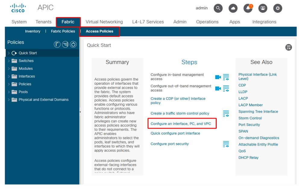
The above image shows the Quick Start page where multiple wizards can be found.
Once an access policy is defined, the generic recommendation is to validate the policy by making sure all the associated objects do not show any fault.
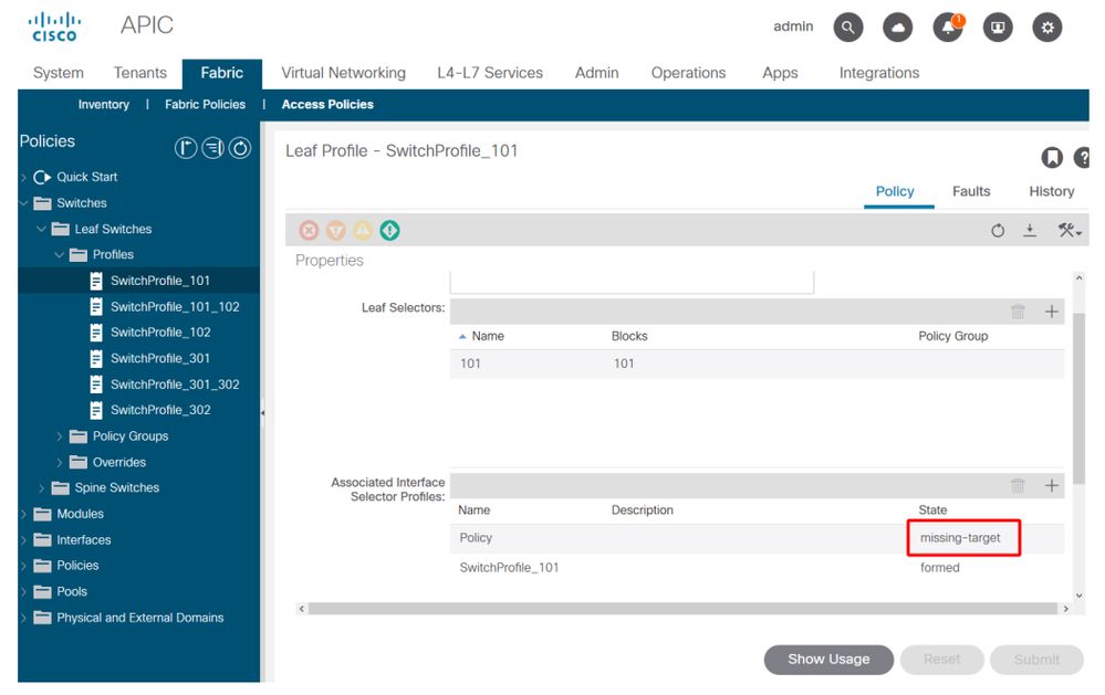
For example, in the figure below, a Switch Profile has assigned an Interface Selector Policy that does not exist. An attentive user will easily be able to spot the 'missing-target' state of the object and verify that a fault was flagged from the GUI:
Leaf Profile — SwitchProfile_101
Leaf Profile — SwitchProfile_101 — Fault
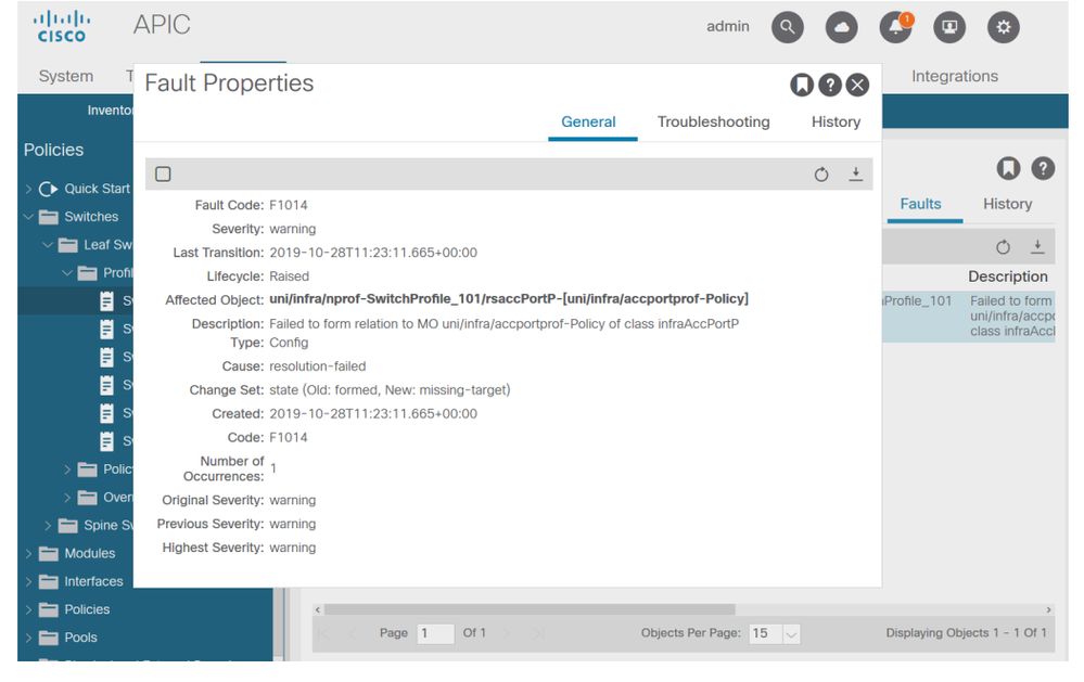
In this case, correcting the fault would be as easy as creating a new Interface Selector Profile called 'Policy'.
The manual configuration of basic access policies will be explored in the following paragraphs.
Access policies manual basic configurations
When deploying access policies, objects are being defined to express the intended use of the given downlinks. The declaration which programs the downlinks (e.g. EPG Static Port assignment) relies on this expressed intent. This helps to scale the configuration and logically group similar use objects, such as switches or ports specifically connected to a given external device.
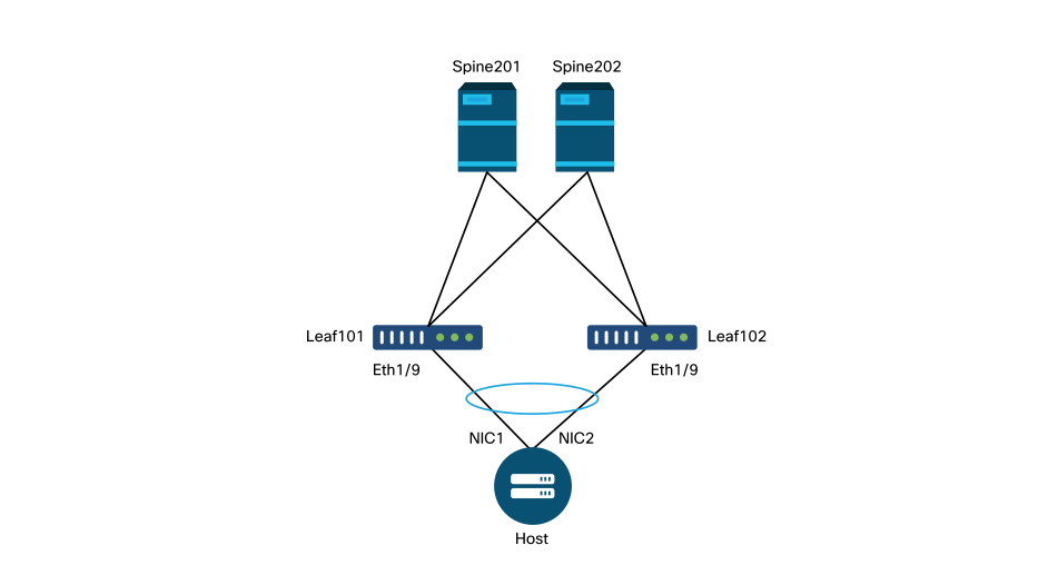
Reference the topology below for the remainder of this chapter.
Topology of access policy definition for dual-homed server
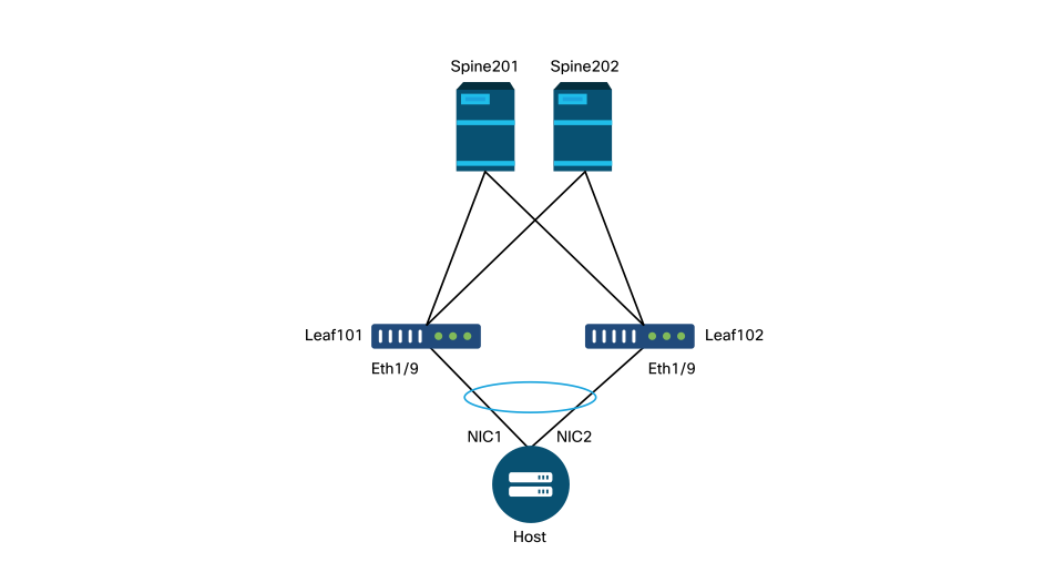
A web server is connected to an ACI fabric. The web server has 2 Network Interface Cards (NICs) which are configured in an LACP port-channel. The web server is connected to port 1/9 of leaf switches 101 and 102. The web server relies on VLAN-1501 and should reside in the EPG 'EPG-Web'.
Configure the Switch Policy
The first logical step is to define which leaf switches will be used. The 'Switch Profile' will contain 'Switch Selectors' which define the leaf node IDs to be used.
Switch policies
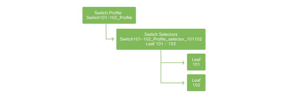
The general recommendation is to configure 1 Switch Profile per individual leaf switch and 1 Switch Profile per VPC domain pair, using a naming scheme which indicates the nodes which are part of the profile.
The Quick Start deploys a logical naming scheme which makes it easy to understand where it is applied. The completed name follows the 'Switch<node-id>_Profile' format. As an example, 'Switch101_Profile' will be for a switch profile containing leaf node 101 and Switch101-102_Profile for a Switch Profile containing leaf nodes 101 and 102 which should be part of a VPC domain.
Configure the Interface Policy
Once the switch access policies have been created, defining the interfaces would be the next logical step. This is done by creating an 'Interface Profile' which consists of 1 or more 'Access Port Selectors' which contain the 'Port Block' definitions.
Interface policies

To form the relationship between the 'Interface Profile' and the switches involved, link the 'Switch Profile' to the 'Interface Profile'.
'Interface Profiles' can be defined in many ways. Similar to 'Switch Profiles', a single 'Interface Profile' can be created per physical switch along with an 'Interface Profile' per VPC domain. These policies should then have a 1-to-1 mapping to their corresponding switch profile. Following this logic, the fabric access policies are greatly simplified which makes it easy for other users to understand.
The default naming schemes employed by the Quick Start can also be used here. It follows the '<switch profile name>_ifselector' format to indicate this profile is used to select interfaces. An example would be 'Switch101_Profile_ifselector'. This example 'Interface Profile' would be used to configure non VPC interfaces on leaf switch 101 and it would only be associated to the 'Switch101_Profile' access policy.
Switch Profile associated to Interface Profile
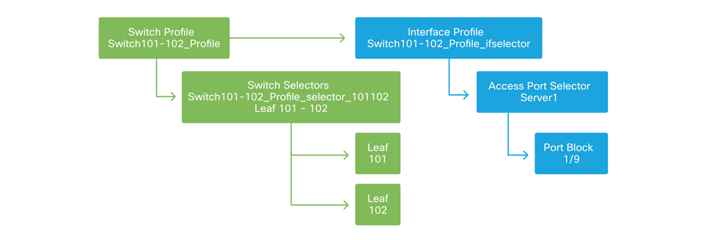
Notice that since an 'Interface Profile' with Eth 1/9 is connected to a 'Switch Profile' which includes both leaf switch 101 and 102, provisioning Eth1/9 on both nodes begins simultaneously.
At this point, leaf switches and their ports have been defined. The next logical step would be to define characteristics of these ports. The 'Interface Policy Group' allows for the definition of these port properties. A 'VPC Interface Policy Group' will be created to allow for the above LACP Port-Channel.
Policy Group

The 'VPC Interface Policy Group' gets associated to the 'Interface Policy Group' from the 'Access Port Selector' to form the relationship from leaf switch/Interface to port properties.
Switch and Interface Profiles combined
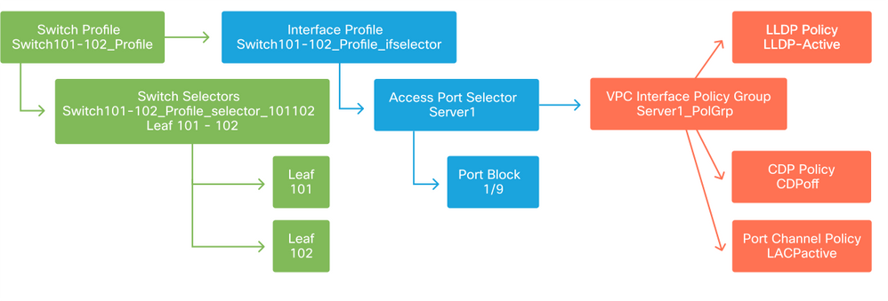
Configure the VPC
To create the LACP port-channel over 2 leaf switches, a VPC domain must be defined between leaf switch 101 and 102. This is done by defining a 'VPC Protection Group' between the two leaf switches.
VPC

Configure VLAN pools
The next logical step will be to create the VLANs that will be used on this port, in this case VLAN-1501. The definition of a 'VLAN Pool' with 'Encap Blocks' completes this configuration.
When considering the size of VLAN pool ranges, keep in mind that most deployments only need a single VLAN pool and one additional pool if using VMM integration. To bring VLANs from a legacy network into ACI, define the range of legacy VLANs as a static VLAN pool.
As an example, assume VLANs 1-2000 are used in a legacy environment. Create one Static VLAN pool which contains VLANs 1-2000. This will allow to trunk ACI Bridge Domains and EPGs towards the legacy fabric. If deploying VMM, a second dynamic pool can be created using a range of free VLAN IDs.
VLAN Pool

Configure Domains
The next logical step is to create a 'Domain'. A 'Domain' defines the scope of a VLAN pool, i.e. where that pool will be applied. A 'Domain' could be physical, virtual, or external (bridged or routed). In this example, a 'Physical Domain' will be used to connect a bare metal server into the fabric. This 'Domain' gets associated to the 'VLAN Pool' to allow the required vlan(s).
Physical Domains

For most deployments, a single 'Physical Domain' is enough for bare metal deployments and a single 'Routed Domain' is sufficient for L3Out deployments. Both can map to the same 'VLAN Pool'. If the fabric is deployed in a multi-tenancy fashion, or if more granular control is required to restrict which users can deploy specific EPGs & VLANs on a port, a more strategic access policy design should to be considered.
'Domains' also provide the functionality to restrict user access to policy with 'Security Domains' using Roles Based Access Control (RBAC).
When deploying VLANs on a switch, ACI will encapsulate spanning-tree BPDUs with a unique VXLAN ID which is based on the domain the VLAN came from. Due to this, it is important to use the same domain whenever connecting devices which require STP communication with other bridges.
VLAN VXLAN IDs are also used to allow VPC switches to synchronize VPC learned MAC and IP addresses. Due to this, the simplest design for VLAN pools is to use a single pool for static deployments and create a second one for dynamic deployments.
Configure the Attachable Access Entity Profile (AEP)
Two major chunks of access policy configuration have now been completed; the switch and interface definitions, and the domain/VLAN(s) definitions. An object called 'Attachable Access Entity Profile' (AEP) will serve to tie these two chunks together.
A 'policy group' is linked towards an AEP in a one-to-many relationship which allows for the AEP to group interfaces and switches together which share similar policy requirements. This means that only one AEP needs to be referenced when representing a group of interfaces on specific switches.
Attachable Access Entity Profile
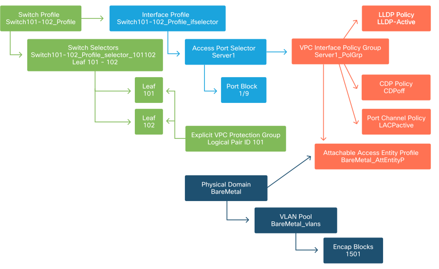
In most deployments, a single AEP should be used for static paths and one additional AEP per VMM domain.
The most important consideration is that VLANs can be deployed on interfaces through the AEP. This can be done by mapping EPGs to an AEP directly or by configuring a VMM domain for Pre-provision. Both these configurations make the associated interface a trunk port (‘switchport mode trunk' on legacy switches).
Due to this, it is important to create a separate AEP for L3Out when using routed ports or routed sub-interfaces. If SVIs are used in the L3Out, it is not necessary to create an additional AEP.
Configure the tenant, APP, and EPG
ACI uses a different means of defining connectivity by using a policy-based approach.
The lowest level object is called an 'Endpoint Group' (EPG). The EPG construct is used to define a group of VMs or servers (endpoints) with similar policy requirements. 'Application Profiles', which exist under a tenant, are used to logically group EPGs together.
Tenant, APP, and EPG

The next logical step is to link the EPG to the domain. This creates the link between the logical object representing our workload, the EPG, and the physical switches/interfaces, the access policies.
EPG to Domain link
Configure the EPG Static Bindings
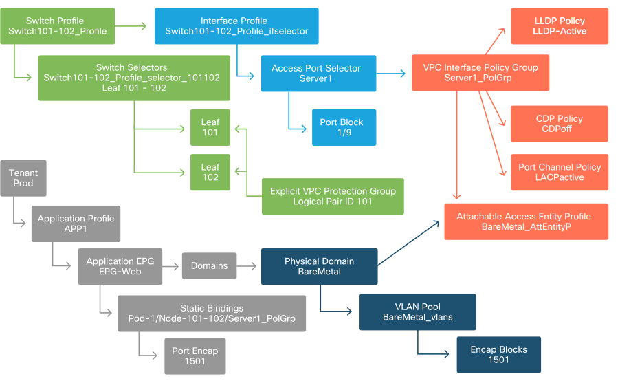
The last logical step is to program the VLAN onto a switch interface for a given EPG. This is especially important if using a physical domain, as this type of domain requires an explicit declaration to do so. This will allow the EPG to be extended out of the fabric and it will allow the bare metal server to get classified into the EPG.
Static Bindings

The referenced 'Port Encap' needs to be resolvable against the 'VLAN Pool'. If it is not, a fault will be flagged. This is discussed in the "Troubleshooting workflow" section of this chapter.
Summary of the access policy configuration
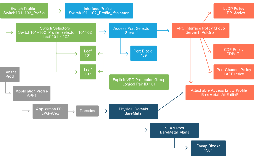
The following diagram summarizes all the objects created to allow connectivity for the host through VLAN-1501, using a VPC connection to leaf switch 101 and 102.
Bare-metal ACI connectivity
Connecting additional servers
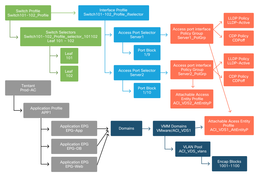
With all the previous policies created, what would it mean to connect one more server on port Eth1/10 on leaf switches 101 and 102 with a port-channel?
Referring to the 'Bare-metal ACI connectivity' diagram, the minimum following will need to be created:
- An extra Access Port Selector and Port Block.
- An extra VPC Interface Policy Group.
- An extra Static Binding with Port Encap.
Note that for LACP port-channels, a dedicated VPC Interface Policy Group must be used as this VPC Policy Group is what defines the VPC id.
In the case of individual links, the non-VPC Interface Policy Group could be re-used for the extra server if the link requires the same port properties.
The resulting policies would look like the following image.
Connecting server2 into the setup
What is next?
The next section will go through a few access policy failure scenarios, starting with the topology and use case discussed in this overview.
Troubleshooting workflow
The following troubleshooting scenarios could be encountered when working with access policies:
- A missing relationship between two or more entities in the access policy, such as access policy group not linked to an AEP.
- A missing or unexpected policy is tied to a given access policy, such as an LLDP policy named 'lldp_enabled', while in reality the policy configuration has LLDP rx/tx disabled.
- A missing or unexpected value in the access policy, such as the configured VLAN ID encap missing from the configured VLAN Pool.
- A missing relationship between the EPG and access policy, such as no physical or virtual domain association to the EPG.
Most of the above troubleshooting involves walking through the access policy relationships to understand if any relationships are missing, or to understand which policies are configured and/or whether the configuration is resulting in the desired behavior.
Using the "Configure interface, PC, and VPC Quick Start" for Troubleshooting
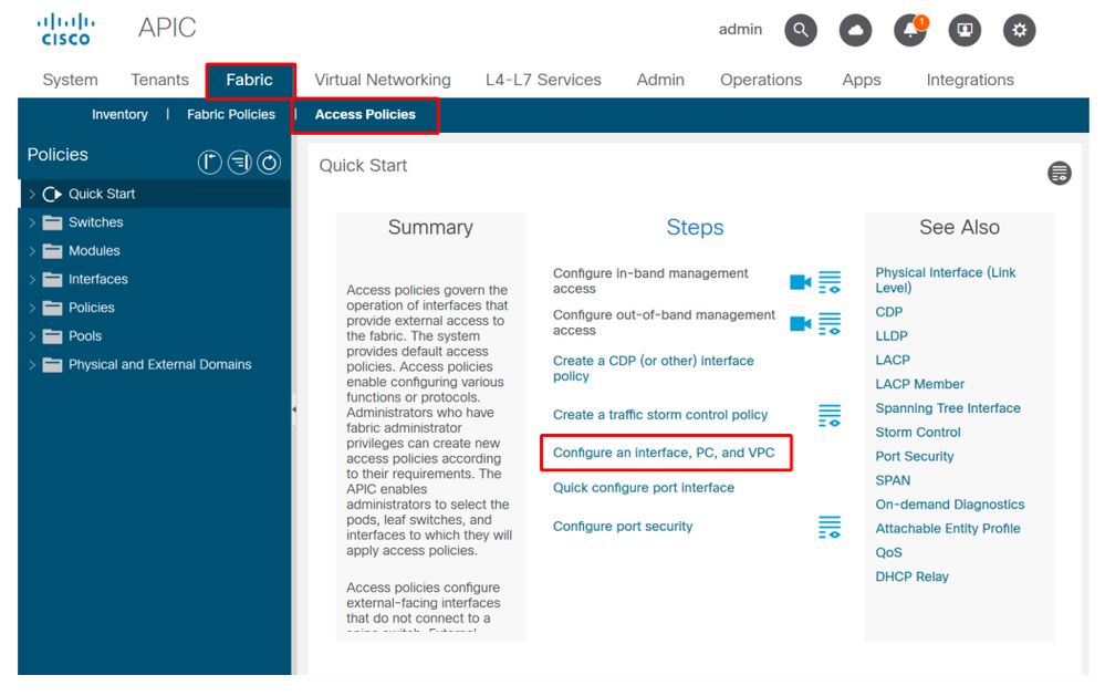
Within the APIC GUI, the 'Configure Interface, PC, and VPC' quick start wizard facilitates access policy lookup by providing the administrator an aggregated view of existing access policies. This quick start wizard can be found in the GUI at:
'Fabric > Access Policies > Quick Start > Steps > Configure Interface, PC, and VPC'.
Location of 'Configure Interface, PC, and VPC' Quick Start
Even though the wizard has 'Configure' in the name, it is exceptionally handy for providing an aggregated view of the many access policies that must be configured to get interfaces programmed. This aggregation serves as a single view to understand which policies are already defined and effectively reduces the number of clicks required to begin isolating access policy-related issues.
When the Quick Start view is loaded, the 'Configured Switch Interfaces' view (top-left pane) can be referenced to determine existing access policies. The wizard groups the entries underneath folders that represent either individual or multiple leaf switches, depending on the access policies configuration.
As a demonstration of the wizard's value, the following wizard screenshots are presented, knowing the reader has no previous understanding of the fabric topology:
Demo view of 'Configure Interface, PC, and VPC' Quick Start
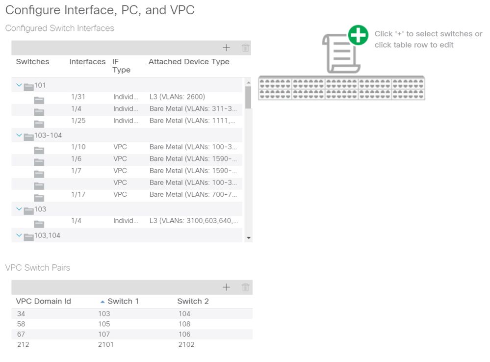
The 'Configured Switch Interfaces' pane shows access policy mappings. The 'VPC Switch Pairs' pane shows completed VPC Protection Group definitions.
The table below shows a subset of completed access policy definitions that can be derived from the above screenshot.
Subset of completed access policies that can be derived from the above Quick Start view
|
Switch Node |
Interface |
Policy Group Type |
Domain Type |
VLANs |
|
101 |
1/31 |
Individual |
Routed (L3) |
2600 |
|
101 |
1/4 |
Individual |
Phys (Bare Metal) |
311-3..? |
|
103-104 |
1/10 |
VPC |
Phys (Bare Metal) |
100-3..? |
The VLAN column entries are intentionally incomplete given the default view.
Similarly, the completed 'VPC Protection Group' policies can be derived from the 'VPC Switch Pairs' view (bottom-left pane). Without 'VPC Protection Groups', VPCs cannot be deployed as this is the policy which defines the VPC Domain between two leaf nodes.
Take into consideration that due to pane sizing, long entries are not completely visible. To view the full value of any entry, hover the mouse pointer on the field of interest.
Mouse pointer is hovering over 'Attached Device Type' field for 103-104, int 1/10 VPC entry:
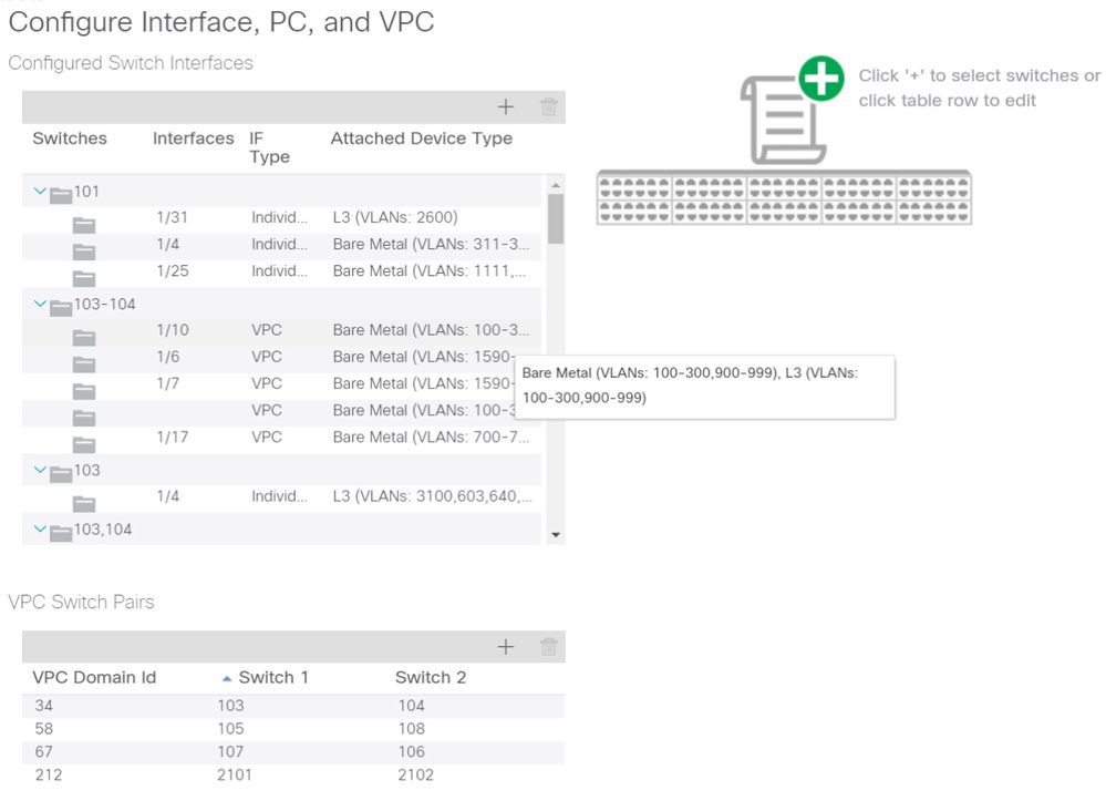
By hovering the mouse over the pane, the complete entries are visible.
Updated subset of completed access policies using mouse-over details
|
Switch Node |
Interface |
Policy Group Type |
Domain Type |
VLANs |
|
101 |
1/31 |
Individual |
Routed (L3) |
2600 |
|
101 |
1/4 |
Individual |
Phys (Bare Metal) |
311-320 |
|
103-104 |
1/10 |
VPC |
Phys (Bare Metal) |
100-300,900-999 |
|
103-104 |
1/10 |
VPC |
Routed (L3) |
100-300,900-999 |
Full VLAN associations can now be observed and understood for troubleshooting and verification.
Troubleshooting scenarios
For the following troubleshooting scenarios, reference the same topology from the previous chapter.
Topology from access policy 'Introduction' section
Scenario 1: Fault F0467 — invalid-path, nwissues
This fault is raised when a switch/port/VLAN declaration is made without the corresponding access policies in place to allow that configuration to be applied properly. Depending on the description of this fault, a different element of the access policy relationship may be missing.
After deploying a static binding for the above VPC interface with trunked encap VLAN 1501 without the corresponding access policy relationship in place, the following fault is raised on the EPG:
Fault: F0467
Description: Fault delegate: Configuration failed for uni/tn-Prod1/ap-App1/epg-EPG-Web node 101 101_102_eth1_9 due to Invalid Path Configuration, Invalid VLAN Configuration, debug message: invalid-vlan: vlan-1501 :STP Segment Id not present for Encap. Either the EPG is not associated with a domain or the domain does not have this vlan assigned to it;invalid-path: vlan-1501 :There is no domain, associated with both EPG and Port, that has required VLAN;
From the above fault description, there are some clear indications as to what could be causing the fault to be triggered. There is a warning to check the access policy relationships, as well as to check the domain association to the EPG.
Reviewing the Quick Start view in the scenario described above, clearly the access policy is missing VLANs.
Quick Start view where 101-102, Int 1/9 VPC is missing VLANs
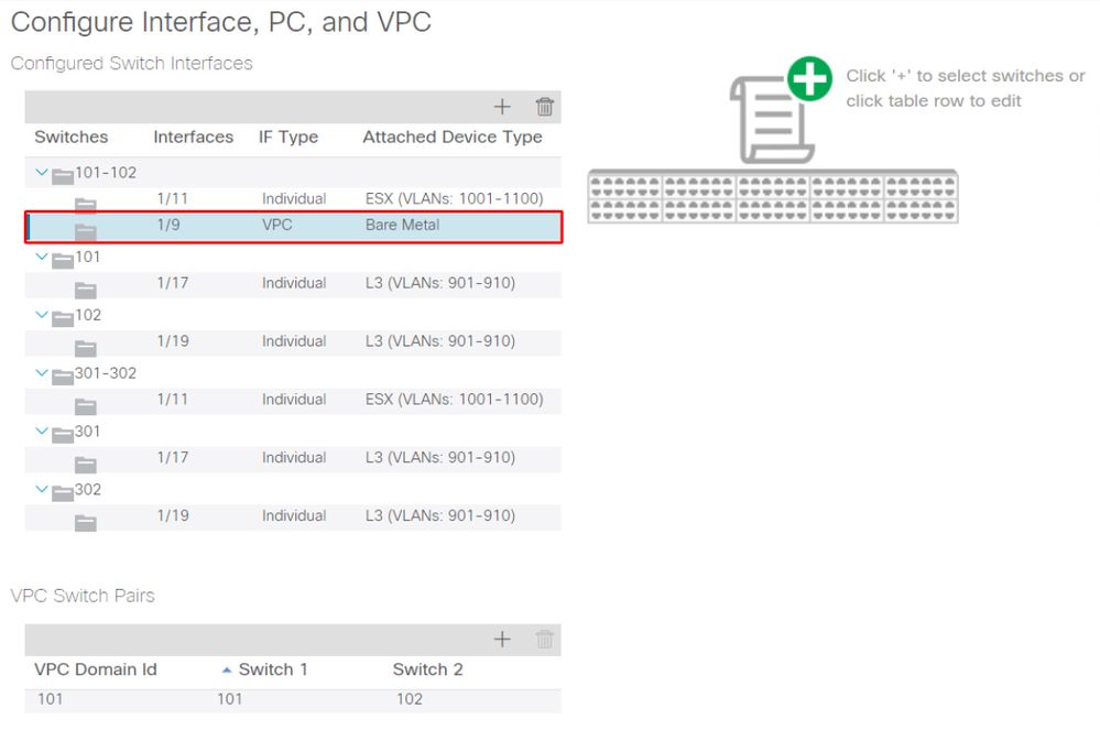
Note that the entry is missing a reference to any VLAN IDs.
Once corrected, the Quick Start view will show '(VLANs 1500-1510)'.
101-102, Int 1/9 VPC now shows Bare Metal (VLANs: 1500-1510)
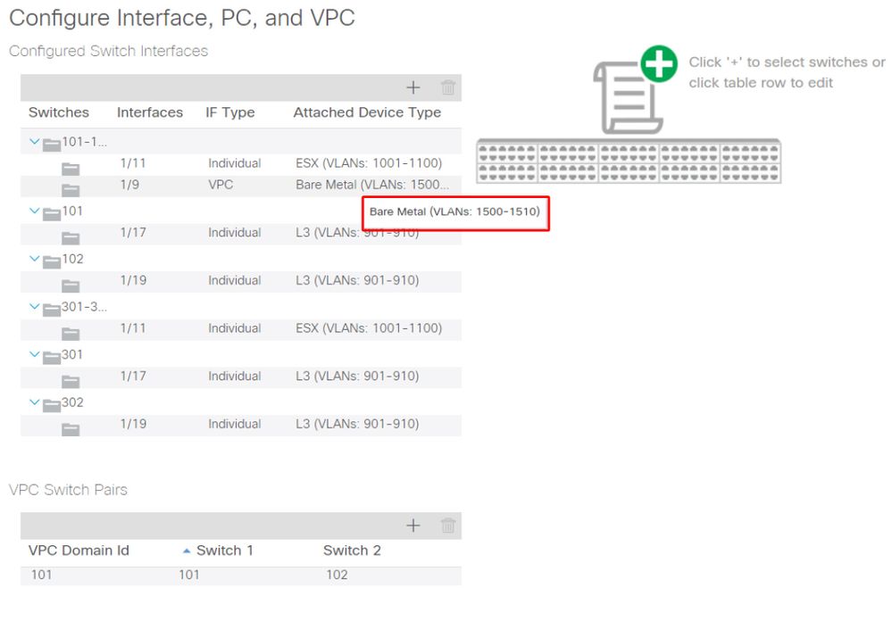
However, the EPG fault still exists with the following updated description for fault F0467:
Fault: F0467
Description: Fault delegate: Configuration failed for uni/tn-Prod1/ap-App1/epg-EPG-Web node 101 101_102_eth1_9 due to Invalid Path Configuration, debug message: invalid-path: vlan-150 : There is no domain, associated with both EPG and Port, that has required VLAN.
With the above updated fault, check the EPG domain associations to find that there are no domains tied to the EPG.
EPG-Web has Static Ports association, but is missing domain associations
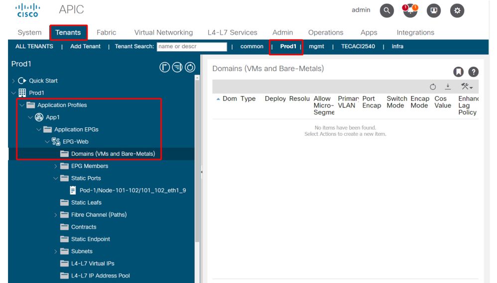
Once the domain that contains VLAN 1501 is associated to the EPG, no further faults are raised.
Scenario 2: Unable to select VPC as a path to deploy on EPG Static Port or L3Out Logical Interface Profile (SVI)
While attempting to configure a VPC as a path on an EPG Static Port or L3Out Logical Interface Profile SVI entry, the specific VPC to be deployed is not displayed as an available option.
When attempting to deploy a VPC static binding, there are two hard requirements:
- The VPC Explicit Protection Group must be defined for the pair of leaf switches in question.
- The full access policy mapping must be defined.
Both requirements can be checked from the Quick Start view as shown above. If neither is complete, the VPC will simply not show up as an available option for Static Port Bindings.
Scenario 3: Fault F0467 — fabric encap already used in another EPG
By default, VLANs have a global scope. This means that a given VLAN ID can only be used for a single EPG on a given leaf switch. Any attempt to re-use the same VLAN on multiple EPGs within a given leaf switch will result in the following fault:
Fault: F0467
Description: Fault delegate: Configuration failed for uni/tn-Prod1/ap-App1/epg-EPG-BusinessApp node 102 101_102_eth1_8 due to Encap Already Used in Another EPG, debug message: encap-already-in-use: Encap is already in use by Prod1:App1:EPG-Web;
Aside from selecting a different VLAN, another option to make this configuration work is to consider the usage of 'Port Local' VLAN Scope. This scope allows for VLANs to be mapped on a per-interface basis which means that VLAN-1501 could potentially be used for different EPGs, across multiple interfaces, on the same leaf.
Although 'Port Local' scope gets associated on a Policy Group basis (specifically via an L2 policy), it is applied at the leaf level.
Location to change 'VLAN Scope' setting within APIC GUI
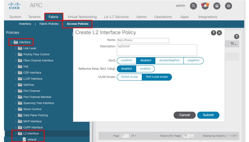
Before implementing the 'Port Local' VLAN scope configuration, review the "Cisco APIC Layer 2 Networking Configuration Guide" on Cisco.com to ensure that its limitations and design restrictions are acceptable for the desired use cases and designs.
Special mentions
Show Usage
While not specific to access policies, a button is available on most objects in the GUI that is labeled 'Show Usage'. This button performs a policy lookup rooted at the selected object to determine which leaf nodes/interfaces have a direct relationship to it. This can be useful for both the general lookup scenario as well as to gain an understanding of whether a specific object or policy is even in use.
In the screenshot below, the selected AEP is being used by two different interfaces. This implies that making a modification to the AEP will have a direct impact on the associated interfaces.
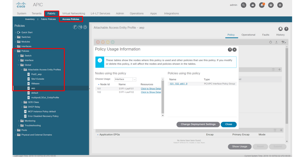
Overlapping VLAN Pools
While the function of access policies is to allow a specific VLAN to be deployed onto an interface, there is additional usage that must be considered during the design phase. Specifically, the domain gets used in the calculation of the VXLAN ID (called Fabric Encap) tied to the external encapsulation. While this functionality generally has no major bearing on dataplane traffic, such IDs are especially relevant for a subset of protocols which flood through the fabric, including Spanning Tree BPDUs. If VLAN-<id> BPDUs ingressing on leaf1 are expected to egress Leaf 2 (e.g. having legacy switches converging spanning-tree through ACI), VLAN-<id> must have the same fabric encap on both leaf nodes. If the fabric encap value differs for the same access VLANS, the BPDUs will not traverse the fabric.
As mentioned in the previous section, avoid configuration of same VLANs in multiple domains (VMM vs Physical, for example) unless special care is being taken to ensure that each domain is only ever applied to a unique set of leaf switches. The moment both domains can be resolved onto the same leaf switch for a given VLAN, there is a chance that underlying VXLAN can be changed after an upgrade (or clean reload) which can lead for example to STP convergence issues. The behavior is a result of each domain having a unique numerical value (the 'base' attribute) which is used in the following equation to determine VXLAN ID:
VXLAN VNID = Base + (encap — from_encap)
To validate which domains are pushed onto a given leaf, a moquery can be run against the 'stpAllocEncapBlkDef' class:
leaf# moquery -c stpAllocEncapBlkDef

# stp.AllocEncapBlkDef
encapBlk     : uni/infra/vlanns-[physvlans]-dynamic/from-[vlan-1500]-to-[vlan-1510]
base         : 8492
dn           : allocencap-[uni/infra]/encapnsdef-[uni/infra/vlanns-[physvlans]-dynamic]/allocencapblkdef-[uni/infra/vlanns-[physvlans]-dynamic/from-[vlan-1500]-to-[vlan-1510]]
from         : vlan-1500
to           : vlan-1510
From this output, discern the following access policy definitions:
- There is a programmed VLAN pool with a block of VLANs explicitly defining VLANS 1500-1510.
- This block of VLANs is tied to a domain named 'physvlans'.
- The base value used in VXLAN calculation is 8492.
- The resulting VXLAN calculation for VLAN-1501 would be 8492 + (1501-1500) = 8493 as the fabric encapsulation.
The resulting VXLAN ID (in this example, 8493) can be verified with the following command:
leaf# show system internal epm vlan all
+----------+---------+-----------------+----------+------+----------+-----------
  VLAN ID    Type      Access Encap     Fabric    H/W id  BD VLAN    Endpoint
                       (Type Value)     Encap                          Count
+----------+---------+-----------------+----------+------+----------+-----------
13          Tenant BD NONE            0 16121790   18     13         0
14            FD vlan 802.1Q       1501 8493       19     13         0
If there is any other VLAN pool containing VLAN-1501 that gets pushed onto the same leaf, an upgrade or clean reload could potentially grab unique base value (and subsequently a different Fabric Encap) which will cause BPDUs to stop making it to another leaf which is expected to receive BPDUs on VLAN-1501.
Revision History
| Revision | Publish Date | Comments |
|---|---|---|
1.0 |
05-Aug-2022 |
Initial Release |
Contributed by Cisco Engineers
- ACI Escalation Engineers
- Technical Marketing
Contact Cisco
- Open a Support Case

- (Requires a Cisco Service Contract)
 Feedback